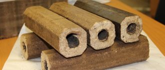
Production is unthinkable without pressing operations, and modern production even more so: the processing of metals and materials in general by cutting produces waste, which ultimately has a significant impact on the environment and economy. In a home workshop, in a garage, it is also difficult for an individual entrepreneur working in metal to do without stamping, forging, straightening, bending, molding (flattening), pressing and pressing out blanks and parts, but the choice of presses for individual use is not wide, but the prices are scary. A press is no less necessary just on the farm - for squeezing juice, oil, baling hay. Virgin juice/oil can only be obtained from a special press (see below); You need to press the grapes into the wine especially carefully and with skill. And with the choice of ready-made presses and their prices, the situation is similar to the previous one. Finally, rising energy prices are forcing many homeowners to think about switching their autonomous heating to waste (alternative) fuel, or at least how to make fuel pellets or briquettes from existing household waste (straw, husks, husks, sawdust, shavings); This also requires a special press. This publication is devoted to how to make a press with your own hands for these and some other purposes (also see below).
Homemade presses for various purposes
When to buy
Tabletop manual mechanical mini press
But when you under no circumstances need to make a press yourself, it is when you are engaged in precision mechanics, optics, or jewelry work. All homemade presses are not particularly accurate: you can’t make them better at home and/or homemade conditions. And an inaccurate mini-press can break or irreparably damage a tiny irreplaceable part, crack a lens, a gemstone, etc. In these cases, it is still better to purchase a desktop mini-press; Of these, manual mechanical rack and pinion (see figure on the right) are widely available and their prices are reasonable.
Hit or crush?
Pressing operations are carried out mainly by pressure and impact. Impact pressing is very economical: the impact creates a wave of elasticity in the metal of the workpiece, which makes the metal flow better and resist deformation less. In the practice of amateurs and individual craftsmen, impact pressing is widely used for cold forging of metals, especially artistic ones. Impact presses are most often performed using impact-inertial ones: energy is accumulated in a mechanical storage device (flywheel, falling weight). Then the drive is brought into engagement with the press punch, which hits the workpiece. Impact-inertial presses are very compact: such a press weighs 1 ton and has dimensions of approx. 1x1 m is capable of creating an instantaneous force of more than 1000 tf. But impact pressing is one of the most accident-prone and traumatic operations, so only one option for an impact press will be considered below, suitable for use in a home workshop.
What is a compact tabletop press used for?
Tabletop presses, which are offered today by many mechanical equipment manufacturers, are divided into manual and electrically powered. The high popularity of such equipment is primarily due to its compact size, due to which it does not require a large area to place this device and operate it. The working elements of modern models of tabletop presses are made mainly of high-strength steel, which ensures a long service life of this equipment.
Mechanical manual rack press for home workshop
Tabletop mechanical presses, which are driven by applying physical force, are very popular among owners of small workshops and home craftsmen. This popularity is explained by the simplicity of the design of mechanical hand presses, their unpretentiousness in operation and maintenance, which even a novice home craftsman can cope with. In addition, these desktop devices do not require any consumables to operate.
The most common technological operations that are successfully performed using a manual tabletop press are:
- pressing out and pressing of various bushings and elements of bearing units;
- cutting small parts;
- stamping;
- creating connections using the riveting method.
A manual screw-type press for work related to crimping bindings, books or covers, can also be used in carpentry when gluing workpieces
Tabletop mechanical presses are quite versatile devices that can be used to process products made from various materials, such as:
- metals and their alloys;
- polymers and plastics;
- leather;
- wood;
- cardboard;
- rubber.
Another important advantage that desktop mechanical presses have is that such equipment can operate effectively even at sub-zero temperatures.
Hand press for punching holes in leather
Which one should I do?
Pressure pressing allows you to perform almost all pressing operations necessary in everyday life. Homemade presses are most often made energy-autonomous, i.e. without a separate drive, working fluid reservoirs, pumping stations, etc. The choice of one or another design of the press is ultimately determined by its purpose and working force.
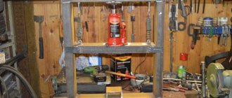
It is easiest to use a car jack as a power unit built into the press - it develops a force of up to 100 tf, and jacks for 10 tf are commonly used. The only operation that a jack press cannot handle is molding (flattening) the ends of rods during artistic cold forging.
The most commonly used jack is a hydraulic bottle jack (but see also below). In this case, a hydraulic press can be made according to one of the traces. frame design diagrams (see figure):
Basic design diagrams of homemade presses
- Pos. A – the jack is turned upside down, tightly fixed to the fixed upper cross-beam, and a punch is attached to the head of the working rod of the jack. This is the simplest and at the same time reliable and vibration-resistant design (see below for the role of vibrations in the operation of the press). Disadvantages - if the jack is needed for its intended purpose, dismantling it is quite difficult and time consuming, and swinging the lever of a jack hanging upside down is not very handy.
- Pos. B – diagram with a movable table. Structurally more difficult, because a movable traverse is added - a table. They pump the jack as always, it’s easy to remove it, because... it may not be secured at all. Disadvantages – worst vibration resistance; in addition, the technology of most pressing operations is designed for the punch to press on the workpiece or part from above, but if it’s the other way around, it’s difficult and may not work out at all. But for repair and/or mechanical assembly work, this is the best option: if you need to squeeze out a tightly rusted shaft from a pulley or bearing or, conversely, press them onto the shaft, then its (the shaft’s) length is limited only by the height of the ceiling in the workshop. In general, a hydraulic press with a moving table made from a jack is the best option for a garage or service station.
- Pos. B – with a power unit on a movable cross-beam. Structurally the most complex, but vibration-resistant, strong and durable, because the load on the weakest link - the movable traverse - is not point-based, but actually dispersed. The jack may also not be secured, but if it turns out and crashes, the consequences will be worse than if it falls off the base plate. The disadvantage is that pumping a jack that slowly creeps down is not very convenient.
Note: the base plate is a heavy, bulky, material-intensive thing. Placing a press on a slab in a workshop or garage is not always possible. Therefore, the frame of homemade presses is most often placed not on a slab, but on a lower fixed cross-beam, structurally similar to the upper one (see below). This reduces the vibration resistance of the press by approx. twice, but for amateur conditions this is acceptable.
A manually driven screw press (pos. D) allows you to create a force of up to a maximum of 1.5-2.5 tf. In working with metal it is used when this is sufficient, in the following. cases (see also video):
When pressing force less than the specified values is sufficient:
Video: manual screw press for the workshop
Large stroke required:
Video: screw press 2/2
As a small or mini press for small, not very important jobs:
Video: small screw press
How to remove:
Video: homemade press for removing bearings and pulleys
Note: a structurally simple frameless lever hand press, pos. D in Fig. But it finds greater use in everyday life and households (see below), because with its help you can develop a force of no more than 300-400 kgf.
Is it just hydraulics?
A homemade jack press can be not only hydraulic. Many passenger cars are equipped with a diamond-shaped screw jack when sold. It produces a force of no more than 2-2.5 tf, but is cheap (“a new, good one” can be purchased for 1,300 rubles). A small amount of effort is not only a drawback: the frame of a press with a screw jack can be made of a wooden beam from 150x150, and it is also possible to adapt an electric drill to it as a drive, see fig.:
Homemade mechanical press with electric drive from a screw diamond jack
If the maximum you need is to bend rods up to 8-10 mm, such a press will be enough for that. And an interesting fact: about 10 years ago, the author of the article happened to accidentally meet a figure who, working 3-4 hours on the first 2-3 days of the week, earned 20-25 thousand rubles. per month At that time the amount was considerable. How? I bought empty metal cans for half the purchase price of scrap metal, flattened them and sold them at a normal price. Most of the cans they brought were beer ones, they are aluminum, and they are expensive. He complained, however, that the work was dirty - the bulk of the raw materials were brought in by homeless people.
Pressing and vibration
Vibrations of metal stretching during pressing are the scourge of large industry, and giant presses, like the one that NKMZ supplied to the French Forzhal from the USSR, are therefore extremely complex units. But individual entrepreneurs and amateurs should also pay the most serious attention to the vibration resistance of the press. A scuff on a hardened shaft or journal of an axle shaft is an irreparable defect.
Comparative analysis of two lever presses
More than a year has passed since the moment when one of the leather sites shared with me a link to a video with a hand press, very similar to my press. According to the rules, links to third-party resources are not allowed, but finding this press is not difficult - you just need to type the phrase in the search bar of any search engine: Linear hole punching machine for leather.
The author of this press is Viktor Tataryn, a man with varied interests and skillful hands. The press was made with great love and quite neatly, the author is deservedly proud of it. But in my experienced opinion, and I have sufficient grounds for this, this product is characterized by a number of “childhood diseases” and significant design flaws. Many people don’t notice them, but they are mistakes that catch my eye, because I tried to avoid them in the design of my press. And I think a lot has been achieved in this matter. However, for comparison, you need to watch my video. To search for it, you should type in the same line the phrase: Press for working with leather.
For ease of comparison, they should probably be numbered. Let the first press performed by Viktor Tataryn be numbered No. 1, but let’s call my press number No. 2.
I first saw the video with press No. 1 on November 26, 2016, today for some reason it seems to me somewhat cut down, there are no words in it that work on the press will continue and the result will be made public. It’s strange, but the author’s playlist on YouTube has also shrunk significantly, several times over, and today there are no very interesting videos in it.
A significant difference in the designs is the location of the axis of rotation, but the devil, as we know, is in the details. It is the upper location of the rotation axis that causes fatal problems that interfere with the normal operation of the press. This is what I will try to show using the simplest graphical constructions and mathematical calculations within the school curriculum. Nothing abstruse or unusual is assumed in my reasoning, but a simple and unfounded statement, without figures and numbers in hand, in my opinion, is unconvincing and unproven.
The peculiarity of the proposed analysis is that I do not know the main dimensions of press No. 1, I do not have the opportunity to look at its drawings published in the magazine “Leatherwork” No. 2 for 2015. Therefore, the calculations will be slightly approximate, since I will try to determine its dimensions using the methods available to me directly on the monitor screen.
Judging by the design, Viktor Tataryn and I used the same profile pipes for our presses: 20x20, 20x40, 15x30. So I’ll try to use a size of 40 mm as a starting point, corresponding to the width of the pipe from which the press body is made. In photo Fig. 1 this size is 55 pixels. I'll take this ratio 55px = 40mm. for the calculation base and on this basis I will try to determine all the other main dimensions.
Fig.1
I'll start with press No. 1, it is its features that are most noticeable to me.
- The main disadvantage of this press is the upper location of the axis of rotation. In this case, the penetration of the punch into the product does not occur vertically, but at a significant angle. In this case, the force used for piercing is somewhat reduced, but what’s even worse is that a shearing force appears, and a significant one at that. This is clearly visible with every working movement of the press - the stop is constantly pushed to the side and does not perform its functions. It turns out that for each next working stroke the stop must be returned to its original position, which is extremely inconvenient. This was also noted in the commentary to the video, but the author tried not to pay attention to it. How strong this shear force is is not so difficult to determine.
In Fig. 2 there is a screenshot of this press with the markings necessary for the calculations.
Fig.2
The following notations are used here:
— BC – height of the axis of rotation above the surface of the skin;
— AC – horizontal distance from the axis of rotation to the site of skin piercing;
— AB = R – radius of the circle (trajectory of movement of the punch teeth).
Using “Pythagorean pants” we determine the value AB = R:
(But now significant difficulties have arisen when writing formulas - it is simply impossible to present them here, even such a simple one as extracting the square root. Posting them in the form of photographs sized 450x600 pixels is simply not reasonable; such a line will take up exactly as much space as photo presented just above. You’ll have to take my word for it - I won’t deceive you).
Where:
AB = 205 mm
Recalling the theorem on the similarity of triangles in geometry, and the parallelogram of force decomposition in physics, we can determine the approximate magnitude of the forces on the edge of the cutting tool.
Where does the magnitude of the vertical force come from:
Rvert. = 0.8 Рsum.
That is, only 80% of the total effort exerted by the master is used for useful work.
Now the horizontal force that moves the skin is:
Rgoriz. = 0.59 Рsum.
That is, the force that moves the skin during piercing approaches 60% of the total force, or 73% of the force used directly for piercing. This is a lot and it is unlikely to be compensated for. Even if the stop turns out to be motionless, in this case the leather part will be wrinkled.
Now let’s try to calculate the approximate (conventional for comparing two presses) forces on the handle required to punch identical holes/seams.
Let us assume that the force at the tip of the working tool should be 10 kGs. (I’ll count the old fashioned way; I don’t want to calculate in newtons)
It will look something like this, where P is the required force on the handle applied by the master:
P = (Rsum.)/K = (Rvert.)/0.8K
but first you need to determine the lever gain. It is defined simply:
K =L/R
The extension cord that flashed during the show is approximately 400mm long.
This is how the length of the lever without the extension was determined:
Thus, the total but effective length of the lever will be slightly less, approximately 800 mm. Means
K = 800/200 = 4
Therefore, the force on the lever on the part of the master is:
P =10/(0.8x4) = 3.125 kG.
In this case, the horizontal shear force will be:
Rgoriz. = 0.73Rvert. = 0.73 x 10 = 7.3 kG.
The presence of three more holes for rearranging the lever is absolutely unnecessary. The fact is that when using any of them, the situation will only worsen, due to the worsening aspect ratios in the triangle - Phoriz. (shear force) will only increase.
2. I would call the second “childhood disease” the design of the stop itself, which does not ensure its immobility during operation. There are several reasons for this, and one of them is the extremely flexible U-shaped appearance of the clamp itself with lateral fixation with a screw. Despite the use of a rather fine M6 thread in the clamping screw, this clamp simply unbends. By the way, the M6 thread is unlikely to last long; it is very easy to “break” it during prolonged work, even with your hands, and work on the press is expected to last for a long time.
3. The third problem is the lining that constantly falls and is not secured in any way. It turns out that after each working movement it needs to be corrected and put in place. It will get boring very quickly. By the way, the stop is very short and this can interfere with punching an even and straight seam, focusing only on the edge of the part.
4. Fourth – metal lever extension. It is not secured in the press, and being of sufficient length, it presents some inconvenience. It has to be almost constantly removed and installed on the press, and it is possible that it will fall on the floor and on your feet. The profile pipe from which it is made has rather sharp, not rounded, corners. I have no doubt that when working with such an extension cord, and a metal one at that, painful calluses or chafing will quickly appear on your hands, especially on women’s hands.
5. A separate conversation about the puller. Outwardly, he looks very dignified, he can cope with his job quite well. It’s just that the complexity of its production is somewhat alarming and discourages use. The first difficulty is related to the fact that in this case it is impossible to do without turning work; it is very difficult to find ready-made parts, even for one press. The second difficulty is a flat spring; finding or buying a suitable one is even more difficult. These two reasons put an end to not only the possibility of replication, but also the simple repetition of such a puller. In this case, it is also necessary to install the lugs for this spring.
6. It should be noted that the screw that clamps the working tool in the press has a very small diameter, most likely M6. Having such a large head, stripping the threads on this screw will not be difficult. It will be much worse if the thread on the screw survives, but the thread in the press body is damaged. Such a seemingly insignificant defect will cause the press to stop completely.
7. The press does not have a developed base, it is extremely unstable and prone to tipping over on its side. To prevent this from happening, it is necessary to use at least two clamps with extensions inserted into the lower part of the press. This not only significantly increases its dimensions, but also reduces its mobility and ease of use.
8. There are no soft pads on the bottom surface of the press to protect the surface of the work table from damage in the form of scratches.
9. The press does not have a work table on which parts can be placed; they will have to be constantly held by hand to prevent them from moving and falling.
Apparently, it was the combination of these reasons that did not allow the author to complete even two stitches in a row, and even on thin artificial leather. There were not even two holes made at a given distance, both from the edge and between each other. I'm not even talking about an even chain of seams or holes. Only the power capabilities of the press were demonstrated, and nothing more. All the holes were pierced anywhere and anyhow. By the way, you should also pay attention to the fact that all working movements were performed exclusively with two hands, and by a man of heavy build. Can a fragile girl do such work? The question is not as simple as it seems.
It is also worth paying attention to how the tabletop bends, even when working with thin leather. This suggests that the applied forces were significantly greater than the calculated 3 kGs.
What I liked about this press is the adjustable screw at the top, which allows you to use tools of different lengths. It’s possible that someday I’ll try to install one of these on my press.
Now I move on to press No. 2, which I made myself. Its appearance and main dimensions are shown in photos Fig. 4 and Fig. 5.
- In this case, you can get by with constructing only one triangle in Fig. 4, which is necessary to calculate the effective length of the lever. It is determined by the well-known formula (Pythagogian pants): R = 462 mm.
Figure 5 shows that the distance from the axis of rotation to the teeth of the punch is 100 mm. Thus, the lever gain will be:
K = 462/100 = 4.62
Consequently, in order to achieve a force on the teeth of the punch, taken equal to 10 kG, a force equal to:
P = 10/K = 10/4.62 = 2.16 kG.
It is not difficult to determine how many times the force on press No. 2 will be less than on press No. 1.
3,125/2,16 = 1,43
that is, almost 1.5 times less, considering that the dimensions of the lever with the extension are also noticeably smaller - 500 mm versus 850 mm for press No. 1.
In this case, it is not necessary to make geometric constructions to determine the shear force, since the axis of rotation is almost at the same level with the point of immersion of the punches into the skin. Thus, there are no horizontal forces contributing to shear or collapse of the workpiece; only the vertical component of the forces is present.
2. In this press, the guide ruler (stop) is securely fixed using a closed bracket made of a profiled steel pipe with a cross-section of 25x40 mm. Fixation occurs using an M8 wing screw, which can be easily and securely tightened, but it is very difficult to strip the threads on it by hand.
3. Using the same closed bracket, the wooden lining under the part to be pierced is securely fixed. During operation, it does not move or fall. On this lining you can attach a temporary stop for punching a seam or holes, focusing on the curved edge of the part. In the same spacer you can install an axis used for punching stitches or holes along a given circle.
4.A wooden piece made of hardwood is used as an extension: beech, oak or mahogany. The extension has very convenient dimensions for grasping with your hand, has rounded edges, is carefully sanded and coated with several layers of yacht varnish. Holding an extension cord made of wood in your hand is much more pleasant than a metal one. Its length is not long and is sufficient for comfortable work. For this reason, it is fixed in the rocker, but secured with only one self-tapping screw, which, if necessary, can be easily unscrewed with a screwdriver and removed.
5.And again a special conversation about the puller. At first glance, it looks somewhat frivolous and frivolous; it does not have the monumentality of the puller on press No. 1. But the flimsy bank rubber bands cope with their task, pressing the puller to the working tool, quite well, and their cost is disproportionately less, which has a noticeable impact on both the cost of the press and its final price. There is also a peculiarity in using these elastic bands - during their installation, you should pay attention to the uniform tension of the branches, otherwise the puller will begin to slowly slide to the side along the seam punch. This is not critical, but somewhat unpleasant. Perhaps this is the biggest disadvantage of my design, but I really, really don’t want to complicate it.
6. The working tool in the press, as well as the clamp of the guide ruler with the lining, is securely secured with an M8 wing screw, it is very difficult to break the thread on it by hand.
7.The press has a reliable, wide base that prevents it from tipping over on its side. And, nevertheless, given that the vertical force applied to the lever exceeds the dimensions of the base, the use of the F-shaped clamp included in the delivery kit is necessary. However, attaching lever or rack presses to a table is quite common and is not uncommon. The base is made of thick-sheet birch plywood, carefully sanded and coated with yacht varnish. Plywood was not chosen by chance - it turned out to be the most reliable and load-resistant material. During the development of the design, I tested various materials: plywood, chipboard, solid wood, MDF, OSB. Plywood turned out to be the best.
8. Soft pads made of felt or porous rubber are glued to the underside of the base, protecting the surfaces on which the press is installed from scratches and damage, and preventing spontaneous movement of the press during operation.
9. A work table is mounted on the base, of sufficient size and allowing the workpieces to be placed on its surface. The table is also made of thick-sheet plywood with rounded edges, tinted, carefully sanded and covered with several layers of yacht varnish.
When presenting my press in the video, I did not focus on its strength capabilities; it is capable of withstanding loads significantly exceeding those permissible for working tools. As far as possible, I wanted to show the operations it was designed to perform, to reveal its full potential. Show that working on it does not require any physical effort, that it is possible to use widely used tools that are already in the arsenal of most tanners and are used by them for manual work. It’s not worth mentioning about quiet operation. With external dimensions somewhat smaller than that of press No. 1, my press develops noticeably greater force and is devoid of the vast majority of “childhood diseases” characteristic of press No. 1. It is very commendable that its author posted his drawings for everyone to see, but not everyone who wants to can look at them, for this you need to buy a magazine. And even fewer people will be able to repeat the manufacture of a press on their own; placing orders with a turner, mechanic or welder will not seem cheap. At the same time, all the “childhood diseases” will be revealed as a whole package, where would we be without them? For this reason, Press No. 1 can only be considered as a working life-size model and nothing more.
Its main problems are the upper location of the rotation axis and the doubled size from the rotation axis to the point of contact of the tool with the product (205 mm versus 100 mm on mine), which significantly reduces the effectiveness of the lever.
Surely some readers will have a completely expected question - why don’t I post the drawings of my press here? The answer is extremely simple - it makes no sense, for many reasons. The first of them is the impossibility of purchasing all the necessary materials in one store at fairly reasonable prices, even in a city like St. Petersburg. You will have to visit a number of stores and trading centers, where, for example, profile pipes, four sizes (20x20, 15x30, 20x40 and 25x40), will be offered in lengths from three meters, plywood in whole sheets, welding electrodes and wire in packs and reels, Hammerite paint and yacht varnish in cans. These costs alone will exceed my asking price. But this is not enough - you will need a lot of other, not cheap, small things, a lot of consumables and a large set of all kinds of tools. But, even having all this wealth and lumping it into one pile... the press will not work, solid skills in mastering all these tools are required. Alas, without all this you cannot create abs. Scattering orders among several craftsmen is unlikely to turn out to be reasonable, cheap, fast and devoid of any misunderstandings.
Isn’t it better and easier, if you have the opportunity and desire, to purchase my press, devoid of these shortcomings, capable of actually performing a number of different operations, significantly facilitating the work of a leatherworker, and at a reasonable price?
Sometimes you can hear: “Buy a rack and pinion press, and you will be happy!” But this wish is no better than others, such as: - “Catch the Goldfish/Firebird/talking Pike or the Frog Princess and you will……..”. The well-wisher forgets that any rack press is “tailored” to perform purely individual tasks and expanding its capabilities is associated with significant costs for modernization, including a universal clamp for tools with various shanks, a puller when working with seam punches and notches of various types, with guides and other devices. In reality, all this is quite troublesome and sometimes impossible. For example, my track record includes several years of professional work as a turner, and today I try to avoid turning parts. The reason is simple - not only is the lathe missing, but there are no longer any familiar turners left. And there is no escape from this, alas.
Please note that working with the press requires certain skills. I am absolutely sure that potential buyers do not have such skills and cannot yet; none of them have ever had the opportunity to work on such a press. There are no electronics here that can control the press settings - you have to do everything yourself. Just don’t despair if you can’t get the desired result from the first minutes of owning this tool. Skills are developed very quickly. To do this, you need to carefully watch my video on YouTube several times. Why several? Yes, because during the first viewing, many “little things” are overlooked, which are the key to successful work. During subsequent viewings, they certainly become visible and are added to the “treasury of experience.”
I wish creative success not only to the owners of this press, but also to all visitors to this page.
Sincerely, Simply Grandfather.
Jack press: critical links
Vibrations during press operation often reveal themselves as creaking and groaning metal. Mechanical stresses in the elements of its design are inaudible and invisible, but can quickly negate the efforts and costs of its creator, and a broken crossarm can cause injury and damage. Therefore, the choice of construction materials for the press and its technical design as a whole must be taken no less seriously.
An erroneous solution would be a welded frame made of corrugated pipe (item 1 in the figure below): it practically does not dampen vibration, and welded seams are susceptible to cracking due to the forces generated during pressing. The corrugated pipe is quite massive, very elastic and therefore is a good energy accumulator. That is, if a crack creeps along one of the seams, the heavy traverse with sharp corners can instantly break off and fly to the side.
Examples of erroneous and correct technical execution of a homemade press frame
The frame of a homemade press must be made from channels, single or paired. The I-beam fits worse: at the slightest asymmetry of the pressing force relative to the vertical axis of the frame, significant transverse stresses arise in the I-beam flange, which is contraindicated for this type of profile. In addition, the I-beam is not designed to accept concentrated loads.
A frame welded from a single channel with reinforcing jibs (item 2 in the figure) will be quite reliable and stable under a load of approx. up to 5 tf; A 10 ton jack is too strong for this press. Press crossbars for a pressing force of up to 12-15 tf should be made from paired channels with the shelves facing outwards, pos. 3. This is again the best option for a garage or service station: there is no need to make holes in the traverses for the passage of shafts, which would unacceptably weaken the frame. If the press is designed to work at maximum effort (stamping, forming, bending), then the best option is a powerful single channel (see below) and a bolted frame, pos. 4; Tack welding in this case is technological, facilitating frame assembly. Bolts, firstly, will prevent sudden destruction of the frame. Secondly, they will be good vibration absorbers.
Which channel should I take?
The standard dimensions of the channel for the hydraulic press frame are selected from the jack as follows. in the following way (it is assumed that the profile is made of ordinary structural steel St44 or similar, and the traverses are solid):
- For force up to 2 tf – single from 80x40x4 mm; paired from 60x30x4 mm.
- For a force of 2-5 tf - single from 100x50x6 mm; paired from 80x40x4 mm.
- For a force of 5-10 tf - single from 160x80x8 mm; paired from 120x60x6 mm.
- For a force of 10-15 tf - single from 220x110x12 mm; paired from 150x75x8 mm.
- For force up to 25 tf – single from 280x140x15 mm; paired from 180x90x9 mm.
What are the columns made of?
Homemade hydraulic press with twin round columns
The columns of the press frame do not work for bending, like traverses, but for tension, which the metal resists much better. However, the design of the columns mainly determines the vibration resistance of the press. The channel is not ideal in this regard; it does not dampen vibrations well. To test, tap with a hammer on the sections of channel and square corrugated pipe - they ring almost the same. The sound from a solid steel rod will be much muffled. In addition, round press columns take lateral loads well, especially if the columns are paired. In this case, the press turns out to be as compact and light as possible (see figure on the right), which significantly or completely compensates for its increased labor intensity.
Note : if the press is designed for small forces (mechanical assembly and repair work), then the round columns of its frame can be made from pipes, see video:
Video: jack press
Design examples
Vibration and mechanical stability of the press are very important when repairing and maintaining cars; especially cars. Scuffing and misalignment of the fit of mating parts is not everything; the appearance of the machine is also important. That is, the press used for straightening and/or tuning a car must have the smoothest possible motion and be as accurate as possible. This is achieved by the increased material and labor intensity of the design: the columns are made of turned steel, and the table and traverses are made of solid metal plates.
Drawings of a hydraulic press from a jack with increased accuracy and stability are shown in Fig.:
Drawings of a hydraulic press (from a jack) of increased accuracy and stability
Without compromising the performance of the press, in the geometric center of its upper fixed traverse (part 1), you can drill a hole with a diameter of up to 40 mm for the passage of the shaft/axis when pressing mating parts onto it or, conversely, pressing it out of them. Maximum short-term (10 min/1.5 hour break) working force – approx. 10 ts.
On the trail. rice. Drawings of a press of a similar design and technical design, but for production and technological purposes, are given.
Drawings of a production and technological hydraulic press from a jack with a force of 12 tf
The maximum force is already regular long-term: up to 50% of the working time, therefore the design of this product is much more complicated. The special feature of this press is its double combination frame. Its chassis is on round turned columns, and its support is welded from channels. This frame dampens vibrations very well in almost any fashion. The fact is that the mechanical quality factor of a square pipe welded end-to-end from channels is very low: the elastic waves that enter it, figuratively speaking, become entangled in metal of uneven thickness and are additionally damped in the welds. For more information on the experience of amateur manufacturing of hydraulic presses from jacks, see the video:
Video: press with an inverted jack and a frame made of corrugated pipes
Video: hydraulic press with movable table
Video: press with a movable traverse
Note: just in case - in Fig. drawings of a hydraulic press frame from a jack for a force of up to 100 tf.
Press hammer
To put an end to repair and technological presses, let’s remember what we promised: how can impact pressing be used in a home workshop or at an individual entrepreneur? In the form of a pedal press hammer; It can be used as forging, riveting and stamping.
Presses of this type are also called lever hammers. Their ancestor is a forging hammer driven by a water wheel. The impact force of the press hammer is far from record-breaking, only a few thousand tons. But due to the characteristics of the behavior of metal under impact described above, lever hammers are quite effective, especially since the force and speed of the impact can be adjusted accordingly. character by pressing the pedal.
Arrangement of lever hammers for impact pressing
The kinematic diagram of the lever hammer is shown in pos. a) Fig., and in pos. b) – a device of its traditional type. At pos. c) – a device for an improved lever hammer: a parallelogram suspension of the upper striker (as the punch is called in this case) on a pair of earrings (swinging arms) provides a direct blow, and by moving the rod clamp (carriage) along the lower earring, as shown by arrows, the impact force is precisely adjusted . A pair of springs (the lower one is adjustable) makes it possible to achieve mechanical indifference of the striker: within the working stroke, it remains in any position where it is placed by hand; this makes it possible, without changing the weight of the striker, to precisely regulate the kinetic energy stored in it. Even jewelers and yachtsmen use such lever hammers to install powerful grommets in sails and assemble useful things tightly.
Note: according to maritime terminology, useful things are items of supply that are immovable relative to the ship’s hull, manufactured on shore in production conditions - bollards, cleats, rollers, etc.
Screw household presses
The first economic task for which a press is needed is squeezing juice and oil from juicy fruits. The latter, however, is irrelevant in the Russian Federation: olives do not grow here, and oil cannot be squeezed out of seeds by pressure; it is beaten out by impact pressing on oil churns. Juicer presses are often made on the model of production and technological ones from jacks in a wooden frame, because The pressing force required is no more than 1-1.5 tf, see, for example. video:
Video: press for apples, berries and fruits
But the correct press juicer must be a manual screw press with a wooden basket, see fig.:
Manual screw press juicer and its device
The screw gives your hands the ability to sensitively regulate the pressure, and only the press with a wooden basket produces the highest quality virgin juice/oil. If we are talking about grape juice for elite wine, but all parts of the press in contact with it are also made of wood; The best species for this are oak and mulberry aged for at least 3 years.
About winemaking and wine presses
The grape variety and the conditions for its cultivation are not all that is needed to obtain good wine. For example, many excellent grape varieties grow in the Northern Azov region: the climate is suitable, shell limestone soils are abundant. But during the perestroika struggle for sobriety, an article appeared in Science and Life about the content of fusel oils in homemade alcohol. It was the northern Azov homemade wines that came out on top: 3700 mg/l (!!!). The second place was taken by Sumy potato moonshine, 1900 mg/l; the rest of the “self-propelled guns” were ahead by a wide margin. The holidaymakers who at that time dared to try the local “varyokha” from one glass, excuse me, “got further than they saw.”
Winemaking in general is a delicate matter, and squeezing juice into wine is its most important stage. The juice for wine from elite grape varieties is pressed as follows: for Pinot wines, berries of a certain degree of ripeness are manually selected directly from the bunches on the vines. Selected berries are pressed lightly in 3-5 stages so that only pure juice is released without any admixture of slimy pulp, and the seeds and skin do not have time to release tannins. The remainder of the harvest is added to the Pinot pressings and pressed in the usual way; In this way, juice is obtained for wine of the same variety in the Mosto category. Real Mosto is also a very good wine, but Pinot... you understand - hand-picked one berry at a time by experienced highly paid workers and completely manually pressed “with bated breath.” Therefore, the prefix “Pino” to the names of cheap draft wines (by the way, very often very decent ones) is nothing more than a shameless scam. Unfortunately, it is now legalized in most countries with developed winemaking.
Drawings of a manual screw press for squeezing fruit juices of the highest quality are shown in the figure:
Drawings of a screw hand press for extracting premium quality juices
In addition to the above, it has two more significant features. The first is a relatively small diameter steering wheel instead of a gate. It is difficult to turn the gate perfectly evenly; it transfers pressure into the hand weakly and it is easy to crush the load of raw materials. The second is the rectangular thread of the screw-nut running pair. Better, but technologically more difficult - trapezoidal; threads of the same profile are used wherever smooth, precise clamping is required, e.g. in a mechanic's vice.
It is difficult to turn even a rectangular thread, and it is expensive to order, so if you are making such a press, look in scrap metal for unusable water supply or gas main shut-off valves (valves, gate valves). Their running pairs have rectangular threads, which, if the rust is removed, are most often in order - the valves are the first to become unusable.
Note: for more information about making a juicer with a wooden basket, see the video:
Video: juice press
Lever presses
Manual tabletop lever press for installing metal fittings in garments
Lever presses are also quite common in everyday life and households. For example, in sewing for installing eyelets, buttons, fasteners, dress rivets, denim buttons. The structure of a “tailor’s” desktop hand press is shown in Fig. on right. For precise centering of the clamp, its rod slides in the holder, as in a lever press with a sliding stop, see Fig. above. with types of presses. But the kinematic diagram is different: in this case, a pair of pressure levers and shackles is used. In such a press, the clamping force increases quite smoothly along the course of the rod, which is exactly what is needed for high-quality flaring of the sides of metal sewing accessories. At the lower end of the rod there is a blind threaded hole (socket) into which shaped punches for various types of fittings are screwed.
The next pressing operation, which is often required by owners of private farms and small farmers keeping livestock, is hay baling. Moderately compacted hay not only requires less storage space and is less likely to crumble in the process, but is also much less susceptible to pest damage.
For baling hay for storage, mechanized balers are produced and sold, but these are expensive and rather complex units. They justify themselves only in a sufficiently large, profitable economy. The owner of a private plot or a small individual farmer, at least at first, is better off using a scythe, a rake and a manual lever hay baler, the device of which is shown in the following. rice.:
Lever Hand Baler
This is a basket with an opening gate, a simple one, without any kinematic tricks, a lever with a shoulder ratio of 1:6 - 1:10, and a punch (punch) made of a board panel. Hay is loaded into a basket with a closed gate - pressed, loaded - pressed until a bale of the desired size is formed; they take it out by opening the gate.
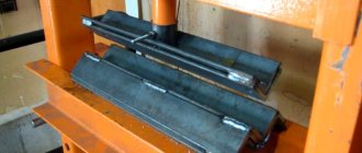
Manual lever press for forming fuel briquettes
Finally, let’s remember about independent procurement of alternative solid fuel. Fuel pellets, which produce the lowest ash content when burned, are formed in screw thermoforming installations of a rather complex design, see Fig. on right. Their disadvantage from the point of view of the owner is also significant energy consumption, which can negate savings on the purchase of standard fuel for a furnace or boiler.
It is much easier to build a wall-mounted manual lever press for manually pressing fuel briquettes from dry combustible agricultural waste, see next. rice.:
Diagram of a thermoforming installation for producing fuel pellets
For more information about its production, see the video in 2 parts:
Main varieties
A tabletop mechanical press is not the only type of manual pressing equipment. To perform various technological operations, specialists have created many different models of pressing equipment and manual devices, the most common of which are:
- manual hydraulic presses;
- hole-punching press devices;
- manual presses designed for connecting electrical cables mechanically;
- press pliers used for crimping electrical cables and plumbing pipes;
- tablet press
Manual hydraulic press for punching holes in metal sheets
Manual pressing equipment with hydraulic cylinders containing hydraulic fluid can generate forces that a screw or lever press cannot provide. The magnitude of such efforts in the case of using hydraulic equipment can reach tens of tons, while the user of such a device requires a minimal amount of labor. Hydraulic pressing equipment is used to solve the same problems as a conventional manual screw press or lever-type device, but only in cases where significant pressure must be applied to the workpiece.
Manual punching equipment is a device specifically designed for punching holes in sheet-type workpieces. You can also work with such devices on metal, if the thickness of the sheet does not exceed 4 mm. The diameter of the holes produced by this manual equipment can be in the range of 10–40 mm.
The DS-8 punching press cuts round holes with a diameter of 8 mm in metal up to 3 mm thick
Mechanical presses, designed for crimping electrical cable lugs and making their connections using special tubular sleeves, allow you to create connections that are not only characterized by high mechanical strength, but also excellent electrical conductivity. Such a manual pressing device, made in the form of a lever mechanism, is equipped with a ratchet, which prevents the compressing working elements from releasing until the cable crimping is completely completed. A press of this type can be used to work with electrical cables and wires of any type, the cross-sectional area of which does not exceed 240 mm2.
To crimp the sleeves of electrical wire lugs, manual press pliers with a ratcheting mechanism are used.
Press pliers are also used for crimping elements of electrical contacts, but such a manual mechanical press can be used for crimping electrical cables whose cross-sectional area does not exceed 35 mm2. The weight of tools of this type, to make them convenient to use manually, does not exceed 3 kg.
Hand press pliers for crimping small wire lugs
A manual tablet press is a device that is used to produce tablet medications in a laboratory setting. Devices of this type, with which it is possible to produce tablets with a diameter of 0.4–1 cm and a thickness of no more than 0.5 cm, can be manually, electrically or hydraulically driven. Depending on the model, the productivity of such equipment can be in the range of 200–1000 tablets per hour (and industrial models - up to 6000 tablets per hour and even higher). The maximum force that tablet presses are capable of creating, as a rule, does not exceed 700 kg.
Manual tablet press is used where granular powder needs to be compressed into tablets