A lathe is needed for the manufacture and processing of metal parts. Professional equipment is quite expensive, so in order to save money, you can make a homemade metal lathe with your own hands. This can be done in several ways, and drawings of such a product are easily found on the Internet. You can use improvised materials for production, but the size of the machine can be any.
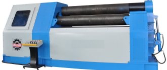
A professional lathe is expensive, so it makes sense to make such a device yourself
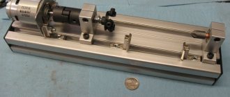
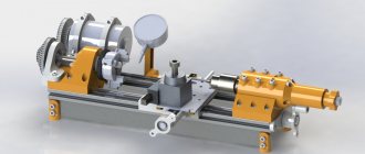
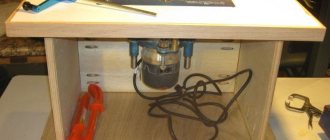
Homemade mini lathe from professional pipe (almost like a factory one)
In today's review, the author will share with us his personal experience of making a homemade mini lathe.
The basis of the machine is a square profile pipe 60x60 mm (wall thickness - 3 mm).
The dimensions of the professional pipe were not chosen by chance - it ideally fits a clamping chuck with a diameter of 16 mm. The result is a fairly compact headstock.
If you use a drill chuck with a diameter of 13 mm to make the headstock, then in this case you will need to use a 50x50 mm profile.
We also advise you to read: how to make a simple and compact machine for making clamps for reinforcement cages.
The length of the lathe bed is 22 mm, but if necessary it can be made longer.
Making the headstock of a lathe
We start by making the headstock. The drill chuck acts as a spindle.
A steel boss 30 mm long and 32 mm in diameter (internal diameter 17 mm) will need to be welded to the back of the drill chuck.
The author turned the outer surface of the boss on a lathe to a diameter of 30 mm for bearing 6906.
The protruding part of the steel boss has a diameter of 20 mm and serves as a seat for the gear.
The front part of the drill chuck must be turned on a lathe to a diameter of 35 mm - for bearing 6907.
We put all the parts together and get a fairly compact chuck-spindle (for our machine this is exactly what we need).
The headstock housing consists of three main parts:
- flange with a diameter of 80 mm;
- a piece of professional pipe 65 mm long;
- square plate 8 mm thick.
The flange has a centering rim for a 60x60 mm profile, which has a seat for bearing 6906.
A square metal plate is driven into the end of the profile pipe (body) and scalded.
In this plate you will first need to drill and then bore a hole for the front bearing.
Thick metal plates are welded to the headstock body, into which mounting holes are drilled.
Electrical equipment, light, lighting
Many men try to make a homemade lathe. The owners claim that working on a lathe allows you to enjoy the process of creating elegant things from raw materials. Not everyone can afford to buy a ready-made machine. Therefore, in this article we will look at how to make a homemade lathe.
Content:
Purpose of a lathe
The lathe is one of the first metalworking machines that was made primarily for processing products made of any material - wood, plastic and metal. Using such a machine, you can produce parts of various shapes by processing the outer surface, boring and drilling holes, cutting threads and rolling a corrugated surface.
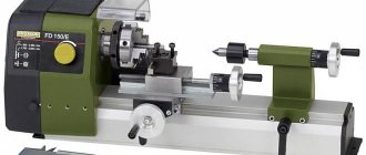
Manufacturers currently make a large number of different lathes. However, they are often too complex for homework, bulky and expensive. An excellent alternative to this is to make a homemade small lathe for wood or metal, which is convenient to use due to its small size and ease of operation and allows you to process small parts in the shortest possible time.
It’s good to have a wood lathe at home, with which you can turn small parts for furniture, handles for plumbing tools, and holders for household equipment. Starting with simple products, you can gradually work your way up to creating elegant, chiseled furniture sets and parts for sailing yachts. Using lathes, you can turn the necessary round parts: axles or wheels.
The principle of operation on such a lathe is quite simple: the workpiece, which is clamped in a horizontal position, is given a rotational movement, and excess material is removed by a movable cutter. However, to carry out these simple manipulations, a mechanism is required that consists of many parts that fit precisely together.
History of the lathe
Lathes have come a long way from being once primitive devices to becoming highly productive turning equipment. A couple of thousand years before our days, the simplest devices for processing wood and stone products and giving them a shaped and cylindrical surface were used in Ancient Egypt.
Main stages of work
In the bed of the lathe, the author cut a groove a little more than 10 cm long and about 8 mm wide. You also need to drill mounting holes according to the markings.
A strip of metal 8 mm thick is fastened inside the frame using M6 screws.
The craftsman drilled a series of holes in the profile pipe and the strip itself with a pitch of 20 mm. They are threaded M8.
The headstock is attached to the frame using four M6 screws. To tighten them, holes for a hexagon are drilled from the bottom of the frame.
It is also necessary to drill holes for M4 screws from the bottom of the frame. The base (steel plate 6 mm thick) is attached to the frame using screws.
Base dimensions - 220x95 mm. We drill mounting holes in the base for fastening to a table or other work surface.
The author made the next part from a turning tool (its width is 17 mm). This part is inserted into the frame and secured with four M4 screws.
Assembly instructions
To build a homemade metal lathe, it is best to start with the bed. On the upper edge of the base, seats are prepared for the longitudinal guides of the caliper, spindle, motor and other necessary elements. The leading requirement for these surfaces is to provide a reference plane for all equipment. The best approach would be to mill the sites using industrial equipment. It is advisable to immediately drill mounting holes on it. Otherwise, it will take much more time to install and align the guides.
The longitudinal guides of the support are attached directly to the base of the machine using screws. The lead screw bearing blocks are also installed there. During installation, ensure alignment of all elements. After the guides are finally secured, bearing modules are put on them. From above, on the mounting surface, the base of the transverse axis is attached. The latter uses a metal plate with mounting holes. The same plate is installed on the transverse movement bearings and serves to secure the tool holder. The homemade lathe will be completed by attaching miniature indicator dials and hand drive flywheels to the ends of the drive screws.
Manufacturing of longitudinal and transverse feed
The main part of the longitudinal feed is made of a profile pipe 80x80 mm (with a wall thickness of 4 mm).
A part of the wall with sides 10 mm high is cut off from the profile pipe, to which a cheek is welded on one side. We drill a hole with a diameter of 8 mm in the cheek - for the passage of an M8 thread.
In a part made from a turning tool, the author drills a hole coaxial with the hole in the cheek.
After this, the drilled hole will need to be drilled to a diameter of 14 mm and an M16 thread cut.
The author used an M16 thread so that the feed pitch was larger (1 turn - 2 mm).
The author attaches a square rod (adjustable clamp) to the movable platform (from the inside).
The author made a cross-feed base from a piece of 40x20 mm profile pipe. The slot in it is made for an M6 screw. An extended M8 nut is inserted and welded inside.
The cross feed screw is a piece of M16 pin. At the end there is a groove with a diameter of M8 for the handle of an old sewing machine.
The longitudinal feed is pressed against the frame using a homemade clamp, which is located inside the frame.
We install the longitudinal feed on the base and secure it. Next, the transverse feed is made using the same principle, but from a piece of 50x50 mm profile (wall thickness - 2.5 mm).
A 6 mm thick metal plate is attached to the top of the cross feed (used to secure the tool holder).
The cross feed lead screw is made from an M8 stud. A groove was made on one side and an M6 thread was cut for a homemade flywheel.
Assembly of all structural elements
We screw the frame to the base. We install the headstock, and then the longitudinal and transverse gears.
A 775 80W electric motor is used as a drive.
At the last stage, all that remains is to make the tailstock and secure it to the lathe bed.
A detailed review can be seen in the author's video (from YouTube channel IV I'm interested).
How to use a metal lathe
A modern industrial machine has a number of characteristics that allow it to perform many different operations. Such a device is equipped with a numerical program device and has a complex design. A DIY lathe does not require so many functions. It is enough to make a universal mechanical installation that will be conveniently placed on a table in the garage.
The main work performed on homemade milling equipment:
Safety precautions when working on lathes
- processing the internal surface, drilling the workpiece;
- turning a cone, groove;
- thread cutting;
- shaped turning;
- trimming ledges and sharp edges;
- turning of cylinders.
A metal lathe is used for machining nuts, bushings, couplings, pulleys, shafts and gears. From such parts, blanks are obtained that allow you to create or improve various mechanisms. Depending on the equipment used, the unit can process not only metal products, but also wooden or plastic blanks.
How to assemble the device
To assemble a metal lathe with your own hands, you need to follow these steps:
- Assembling a machine frame from beams and channel elements. If you intend to process large workpieces, use materials that can withstand significant loads. For example, if you want to process metal parts that are longer than 5 cm, the thickness of the frame materials should be at least 0.3 cm for the corners and 3 cm for the rods.
- Installation of longitudinal shafts with guides on channel elements. The shafts are connected using a welding machine or bolts.
- Making the headstock. For this, a hydraulic cylinder with a wall thickness of at least 0.6 cm is used. A pair of bearings must be pressed into it.
- Shaft routing. Bearings of large internal diameter are used.
- Filling the hydraulic cylinder with lubricant.
- Installation of the pulley and caliper with guides.
- Electric drive installation.
If you look at the drawings of a lathe, you will notice that to increase the stability of the cutter holder, a tool rest is used; a thin metal strip is fixed at the bottom of the unit. It is intended to protect the working part of the device from deformation when processing the workpiece.
Lathe design
A do-it-yourself metal lathe is a full-fledged piece of equipment with a power unit; it has a lot of weight and creates vibration. Before making such a device, it is necessary to carefully consider the design of all parts.
The mini-machine for home use has 4 main elements:
- Frame.
- Caliper and tool holder.
- Front and rear stock.
This unit is designed to fix all equipment in a rigid position. Being the basis, the frame must be strong and not distort. The machine can be placed on a table or a floor version can be made by increasing the length of the support. Such a cast frame is made from channels and metal corners. The frame elements are connected by welding or bolted.
Caliper
Such an element holds the cutting device and is capable of moving in a given direction and plane for efficient processing of workpieces. If it is necessary to create complex and non-standard surfaces, special attention should be paid to fastening this unit. For smooth movement in the horizontal direction, a screw mechanism in the apron is used. The support remains movable, but can be fixed if necessary. The cutters in the tool holder must be clamped tightly; backlash increases the risk of injury during operation.
Table of contents
Lathes are widely used in modern industry, for example, models such as the TV-320 screw-cutting lathe, as they allow you to perform many operations on processing cylindrical parts. Their design largely depends on the models, but there are always similar elements, since the main parts are the same for all, even if they have their own characteristics. The lathe support is one of the most important parts of the machine as it is responsible for mounting the cutter. It was its appearance that made a revolutionary step in machine tool building. This element is intended to move the cutting tool, which is located in the tool holder, when processing the workpiece in several planes.
photo: lathe support
Movement is carried out in three main directions relative to the machine axis:
Movements in given directions are carried out both manually and mechanically.
Lathe support device
photo: lathe support device
The lathe support has the following components:
- Lower slide (or longitudinal support);
- Lead screw;
- Cross slide (or cross slide);
- Rotary plate;
- Guides;
- Cutting head (tool holder);
- Screw;
- Fastening bolts;
- Fastening handle;
- Locking nut;
- Upper slide;
- Guides;
- Handle for moving the rotary plate;
- Handle for turning on automatic feeds;
- A handle that provides control of movement along the bed;
The principle of operation of the caliper
The support of a lathe has a very complex control system, since it includes many parts. Each of the elements performs its own function, ensuring the overall performance of the mechanism. For example, the support of a screw-cutting lathe has a lower slide No. 1, which can move along the bed guides during operation to get to the workpiece. Movement is regulated by handle No. 15. Thanks to movement on the slide, longitudinal movement along the workpiece is ensured.
The transverse support of the T3 lathe also moves on the same slide, which carries out transverse movements along its guides No. 12. Thus, all this covers the movement area, which lies perpendicular to the axis of rotation of the workpiece. By the way, if you are interested in the architectural design of buildings and structures, go to the website https://aec-project.ru/services/proektirovanie/.
On the cross slide there is a rotating plate No. 4, which is attached to it with a special nut No. 10. Guides No. 5 are installed on the rotating plate, along which the upper slide No. 11 runs. The upper slide is controlled using the rotary handle No. 13. The upper slide rotates in a horizontal plane simultaneously with the plate. It is this unit that ensures the movement of the cutter, which is carried out at an angle to the axis of rotation of the part.
The cutting head, or as it is also called - the tool holder, No. 6 is fixed on the upper slide using special bolts No. 8 and handle No. 9. The movement from the caliper drive is transmitted through lead screw No. 2 to the drive shaft, which is located under this same screw. This can be done either automatically or manually, depending on the model.
Basic caliper movements
- Transverse movement is carried out perpendicular to the axis of rotation of the workpiece and is used in cases where it is necessary to machine something deep into the surface of the workpiece;
- Longitudinal movement is carried out along the workpiece and is used in cases where it is necessary to remove the top layer or grind a thread on the workpiece;
- Inclined movement is carried out along an inclined plane and significantly expands the processing capabilities of this equipment.
Adjusting the lathe slide
The support of a lathe wears out during its operation and requires adjustment of individual parts to continue working correctly:
- Adjusting the gaps. As the slide guides wear, a gap appears that should not exist. Its appearance can cause interference in the uniform movement of the sled, jamming in one place and lack of swaying when lateral forces are applied. To correct this situation, it is necessary to move the guides to the proper position and eliminate the excess gap. This is done using wedges, and the carriage is pressed against the guides.
- Backlash adjustment. If play appears in the screw drive, it can be easily eliminated by adjusting the fastening nut located on the device.
- Adjusting the seals. During prolonged work at the ends of the carriage protrusion, the seals become clogged and worn out, which can be easily seen by the appearance of dirty streaks that remain when the frame moves. In this case, to adjust the device, you should wash the felt padding and then soak it in oil. If it is completely worn out, it is easier to replace it with a new one.
Step-by-step assembly of turning equipment with your own hands
A homemade lathe consists of parts that can be found in a garage or workshop. Before proceeding with the processing and assembly of the device, it is necessary to carefully consider the design and characteristics of the unit, its location in the workshop.
Necessary materials
You can use available materials as materials:
- welded frame (replaces the cast frame);
- power unit - any motor with an electric drive with a power of 800-1500 W from household appliances (a good option is an asynchronous motor);
- Belts of different lengths can be used as a driving stone;
- screws and nuts for fastening the structure;
- guides, slides made of steel rod;
- spindle and tailstock (it is better to find ready-made parts, but you can make them from a profile pipe or a piece of metal sheet);
- feed screws - for a do-it-yourself lathe, long rods with threads in the longitudinal and transverse directions are suitable;
- rolling bearings as rotation elements;
- squalls of different diameters;
- a steel plate with a thickness of at least 8 mm - for the caliper and tool holder.
Where to get a lathe project
Standard dimensions of turning equipment: 115x62x18 cm. Such parameters are considered optimal for work.
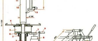
Drawing of a homemade lathe
Manufacturing process
Making a metal lathe with your own hands is carried out in accordance with the step-by-step guide for the main components:
The figure shows where and in what place the parts should be located correctly
- Formation of the frame according to the drawing data. The pipes are cut and welded together; it is important that the corners are even.
- Creating side posts (for this it is better to use another milling machine).
- Assembling the support unit, connecting the posts with the guides, installing spacer bushings on the sides.
- Fixing bushings for the tailstock. If you use these parts of different sizes, you can achieve more stroke.
- Creating a platform for the support.
- Mounting the lead screw, attaching the steering wheel and vernier to it.
- Installation of the headstock platform.
- Attaching the headstocks to the machine.
- Creating a support and tool holder.
- Formation of the engine subframe.
- Installation of the power unit and its connection to the electrical network.
- Test run at idle.
A DIY metal lathe is quite easy to make. It is important to maintain the design parameters, ensure a rigid connection and select a suitable electric motor.
Rules for using the equipment
After completing the assembly, you need to check the equipment with a test run.
Everything is fine? Then study the following operating rules:
- Choose the right workpiece. It should not have cracks or be knotty.
- Securely secure the workpiece before working with it.
- Be sure to check the grounding before turning on the machine.
- Use a protective screen and a change of protective clothing.
- Check the tool before starting work for integrity and secure fastening. Correct any defects found immediately.
- Use wood whose moisture content does not exceed 20%.
- Save the machine drawings.
- Place a rubber mat under your feet every time.
How to make a homemade support for a lathe with your own hands?
In metal work, a lathe is used to produce cylindrical (conical) shaped parts. There are many models of this production device, and all of them have almost the same layout of similar components and parts. One of these is the machine support.
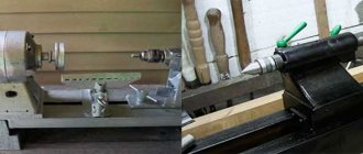
Homemade lathe
To better understand the functions performed by a lathe support, you can consider its operation using the example of the common 16k20 model. After reading this information, perhaps some home craftsmen will have the idea to create a homemade lathe for metal work with their own hands.
What can be done with a mini-lathe, and where is it used?
Household mini-lathes, like similar industrial equipment, are designed for processing metal workpieces and giving them cylindrical, conical and spherical shapes. Nowadays, almost all industries use CNC units, which makes it possible to reduce human participation to almost zero, but for home needs a simple machine is suitable. Despite the fact that compact turning equipment has inherited most of the functions from its larger counterparts, however, it can only be used to process small workpieces and parts. Also, on mini-machines you can perform end cutting and drilling, perform external and internal threading, boring and much more. Compact turning equipment is perfect for a garage, home, installation on a balcony or in a small workshop.
§ 21. Techniques for working on a screw-cutting lathe
One of the most common turning operations is the machining of external cylindrical surfaces. It is performed with passing incisors.
The workpiece must be fixed in the chuck so that its overhang is 7.12 mm greater than the required length of the part. This allowance is necessary for processing the ends and cutting the part.
The spindle rotation speed and depth of cut during turning are indicated in the technological map.
When setting the cutting depth, use the cross feed dial. In the TV-6 screw-cutting lathe, when this dial is rotated by one division, the cutter will be fed to a cutting depth equal to 0.025 mm (i.e., the price of dividing the transverse feed dial is 0.025 mm). The diameter of the outer surface of the part will decrease by 0.025 x 2 = 0.05 mm. The total number of divisions of the cutter feed dial α is determined by the formula: αtransverse = (D - d): 0.05, where D is the diameter of the workpiece, d is the diameter of the part.
After turning the outer cylindrical surfaces, the end of the workpiece is often trimmed. For this, various cutters are used.
When cutting the end with a passing (Fig. 72, a, b, c) or scoring (Fig. 72, d) cutter, bring it into contact with the end, then pull it back and move the carriage 1.2 mm to the left (i.e. set the cutting depth to 1.2 mm). By moving the cutter transversely, a layer of metal is removed from the end. You can move the carriage by 1.2 mm or any other amount using the longitudinal feed dial. The division price of this dial is 0.5 mm, therefore the number of divisions by which the dial needs to be rotated is determined by the formula: αlongitudinal = l: 0.5, where i is the required length of movement of the carriage.
Rice. 72. Trimming the ends with passing (a, b, c) and scoring cutters
If there is a hole at the end of the part, then trimming the end can be done from the center of the part by moving the cutter toward you (Fig. 72, c).
When processing small ledges, turning and trimming are performed with one persistent cutter.
External grooves are cut using slotted (groove) cutters. In this case, the cutting speed is set four to five times lower than when cutting the ends. The cutter is installed in the required place and smoothly, without much effort, moved in the transverse direction, removing chips. The depth of the groove is controlled by the transverse feed dial.
When cutting workpieces, they act in the same way as when cutting grooves. Finish cutting when the diameter of the jumper becomes equal to 2.3 mm. Then the machine is turned off, the cutter is removed from the slot and the part is broken off.
When processing parts on lathes and other machines, part of the metal turns into chips. At enterprises, the shavings are not thrown away, but are crushed in special devices and pressed into briquettes. These briquettes, together with scrap metal, are used in the smelting of steel and other metals and alloys.
Safe work rules
- You can measure the dimensions of the part, remove chips, clean and lubricate the machine only after it is completely turned off.
- The shavings should only be removed using a hook and brush.
Practical work No. 21
Grinding the outer cylindrical surface of a workpiece on a TV-6 machine
- Place and secure the workpiece in the chuck and the through cutter in the tool holder.
- Move the cutter towards the workpiece so that its tip is to the left of the end of the workpiece by 8.10 mm and at a distance of 2.3 mm from its surface.
- Turn on the spindle rotation and carefully move the cutter towards the workpiece until a slightly noticeable circular mark appears on its surface. Move the cutter to the right at a distance of 8.10 mm from the end of the workpiece and turn off the machine.
- Holding the handle for transverse movement of the caliper with your left hand, turn the dial ring with your right hand until its zero line aligns with the mark on the fixed bushing.
With both hands, turn the handle for transverse movement of the caliper to the required number of dial divisions (pre-calculated by you).
- Turn on the spindle rotation. Grind the workpiece to a length of 3.5 mm with manual feed of the caliper. Move the cutter away from the workpiece by turning the cross feed handle counterclockwise half a turn and move it to the right to its original position.
- Turn off the machine and measure the resulting diameter of the workpiece with a caliper. If the diameter is larger than required, calculate how many divisions you need to move the cutter to get the required diameter. Turn on the machine and remove chips in a test area. Repeat these steps until you reach the desired size.
- When you obtain the desired diameter, grind the workpiece along its entire length using manual or mechanical feed of the cutter. Move the cutter away from the surface being processed towards you and to the right to its original position.
Practical work No. 22
Trimming the end and drilling the workpiece on a TV-b machine
- Install and secure the cutter in the tool holder.
- Turn on the machine and trim the end of the workpiece (see Fig. 72) using the cross feed of the cutter. Turn off the machine, remove the part, secure it in a vice and clean the resulting ledge in the center of the end. Check the straightness of the end by applying a ruler to it.
- Install the part into the three-jaw chuck of the machine. Attach a center drill bit (or a short small diameter drill bit) to the chuck mounted in the tailstock quill. Turn on the machine and, rotating the tailstock flywheel, drill (center) the end to a depth of 2.3 mm. Remove the chuck from the tailstock quill.
- Install and secure the twist drill bit into the tailstock quill. Mark the required drilling depth with chalk on the drill bit. Turn on the spindle rotation and drill a hole in the workpiece to the specified depth by rotating the tailstock handwheel clockwise. Remove the drill from the hole and turn off the machine.
- Measure the depth of the drilled hole.
Şərh • 40
Maybe it’s worth turning it over so that the chips don’t get stuffed inside
a lot of letters, and a lot of fingers))) “friend-friend” - “brother-brother”)))
What happened as a result. Can I have a video of how the machine sharpens?
There are plenty of them, look for them on my channel
Not only collective farms. State farms too, everything will be fine, everything will be fine, everything will be fine, I know, I know, I know, I know, I know, I know, I know, I know, I know, I know, I know, I know, I know, I know, I know, I know, I know, I know, I know. I know I know I know I know I know I know I know I know I know
Work worthy of respect. I wish you success and health.
In my case, on the rods of the shock absorber, 20mm on a cut, how did you do it?
+Vladyk Naz just bought a channel for the bed today. There is a video, I'll start collecting it
What did you use to cut the plate out of the slab? Somehow too smooth for a simple grinder.
I also made a dovetail from a corner, vibration appeared almost immediately. As I understand it, plain metal is still not suitable for the loads of a lathe. My advice is, you shouldn’t waste money, effort and nerves on a homemade lathe, no matter how much you would like to make it yourself. It's better to buy a factory one. This is my personal experience. and I wish you good luck
so that the metal does not move when welding long seams, the seam must be welded in a REVERSE STEP method “weld a few cm, step back a few cm and weld back to the welded seam, etc.
Alim, where is the continuation? I want to see what happens. I did it on shock absorber struts, so at 200 rpm it crushes on blanks over 30 mm. It jumps like on springs. I'm thinking about how to make the tails.
car shock absorbers, the rod itself is used.
What kind of shock absorbers are they from?
Kirill Gaidukovich there is no continuation yet unfortunately
idea 5 execution 2 as they say. Very flimsy, especially the base of the flipper and tail. on steel he will vomit immediately.
Yuriy Klevchuk won’t throw up right away, but if something happens we’ll strengthen it. I am making a machine for myself, I will not make money from it. Everything will get stronger along the way, work will show
and if you add clamping bolts through a powerful spring, vibrations will be dampened. but you will have to make more passes.
An interesting approach to the solution. ) But I would do one more thing: 1. I would place a sanded strip(s) (for example, from wood planing knives) between the moving part and the fixed part and tighten them with bolts (with a lock nut) - to reduce friction forces, to remove gaps and make it easier installation work 2. Transverse welded ribs on inclined fixed plates (dovetail) - so that the plates do not bend. 3. I would definitely install the dial on the transverse screw - practice shows that without it it’s difficult to make anything more precise than a millimeter (if you don’t use additional stops, of course.) I wish you good luck!
§ 21. Techniques for working on a screw-cutting lathe
One of the most common turning operations is the machining of external cylindrical surfaces. It is performed with passing incisors.
The workpiece must be fixed in the chuck so that its overhang is 7.12 mm greater than the required length of the part. This allowance is necessary for processing the ends and cutting the part.
The spindle rotation speed and depth of cut during turning are indicated in the technological map.
When setting the cutting depth, use the cross feed dial. In the TV-6 screw-cutting lathe, when this dial is rotated by one division, the cutter will be fed to a cutting depth equal to 0.025 mm (i.e., the price of dividing the transverse feed dial is 0.025 mm). The diameter of the outer surface of the part will decrease by 0.025 x 2 = 0.05 mm. The total number of divisions of the cutter feed dial α is determined by the formula: αtransverse = (D - d): 0.05, where D is the diameter of the workpiece, d is the diameter of the part.
After turning the outer cylindrical surfaces, the end of the workpiece is often trimmed. For this, various cutters are used.
When cutting the end with a passing (Fig. 72, a, b, c) or scoring (Fig. 72, d) cutter, bring it into contact with the end, then pull it back and move the carriage 1.2 mm to the left (i.e. set the cutting depth to 1.2 mm). By moving the cutter transversely, a layer of metal is removed from the end. You can move the carriage by 1.2 mm or any other amount using the longitudinal feed dial. The division price of this dial is 0.5 mm, therefore the number of divisions by which the dial needs to be rotated is determined by the formula: αlongitudinal = l: 0.5, where i is the required length of movement of the carriage.
Rice. 72. Trimming the ends with passing (a, b, c) and scoring cutters
If there is a hole at the end of the part, then trimming the end can be done from the center of the part by moving the cutter toward you (Fig. 72, c).
When processing small ledges, turning and trimming are performed with one persistent cutter.
External grooves are cut using slotted (groove) cutters. In this case, the cutting speed is set four to five times lower than when cutting the ends. The cutter is installed in the required place and smoothly, without much effort, moved in the transverse direction, removing chips. The depth of the groove is controlled by the transverse feed dial.
When cutting workpieces, they act in the same way as when cutting grooves. Finish cutting when the diameter of the jumper becomes equal to 2.3 mm. Then the machine is turned off, the cutter is removed from the slot and the part is broken off.
When processing parts on lathes and other machines, part of the metal turns into chips. At enterprises, the shavings are not thrown away, but are crushed in special devices and pressed into briquettes. These briquettes, together with scrap metal, are used in the smelting of steel and other metals and alloys.
Safe work rules
- You can measure the dimensions of the part, remove chips, clean and lubricate the machine only after it is completely turned off.
- The shavings should only be removed using a hook and brush.
Practical work No. 21
Grinding the outer cylindrical surface of a workpiece on a TV-6 machine
- Place and secure the workpiece in the chuck and the through cutter in the tool holder.
- Move the cutter towards the workpiece so that its tip is to the left of the end of the workpiece by 8.10 mm and at a distance of 2.3 mm from its surface.
- Turn on the spindle rotation and carefully move the cutter towards the workpiece until a slightly noticeable circular mark appears on its surface. Move the cutter to the right at a distance of 8.10 mm from the end of the workpiece and turn off the machine.
- Holding the handle for transverse movement of the caliper with your left hand, turn the dial ring with your right hand until its zero line aligns with the mark on the fixed bushing.
With both hands, turn the handle for transverse movement of the caliper to the required number of dial divisions (pre-calculated by you).
Practical work No. 22
Trimming the end and drilling the workpiece on a TV-b machine
- Install and secure the cutter in the tool holder.
- Turn on the machine and trim the end of the workpiece (see Fig. 72) using the cross feed of the cutter. Turn off the machine, remove the part, secure it in a vice and clean the resulting ledge in the center of the end. Check the straightness of the end by applying a ruler to it.
- Install the part into the three-jaw chuck of the machine. Attach a center drill bit (or a short small diameter drill bit) to the chuck mounted in the tailstock quill. Turn on the machine and, rotating the tailstock flywheel, drill (center) the end to a depth of 2.3 mm. Remove the chuck from the tailstock quill.
- Install and secure the twist drill bit into the tailstock quill. Mark the required drilling depth with chalk on the drill bit. Turn on the spindle rotation and drill a hole in the workpiece to the specified depth by rotating the tailstock handwheel clockwise. Remove the drill from the hole and turn off the machine.
- Measure the depth of the drilled hole.