Archive for machines
The universal horizontal boring machine 2A614-1 is designed for processing body parts with precise holes. interconnected by exact interaxal distances.
The largest mass of processed parts is 2000 kg.
The 2A614-1 machine, unlike the 2A615-1 machine, is equipped with a built-in faceplate with a radial support.
The machines have great versatility. They can be used for drilling, boring, countersinking and reaming holes, milling planes and grooves, as well as turning ends, boring holes and processing annular grooves with a radial support of the faceplate.
- The 2A614-1 machine, upon customer request, can be manufactured with a thread-cutting device.
- The presence of a mechanized tool clamp, rigidity, vibration resistance, speed and ease of control of the machine make it possible to carry out precise productive processing on them with the least amount of machine and auxiliary time.
- The machines are designed for use in tool and machine shops.
Technical characteristics of horizontal boring machine 2A614-1
Technical characteristics of machines are the main indicator of the suitability of a machine for performing certain jobs on machines. For horizontal boring machines, the main characteristics are:
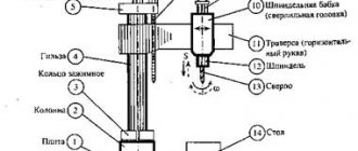
- Table work surface size
- Retractable spindle diameter
- Maximum longitudinal movement of the spindle
- Spindle revolutions per minute
Below is a table with the technical characteristics of the 2A614-1 jig boring machine. More detailed technical characteristics of the machine can be found in the passport of the machine 2A614-1 located below.
| Name of parameters | Unit. | Quantities |
| Machine accuracy class according to GOST 8-77 | N | |
| Retractable spindle diameter | mm | 80 |
| The end of the retractable spindle with a cone for holding the tool | 40AT5, Morse 5 | |
| Built-in turntable dimensions (L x W) | mm | 1000×1000 |
| Vertical movement of spindle head | mm | 800 |
| Longitudinal movement of the retractable spindle | mm | 500 |
| Longitudinal movement of the built-in rotary table | mm | 1000 |
| Lateral movement of the built-in rotary table | mm | 1000 |
| Radial movement of the built-in faceplate support | mm | 125 |
| Retractable spindle speed | rpm | 20…1600 |
| Faceplate rotation speed | rpm | 6,3…200 |
| Feed limits of working bodies | mm/rev | 0,02…8 |
| Feed limits of the retractable spindle, spindle head, table in both directions. | mm/min | 1,26…2000 |
| Feed limits of the built-in faceplate caliper | mm/min | 0,5…800 |
| Speed of fast installation movements of the retractable spindle, headstock, table | mm/min | 5000 |
| Speed of fast installation movements of the built-in faceplate caliper | mm/min | 2000 |
| Maximum permissible torque on the retractable spindle | Nm | 865 |
| Maximum permissible torque on a triple faceplate | Nm | 1300 |
| Maximum permissible spindle feed force | kN | 7,5 |
| Maximum permissible table feed force | kN | 10 |
| The largest mass of the processed product | kg | 2000 |
| Overall dimensions of machines without attachments (LxWxH) | mm | 4518x2590x2585 |
| Weight of machines without electrical equipment and accessories | kg | 8500 |
CNC: classification and explanations
Today CNC is used everywhere in machine tools, with the only caveat that it is strictly for technological needs: if it is possible to make a part, and there are no requirements for super-precision of its execution, you can simply invite an experienced craftsman to work on it, who will carry it out on a familiar manual machine.
Although for home work (for jewelers, wood and metal artists) there is a miniature tabletop machine, it is no less professional and reliable.
Video:
So the price and the question of appropriateness, although banal, are vital. Technologically, the CNC system can be divided into 2 groups:
- Positional: the drill and the workpiece move intermittently - point by point. In this case, the positions are either far away (say, when boring and drilling), or close to each other (as when turning and milling);
- Continuous movement: contour work in one movement.
The CNC positional system is the simplest type of control, but is used mainly in drilling and jig boring machines, where shaped movement is not required - only in a straight line.
The rectangular CNC system moves the drill one at a time along a specific coordinate axis, while the speed of movement is set by the program itself.
This system is also used to a limited extent (comparatively) on workpieces that can be placed parallel to the coordinate axes (turning, milling).
CNC shaping
This type of CNC needs to be discussed separately. This is a more advanced option for positioning and work in general, since the tool moves along two or more coordinates, which allows processing workpieces of any shape.
The interpolator simultaneously produces coordinates in three-dimensional space in the form of a certain number of feed drives. Today, more and more machines are being produced with CNC shaping.
Video:
Yes, they are expensive, but such professional equipment quickly pays for itself, as it allows you to produce complex parts that are not cheap.
But even such an innovative machine can offer a choice of options: 2D and 3D shaping.
2D shaping is controlled along two coordinate axes, which means you can move the drill along an arc and a straight line. A particular version of this type is 2½D shaping.
IMPORTANT TO KNOW: Operation of CNC milling machines for metal
The drill already moves along 3 coordinate axes, but the difference is that only 2 axes are controlled, and the third is used for installation, approach and retraction of the tool.
After executing a command to move in a certain plane, the system can switch to movement in another.
The current processing plane, coupled with the simultaneous control of different axes, allows the drill to operate in the XY, XZ, YZ planes.
This CNC system is used in simple machines that are equipped with a stepper feed drive.
What is noteworthy is that complex contours and surfaces can be processed on the machine, but a volumetric part is processed layer by layer in a specific vertical or horizontal plane, and not continuously.
3D shaping is the crown of machine tool engineering, which produces high-precision parts with a smooth surface.
Video:
The machine tool moves along 3 axes at once, which means you can process any spatial contour continuously. For the most part, the milling method is used rather than drilling.
However, if the machine is universal, and even with 3D, then it will perform any part, not to mention ordinary drilling. The price of such a unit sometimes reaches several thousand euros.
Passport 2A135 (Ø 35 mm) Universal vertical drilling machine (Sterlitamak)
Name of publication: Description and maintenance manual Publication issue: Sterlitamak Machine Tool Plant named after Lenin Year of publication: 1960 Number of books (folders): 1 Number of pages: 31 Cost: Negotiable Description: Complete set of documentation
Description of the machine: The passport of the machine 2a135 is, albeit a rather rare publication, but nevertheless in demand for the operation and maintenance of a drilling machine of this model. It’s no secret that the 2A135 was produced at one time at an enterprise called the Sterlitamak Machine Tool Plant and was at that time an updated piece of equipment that replaced the equally well-known at that time, but more outdated machine model 2135. The presented drilling machine, in its updated configuration would be more productive in terms of working with metal, universal and unpretentious, which recommended this position to a wide variety of industrial enterprises with the highest quality supply. And this is not surprising, because the new design of the machine has acquired the most convenient way to control it, which certainly improved the ergonomic performance of the piece of equipment as a whole. At the same time, the machine works remarkably well with a drilling diameter of 35 millimeters, which allows it to cover a fairly wide range of metalworking capabilities, and this is actually an important aspect for any enterprise of one or another production focus.
The documentation for the machine itself is designated as a description and operating manual, which contains quite a lot of theoretical and, of course, practical information bordering on it. The fact is that theory is certainly a key factor for the concept of operating principles on any model of machine tool equipment, and these points were of course understood and taken into account by the machine developers, which were subsequently presented in the form of a detailed publication. In addition, moving from an operational focus to a focus related to the maintenance of machine equipment, here it is necessary to be guided not only by theory, but also by a practical approach to interaction on a drilling machine. And practice is the presence of all the necessary drawings and diagrams, on the basis of which the most productive option for working with the position of the equipment is possible. And just in the presented publication, of course, there are all the components necessary for production activities. These are circuits associated with both the mechanical and electrical parts of the machine. After all, the electrical equipment section is very important for working with electrical equipment that is located in the electrical cabinet, and the moments of restoration and even repair contribute to detailed information on the electrical circuit.
At the same time, in the manual you can find a number of drawings that influence the direction of the most rational work with the mechanics of the machine. These drawings have both general parameters and more detailed ones, which are designated as drawings of spare parts. In general, the documentation is a copy of the original and was translated by us into electronic format, which has high resolution and, of course, the possibility of a readable result when studying this technical literature. For this reason, it is possible to download a drilling machine passport from our electronic archive immediately after payment and receipt of the payment into our account. And we will be happy to provide a service in the direction of providing this or that documentation of interest, which is available in the company’s archive. In that case, if we consider such an important point as the use of 2A135 in production conditions, then the machine has the ability to process parts or workpieces that are quite small in size and weight associated with a metal base. And the machine itself can be successfully and actively used in small-scale production, repair, as well as tool shops of a wide variety of organizations related to the technological features of the industrial sector.
Designation
Soviet-made equipment is designated according to the ENIMS classification.
The first number indicates the equipment group, the second the type of drilling machine, the third and fourth - the maximum drilling diameter. The letter in the abbreviation indicates the modernization carried out. For example, 2M112 - the machine belongs to the drilling group, M - modernization was carried out, 1 - vertical drilling machine, 12 - maximum drilling diameter in steel is 12 mm.
Modern imported machines do not have a marking standard. Each manufacturer introduces its own labeling standard and adheres to it in its line of equipment. This point complicates the selection, because Its characteristics are not always clear from the name of the machine.
Techniques for drilling difficult-to-cut alloys
Difficult-to-process alloys include heat-resistant, titanium, stainless steels, etc. When drilling them with a standard drill, highly deformed strip chips are formed, wedged in the grooves of the drill, causing the occurrence of large cutting forces. This entails an increase in drill vibrations, which has a detrimental effect on the condition of its cutting edges, which quickly become dull. Therefore, difficult-to-cut alloys should be drilled taking into account the following recommendations:
- 1. Use special shortened (compared to standard) drills, the length of which should not exceed their diameter by more than 4-5 times.
- 2. Do not use drills that have been shortened as a result of regrinding standard drills. Shortening a standard drill results in an increase in the length of the transverse cutting edge due to the fact that the thickness of the bridge increases as it approaches the shank.
- 3. In the absence of special shortened drills, it is possible to put on and fasten rigid split bushings with an internal diameter equal to the diameter of the drill and an external diameter equal to 35..60 mm onto standard drills. The bushing must be secured close to the end of the chuck or machine spindle. The length of the sleeve depends on the length of the drill, but it is desirable that the part of the drill protruding from the sleeve does not exceed the diameter of the drill by more than 5..6 times.
- 4. To increase the durability of the drill, the width of its guide strips should be reduced to 0.2..0.4 mm, the clearance angle should be increased to 12° and double sharpening should be used.
- 5. To prevent jamming of chips, chip separating grooves should be cut on the rear surface of the drill (Fig. 86), dividing the chips widthwise into several parts; this improves the conditions for its removal from the hole.
- 6. To prevent chips from wrapping around the drill when leaving the hole, use a special chip breaker, which is a conical cap attached to the drill. The shavings, resting against the cap, break into short spirals.
- 7. Drilling should be carried out only with the use of cutting fluids. For heat-resistant alloys, a 50% emulsion or aqueous solution of barium chloride with the addition of 1% sodium nitrate is recommended; for titanium alloys, castor and sulfur oils, oleic acid or mixtures thereof are recommended.
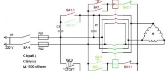
Electrical equipment and electrical circuit of the drilling machine 2N118
Electrical diagram of drilling machine 2n118
The electrical equipment of the machine contains:
- spindle rotation electric motor 1M;
- electric cooling pump 2M;
- start-up and automation equipment;
- selenium rectifier SV;
- local lighting.
Control of drilling machine 2N118
The following controls are installed on the machine:
- control buttons - “Left”, “Right” and “Stop”;
- introductory machine;
- manual starter for turning on the cooling pump with “Start” and “Stop” buttons.
Braking the spindle of the machine 2N118
The machine uses a dynamic braking circuit with direct current supplied to three phases of the stator winding through the contacts of the SC brake starter from a selenium rectifier SV, which is powered by a step-down transformer TBS2-01. Simultaneously with the supply of DC current during braking, the stator winding is short-circuited in two phases for better braking efficiency. Braking occurs only when the ZKU or 2VK button is pressed.
Operation of the electrical circuit of the 2N118 machine
By pressing the 1KU “Right” button, the K1 starter is turned on, which is self-blocking with block contacts 6-7, and with contacts 4-16 it turns on the intermediate relay RP, which with its contacts 4-16 will become self-powered, and with contacts 14-9 it prepares the switching on of the K2 starter, if During operation on the machine, spindle rotation is reversed by pressing 1VK.
By pressing the 2KU “Left” button, the K2 starter is turned on, which is self-blocking with block contacts 4-9.
Whenever the spindle rotates to the right, left, pressing the “Stop” button, braking is performed, and K1 and RP are turned off if there was a rotation to the right, or K2 if the rotation was to the left. Through contacts 13, 17, 18, the short-circuit braking starter will turn on, which supplies direct current to the stator winding of the electric motor, and the engine will brake.
Protection
The electric motor is protected from overloads and short circuits by an AST-3 automatic switch. Zero protection is provided by a coil of magnetic starters.
The machine must be grounded in accordance with existing rules and regulations.
Equipment characteristics
Component Layout
The main parameters of the machine are described in detail in its passport and technical documentation. To operate the equipment, you should know that the maximum drill hole diameter can be 25 mm (for parts made of steel 45). In this case, the characteristics of the distance limits from the surface of the work table to the spindle cone range from 6 to 70 cm.
The large mass of the machine, 880 kg, gives the entire structure maximum stability and is the main factor in damping vibrations that occur during operation. At the same time, the dimensions of the structure allow it to be installed in the limited space of a production or repair shop. They measure 235*78.5*91.5 cm.
But the main passport characteristics of the 2N135 machine are the spindle parameters:
- maximum vertical movement – 17 cm;
- stroke – up to 20 cm;
- with one revolution of the flywheel, a displacement of 122.46 mm occurs;
- the number of speeds is 12;
- permissible torque is 250 Nm;
- the cone corresponds to Morse parameter 3.
The 2n135 machine has 12 feed stages. In this case, the vertical limits range from 0.1 to 1.6 mm with one spindle revolution. The design of the 2N135 machine is designed for manual control only.
Drilling equipment
In the machine park, a large percentage is occupied by the segment of drilling machines. This is explained by the need to carry out drilling in almost any technological process. All the necessary information related to the design of the unit is contained in the passport supplied with any model of the unit.
All equipment in this segment consists of three groups, each of which is distinguished depending on the specifics of the work:
- special;
- specialized;
- universal.
In each of these groups, gradation can be made depending on the size of the drill, and, accordingly, the holes that a given drilling machine can handle. Let's highlight the main ones:
- light, up to 12 mm;
- medium, 18-50 mm;
- heavy, over 50 mm.
Design features
The design of the drilling machine consists of:
- The working head, which serves to secure the tool.
- Drive unit.
- Plunger type oil pump.
- Cooling system for the treated area.
- Spindle.
- Gearbox.
- Unit power supply system, electrical cabinet for connecting to the network.
- Gearbox.
- Speed and feed control system.
- Base plate, column, work table.
The unit frame is made in the form of a monolithic, massive, cast-iron structure. The position of the productive surface is carried out by the operator on the supporting column manually, by pressing the locking device and turning the steering wheel, which performs the function of adjusting the position of the spindle. To move the table surface, special guide grooves are made on the column.
The base plate is also cast iron. It has a hollow structure, inside of which there is a container for storing cooling liquid. There is also a settling tank for large metal contaminants and a filtration device. On the support column itself there is an electric pump with a power of 120 W, which is responsible for supplying the liquid. The coolant is supplied through a system of tubes of various diameters, which supply water directly to the drilling element.
The power unit of the machine is located on the top of the body. The spindle block and gearbox of the machine are located in the housing. The kinematic diagram of the equipment has a simple design solution, in which the power unit and the speed box are connected by a straight shaft. Mechanical speed adjustment is carried out using a handle located on the front side of the drilling head. Speed adjustment is done manually. The box transmits spindle rotation speed at twelve frequencies.
The operating elements of the unit are lubricated using a plunger pump in automatic mode. The operator will only need to monitor the oil level using the sensor located on the front panel.
This model has a manual spindle feed system. This system includes:
- A steering wheel that performs an adjustment function.
- Worm-like transmission.
- Overrunning ratchet and dog clutch.
- Limba.
- Shaft, horizontal, with rack and pinion gear.
Features of the 2N135 machine
The model of the 2N135 vertical drilling machine, characterized by a nominal drilling diameter of 35 mm, was once designed and developed by specialists from the Odessa Design Bureau. The production of the 2N135 machine tool, which was equipped mainly with small enterprises, was carried out by the machine-tool plant in Sterlitamak. Several other types of machines produced by the following enterprises have similar technical characteristics to this model:
- Sterlitamak Machine Tool Plant (2S125, 2S125-01, 2S125-04, 2N132, 2S132);
- Gomel plant of machine components (2T140, 2TS140);
- Kiev Machine Tool Plant (KA-232);
- Krasnorechensky Machine Tool Plant (2N135L);
- in Bulgaria (RK032).
Vertical drilling machine 2T140
The 2N135 machine was used as the basis for the creation of new, more improved equipment. On its basis, in particular, the following machine models were developed:
- 2N135-1 and 2N135K – a coordinate vertical drilling machine and a model equipped with a round rotary table;
- 2Р135Ф2 – automated drilling machine, equipped with a turret head and a cross table (the operation of this machine in automated mode is ensured by a CNC system);
- 2N135S – vertical drilling machine with a quill on which a working head with several spindles can be mounted;
- 2N135A is another automated model of the machine, control of which is provided by a system of buttons and cams;
- 2N135N is a multi-position machine, which, depending on the need, can be equipped with rotary tables and working heads with several spindles.
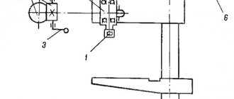
Location of the main parts of the drilling machine 2N135
The technical capabilities of the 2N135 machine are provided, first of all, by the features of its design, consisting of such elements as:
- working head in which the tool is fixed;
- plunger type oil pump;
- drive unit;
- a system that provides cooling of the processing area;
- gearbox;
- spindle;
- elements of the machine's power supply system, including the electrical cabinet;
- gearbox;
- elements of a system that provides control over feeds and speeds;
- desktop, base plate, column.
The characteristics of the 2N135 machine indicate its high versatility. With its help, you can process workpieces made of different materials and with sizes in a fairly wide range. The variability of materials that can be processed on this machine is achieved through the use of tools made from high-speed steels or alloys with high hardness.
2N135 machines are easy to use due to the fact that, using the feed box and spindle speeds, you can select optimal modes for producing and processing holes with various parameters and in materials with different characteristics. What’s noteworthy is that 2N135 machines can also be used for cutting threads using machine taps. The implementation of such a technological operation becomes possible due to the fact that the machine spindle can rotate in both directions, for which a special reversing mechanism is responsible.
Vertical drilling machines 2N135 are distinguished by the following design features and technical characteristics:
- the distance between the axis of the vertical spindle and the guides is 300 mm;
- the maximum diameter of holes that can be produced using this machine is 35 mm;
- the maximum distance between the end of the spindle and the base plate is 1120 mm, the minimum is 700 mm;
- the maximum distance between the end of the spindle and the work table is 750 mm, the minimum is 30 mm;
- the greatest torque that the spindle can develop is 400 Nm, rotation speed is 31.5–1400 rpm, the number of rotation speeds is 12, the maximum spindle stroke is 250 mm, for one revolution of the handwheel-handle the spindle moves 122, 46 mm, movement of one dial division corresponds to a spindle stroke of 1 mm;
- the dimensions of the work table are 450x500 mm, in the vertical plane the table can move by 300 mm, there are three T-shaped grooves on the surface of the work table;
- feed can be performed with a maximum force of 15 kN, per revolution the spindle can feed in the range of 0.1–1.6 mm, 9 steps are provided for feed adjustment, all machine operating modes are set manually, the equipment design includes a dynamic spindle stopping system;
- the 2N135 machine has dimensions of 2535x825x1030 mm;
- the engine responsible for the main supply has a power of 4 kW;
- a separate electric pump of the X14-22M series is used to supply coolant to the processing zone;
- total weight of the machine is 1200 kg.
Location of controls for drilling machine 2N135
The supporting element of the entire structure of the 2N135 machine is its column, made of cast iron. The movement of the work table and the drilling head, carried out by a manual drive, is carried out along the supporting column. The base plate is made with an internal cavity in which a container with coolant and a sump are placed. An electric coolant pump is mounted on the upper surface of the base.
The feed box of the 2N135 machine is placed in a separate housing, which is located directly in the working head. The box shaft, which transmits rotation to the worm of the feed mechanism through a special clutch, is centered with the support of this mechanism. In order to select one of nine possible feeds, the operator of the 2N135 machine manipulates two triple blocks consisting of gears with different parameters.
The most important element of the 2N135 machine is the gearbox, which can provide the spindle with 12 different rotation speeds. This technical device is located in the upper part of the machine, directly under the electric motor, located vertically.
Spindle of machine 2N135
The spindle rotation speed is changed by means of movable gearbox blocks, which are assembled from gears with different parameters. The gearbox is connected to the electric motor using a gear transmission and an elastic coupling, and to the spindle rotation unit - through a splined connection. A plunger oil pump is responsible for lubricating all elements of the gearbox, and its operation can be monitored using an oil indicator located on the front of the machine.
It should be noted that the main elements of the 2N135 machine, responsible for its technical characteristics, are located in the drilling head. In particular, there are:
- a device responsible for switching speeds and feeds;
- feed and speed boxes;
- the main working body - the spindle - and its counterweight;
- machine feed unit.
To switch feeds and speeds, the 2N135 machine has a special handle that can take six different positions:
- three – along the axis of the machine;
- three - around the circumference.
Gearbox 2N135
Kinematic diagram of the drilling machine 2A135
Kinematic diagram of the drilling machine 2A135
Kinematic diagram of the 2A135 drilling machine. View enlarged
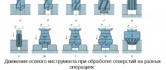
Movements in the machine
- Cutting movement - rotation of the spindle with the cutting tool
- Feed movement - axial movement of the spindle with the cutting tool
- Auxiliary movements are manual movements of the table and spindle head in the vertical direction and rapid manual movement of the spindle along its axis.
Cutting movement. Spindle V (Fig. 55, a) is driven by an electric motor with a power of 4.5 kat through a V-belt drive 140-178 and a gearbox.
On shaft I of the gearbox there is a triple movable block of gears B1, which provides shaft II with three rotation speeds. From shaft II, through gears 34-48, rotation is transmitted to shaft III, on which a triple movable gear block B2 is located, driving hollow shaft IV, connected by a spline to spindle V. As can be seen from the graph (Fig. 55, b), spindle V has nine rotation speeds. The highest number of spindle revolutions nmax, taking into account the elastic sliding of the belt, is determined from the expression = 1070 rpm.
Feeding movement. The feed movement is borrowed from spindle V. The movement is transmitted through gears 27-50 and 27-50, feed box with sliding keys, safety clutch M1, shaft IX, worm gear 1-47. gear coupling M2, shaft X and rack and pinion transmission to the spindle sleeve.
The feed box contains three- and four-stage mechanisms with sliding keys.
From shaft VI, three rotation speeds are transmitted to shaft VII, on which gears 60, 56, 51, 35 and 21 are rigidly fixed. From shaft VII, four rotation speeds are transmitted to shaft VIII.
Theoretically, the feedbox provides 12 rotation speeds, however, as can be seen from the graph (Fig. 54), one of them is repeated, so the 2A135 machine has only 11 different feed rates.
From shaft VIII, through the jaw clutch M1, movement is transmitted to shaft IX, on which the worm is fixed. The worm wheel is located on the same shaft with rack and pinion gear 14, which is in mesh with a rack cut on the spindle sleeve. The M1 clutch is used to protect the feed mechanism from damage during overloads, as well as to automatically turn off the feed when working on stops.
The highest feed rate smax is determined from the expression 3.14*3.5*14 = 1.6 mm/rev.
Auxiliary movements. The spindle head is moved from handle P1 through a worm gear 1-32 and rack and pinion gear 18, which engages with a rack m=2 mm fixed to the frame.
Vertical movement of the table is achieved by turning handle P2 through shaft XI, bevel gears 16-43 and lead screw XII.
Rapid movement of the spindle with the sleeve is carried out by a handwheel Ш connected by a special lock to shaft X. The lock allows the handwheel to rotate freely on shaft X within 20°, and subsequently connects them into one whole.
Electrical equipment and electrical circuit of the drilling machine 2N135
Electrical diagram of drilling machine 2N135
Electrical diagram of a drilling machine 2N135. View enlarged
Description of the operation of the electrical circuit of the machine
By turning on the input circuit breaker B1, voltage is supplied to the main and auxiliary circuits, and the signal lamp lights up. If cooling and lighting are required, the corresponding switches are placed in the “ON” position. By pressing the Kn2 “RIGHT” button, the starter coil P1 receives power, the main contacts turn on M1 for right rotation of the spindle. Through the block contacts P1, the starter P5 is turned on, which turns on the electric pump M2 and the delay relay P12.
When you press the KnZ “LEFT” button, the starter P1, the electric motor M1, the relay P12 are turned off after the capacitor C3 is discharged, the contacts of the relay P12 (28-26) are closed and the starter P2 and M1 are turned on for left-hand rotation. Relay P12 turns on again.
With automatic reverse, these switches occur when microswitch B4 is triggered by a cam mounted on the dial.
Stopping is carried out by pressing the Kn1 “STOP” button, this turns off the starters P1 or P2, P5, turning off M1, M2. Through relay contacts P12 (7-9), relay P11 is switched on, followed by switching on starters P3 and P4. The windings of the electric motor M1 are connected through rectifiers D1, D2 to the transformer Tr2, and dynamic braking occurs. After the discharge of capacitor C1, C2, relay P11 is turned off, disconnecting starters P3, P4 and M1 from the brake circuit.
When switching speeds, if the gears do not engage, a stepwise rotation of the electric motor rotor is used. By pressing the Kn4 “CURVE” button, the starter P4 is turned on, and a reduced rectified voltage flows through phases 1C2-1C3. Through resistance P2, relay P11 is turned on with a delay, turning off starter P4 and turning on P3 - the voltage flows through phases 1C1-1C2. Such switchings provide swinging of the rotor and kinematics, which makes it easier to change speeds.
Thermal relays are used to protect against overload. For zero protection - coils and contacts of magnetic starters.
Information about the manufacturer of the vertical drilling machine 2Р135Ф2
The manufacturer of drilling machines models 2Р135Ф2, 2Р118Ф2, 2Н125, 2Н135, 2Н150, 2Г175 is the Sterlitamak Machine Tool Plant, founded in 1941.
The history of the Sterlitamak Machine Tool Plant begins on July 3, 1941, when the evacuation of the Odessa Machine Tool Plant to the city of Sterlitamak began.
Already on October 11, 1941, the Sterlitamak Machine Tool Plant began producing special modular machines for the defense industry.
Currently, the plant produces metalworking equipment, including drilling and honing machines, CNC lathes and milling machines, multifunctional machining centers, metalworking and cutting tools.
Products of the Sterlitamak Machine Tool Plant
- 2135
— universal vertical drilling machine Ø 35 - 2A125
- universal vertical drilling machine Ø 25 - 2A135
- universal vertical drilling machine Ø 35 - 2A150
- universal vertical drilling machine Ø 50 - 2G175
- universal vertical drilling machine Ø 75 - 2N125
- universal vertical drilling machine Ø 25 - 2N135
- universal vertical drilling machine Ø 35 - 2N150
- universal vertical drilling machine Ø 50 - 2R135F2
- CNC vertical drilling machine Ø 35 - 2S125, 2S125-1 (2S125-01), 2S125-04
- universal vertical drilling machine Ø 25 - 2S132, 2S132K
- universal vertical drilling machine Ø 32 - 2С150ПМФ4
- vertical drilling-milling-boring machine with CNC and ASI 500 x 1000 - 400V
- vertical drilling-milling-boring machine with CNC and ASI 400 x 900 - SF-16, SF-16-02, SF-16-05
- tabletop milling and drilling machine Ø 16
Drilling tool
To secure cutting tools (drills, reamers, countersinks, taps), special chucks and intermediate devices are used, and if the dimensions of the tool allow, they are installed directly into the spindle.
The mounting holes of machine spindles are standardized. As a rule, they have a conical shape (Morse taper).
If the cone of the cutting tool shank has a different cone from the cone of the spindle of a vertical drilling machine, then adapter bushings are used. For example, a drill is attached to a sleeve, and the sleeve is mounted in a spindle seat. If it is necessary to secure a cylindrical drill, then split bushings are used: they have a cylindrical hole on the inside and a conical hole on the outside.
Drill chucks are more universal because... It is easier and faster to secure a cutting tool in them, and if they are quick-clamping, this also reduces time.
Operating principle
Operation of the machine in operating mode occurs according to the following principle. The workpiece to be processed must be installed and securely fixed on the working surface of the coordinate table. The spindle with the installed tool should be located in the lowest position. Using the worktable longitudinal displacement system, the spindle must be centered.
Then you need to make sure that the end of the part to be processed and the spindle are coaxially positioned. Based on the kinematic possibilities, in the high-speed gearbox we select the rotation speed suitable for processing. We turn on the vertical electric motor of the main drive.
After setting up the kinematic diagram, the tool head moves to the end of the workpiece, and the desired technological operation is performed.
Types
Vertical drilling machines are divided into several types according to their layout:
- manual tabletop - installed on tables, workbenches, feeding is carried out by moving the handle manually;
- with a spindle assembly on a column - installed on a foundation pad, have a gearbox, long changeover time;
- with permanent spindles;
- with adjustable spindles.
Tabletop manual machines Column machines With fixed spindles With adjustable spindles
2A135 Universal vertical drilling machine. Purpose and scope
The 2A135 vertical drilling machine replaced an outdated machine in mass production 2135
.
The new model provides more convenient control of the feed and feed box. Improved ergonomics. The 2A135 machine was replaced by a more advanced model 2N135.
The universal vertical drilling machine, model 2A135, is designed for work in repair and tool shops, as well as in production shops with small-scale production; a machine equipped with accessories can be used in mass production.
Vertical drilling machine 2a135, with a nominal drilling diameter of 35 mm, is used in enterprises with single and small-scale production and is designed to perform the following operations: drilling, reaming, countersinking, countersinking, reaming, threading and trimming ends with knives.
Allows processing of parts in a wide range of sizes from various materials using tools from high-carbon and high-speed steels and hard alloys.
Drilling operations on machine 2a135
Design features of the drilling machine 2A135
The presence on the machine of a nine-speed gearbox with a control range of 68-100-140-195-175-400-530-750-1100 rpm, an 11-speed feed box with a control range of 0.115 to 1.6 mm per revolution and electric reverse provides selection of standard cutting modes for hole diameters up to 35 mm when drilling, reaming, countersinking, countersinking, reaming, threading, and also allows the use of cutting tools equipped with carbide.
The presence of mechanical spindle feed on machines, with manual control of work cycles.
Allows processing of parts in a wide range of sizes from various materials using tools from high-carbon and high-speed steels and hard alloys.
The machines are equipped with a device for reversing the main motion electric motor, which allows them to cut threads using machine taps while manually feeding the spindle.
The machine has high rigidity, strength of working mechanisms, drive power and a wide range of cutting speeds and feeds, allowing the use of cutting tools equipped with carbide. The presence of an electric reverse, controlled both automatically and manually, provides the ability to cut threads with manual approach and withdrawal of the tap.
The design of the vertical drilling machine model 2A135 provides for automatic switching on of the feed movement after the cutting tool is quickly brought to the workpiece and automatic switching off of the feed when the specified drilling depth is reached.
The specified drilling depth for blind holes is ensured by a special stopping mechanism with a stop. This mechanism is also a safety device that protects the feed mechanism from damage due to overload.
The machine spindle is mounted on precision rolling bearings. The lower support consists of a radial ball bearing of class AB. The upper support has one class B ball bearing.
The plant provides the possibility of changing the drive pulleys of the belt drive, which allows you to set the limits of the spindle speed in accordance with the technological tasks.
To reduce auxiliary time on the machine model 2A135, it is possible to turn the feed on and off using the same steering wheel that manually moves the spindle quickly.
Placement category 4 according to GOST 15150-69.
Functionality and scope of application
The 2n135 vertical drilling machine was developed by engineers from the Odessa Design Bureau of Industrial Installations.
During the Soviet era, this unit, assembled at the Sterlitamak Machine Tool Plant, was considered the most technologically advanced and reliable equipment for small industry and individual production.
The technical characteristics of this device allow it to perform such functional operations as drilling, reaming, countersinking, countersinking and threading. The 2N135 machine allows the operator to accurately select the drill feed mode and the number of revolutions, which allows the device to be optimally adjusted to work with any materials.
The power of the power unit, which, as the passport shows, is 4 kW, allows the 2n135 machine to effectively cope even with parts made of carbide steel with a high carbon content.
The wide popularity of this equipment in small-scale industrial and household use has led to the emergence of a large number of different modifications. Let's consider the main ones:
Operating machines 2N135
- 2N135K – vertical drilling machine of coordinate type, which is equipped with a cross working surface;
- 2E135A – drilling machine equipped with an automatic spindle feed system. The machine operator controls the equipment using push-button controls;
- 2N135-1 - this machine differs from the original model only in the presence of a round rotary table, which is capable of rotating around the supporting column;
- 2N135N – vertical drilling machine of a multi-position type, the operator has the ability to freely move the functional elements of the device around the axis of the supporting column;
- 2N135-S - the device passport says that this unit is similar to the base model in everything, with the exception of the flanged quill. This modernization makes it possible to install the working head on several spindles simultaneously;
- 2N135F2 – drilling machine equipped with CNC (computer numerical control). The most modern modification 2N135, which is also equipped with a turret and a cross working surface.
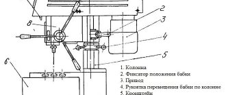
Design features
The supporting column of the unit is made in the form of a monolithic cast iron structure. Adjustment of the position of the worktable along the supporting column is performed manually by the operator by pressing the fixing element and turning the adjusting steering wheel. To move the working surface on the column, special guides are provided.
The base plate is also made of cast iron. The plate has a hollow shape, inside of which there is a reservoir for storing coolant, a filter device and a sedimentation tank for mechanical contaminants.
A 120-watt electric pump, which is located on the surface of the support column, is responsible for supplying coolant. The fluid is supplied through a system of tubes that supply water directly to the drill.
Structural diagram of the machine 2N135
The power unit of the 2N135 vertical drilling machine is located on top of the main body, which houses the gearbox and spindle unit. The kinematic diagram of the 2N135 machine is quite simple: the gearbox and power unit are connected via a straight shaft.
The gearbox itself is capable of delivering twelve spindle speeds. Speed adjustment is done manually by adjusting the tension belts. The handle for mechanical speed adjustment is located on the front part of the drilling head.
There is also an oil sensor on the front panel. Lubrication of the functional elements of the unit is carried out automatically using a plunger pump; the operator only needs to monitor the presence of the required amount of oil using the sensor.
The 2N135 vertical drilling machine is equipped with a manual spindle feed system. This system consists of an adjusting steering wheel, a worm gear, a cam and overrunning-ratchet clutch, a dial, and a horizontal shaft with a rack and pinion gear.
data-ad-client=»ca-pub-8514915293567855″ data-ad-slot=»5929285318″>