The dream of finding treasure is increasingly being replaced in our time by a more realistic program of searching for precious metals in a natural or artificial environment.
In modern conditions, it is very important to find and extract valuable materials found among waste , garbage or other uncontrolled environments.
Equipment is an important component of such search technology.
The search and extraction of gold and valuable metals from waste, garbage, in the natural environment is part of the recycling strategy, a technology for the effective processing of used materials, including the processing of precious metals.
Searching for them in the ground or in masses of industrial and other waste not only requires the use of equipment, but also stimulates its improvement. Devices of different levels and specializations are being created . There is interest in such equipment among amateurs and enthusiasts of searching for valuable metals.
Metal detector N. Martynyuk
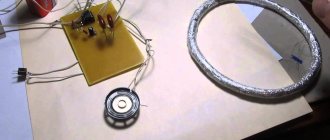
The metal detector according to N. Martynyuk’s scheme (Fig. 1) is made on the basis of a miniature radio transmitter, the radiation of which is modulated by an audio signal [Рл 8/97-30]. The modulator is a low-frequency generator made according to the well-known symmetrical multivibrator circuit.
The signal from the collector of one of the multivibrator transistors is fed to the base of the high-frequency generator transistor (VT3). The operating frequency of the generator is located in the frequency range of the VHF-FM broadcast range (64... 108 MHz). A piece of television cable in the form of a coil with a diameter of 15...25 cm was used as the inductor of the oscillating circuit.
Rice. 1. Schematic diagram of N. Martynyuk’s metal detector.
If a metal object is brought closer to the inductor of the oscillating circuit, the generation frequency will noticeably change. The closer the object is brought to the coil, the greater the frequency shift will be. To record frequency changes, a conventional FM radio receiver is used, tuned to the frequency of the HF generator.
The receiver's automatic frequency control system should be disabled. If there is no metal object present, a loud beep is heard from the receiver's speaker.
If you bring a piece of metal to the inductor, the generation frequency will change and the volume of the signal will decrease. The disadvantage of the device is its reaction not only to metal, but also to any other conductive objects.
Metal detector device
A metal detector is the most important tool for manually searching for metals in a chaotic natural or artificial environment.
Using such a device, you can search not only for ferrous metals, but also for gold, silver, and other precious metals.
The design principle of any metal detector is based on electromagnetic effects .
Here's how typical metal detecting technology works:
- The device creates an electromagnetic field .
- A metal object , secretly located in a foreign environment, affects such a field when it falls into its sphere of influence .
- The device detects the impact of an object on the electromagnetic field and signals about it .
A large number of metal detector models operate precisely on this principle.
Technical differences in such equipment make it possible to obtain more complete information about the fact of detecting a metal object, for example:
- estimate the mass of the find;
- obtain data on the shape, size and configuration of an object;
- specify the location, including depth.
There is a lot of information on the Internet about metal detectors of varying complexity and design. There you can also brush up on the theory of the electromagnetic field you studied in school.
The simplest , most primitive metal detectors (usually homemade designs for searching for gold, silver and other metals by amateur enthusiasts) are assembled from ready-made devices and products that work using electromagnetic effects.
Many are familiar with the primitive, but quite workable circuit of a metal detector, in which an electromagnetic field creates a pulse element of a conventional calculator.
The reaction of the created field to detected metal objects is picked up by the simplest household radio receiver .
The signal about such a find is audible, quite distinct and understandable. More complex amateur and professional metal detecting devices retain the logical basis of the technology in the form of three components :
- electromagnetic field generator;
- sensor of changes in this field;
- equipment for assessing detected anomalies, signaling this.
Devices of different levels of complexity and functional potential can be divided into groups. The classification based on the professionalism and specialization of users is one of the generally accepted:
- amateur equipment, assembled by hand and used as a hobby tool or by beginners in metal detecting;
- semi-professional equipment necessary for enthusiastic amateurs and fanatics;
- professional metal detectors for those constantly working in this field;
- special devices for metal detectors in difficult conditions - at depth, under water, with the release of precious metals.
The prevalence of metal detecting equipment is such that many devices of this type can be purchased at gardening and country supply stores.
A device for searching and detecting metal is needed not only for recycling, but also for searching for artifacts and treasures. Numerous security systems, well- known frames - one of the versions of metal detecting technology. The settings of these frames are focused on searching for weapons and similar dangerous objects.
Coil
A very important component of metal detecting equipment is a coil or frame . This is most often a winding of a special configuration, the task of which is to form an electromagnetic field and capture its reaction to the detection of a metal body foreign to the search environment.
In most designs, the coil is placed on a long rod - a handle for moving it near the search zone.
For amateur production of reels, frames of the most popular types are sold. The easiest way to make such a purchase is in an online store.
Many hobbyists
make their own reel frames .
This is done for reasons of cost savings or in the hope of obtaining a better-quality instrument of the author's design. For this, improvised means are used - plastic products, plywood, and even filling the assembled winding with construction foam.
The search operator or treasure hunter strives to find the most effective technique for working with a metal detector, choosing the desired operating modes of the electronics and the correct techniques for manipulating the coil.
Electronic circuit
The logical element of a metal detector is an electronic circuit. It performs many functions :
- The first task of this component is to create an electromagnetic signal of the desired format , which is converted into a field using a coil.
- The second task of the electronic circuit is to analyze field changes captured by the frame and process them.
- The third task is to provide an informing signal to the operator - sound, light, indicator readings and instruments.
It is best if anyone who wants to assemble an electronic circuit has knowledge of amateur radio or electronic technology. Such a master can not only assemble the required circuit, but also change and improve the design.
Many electronic devices are simple enough that even a beginner can assemble them . The resulting device will be operational without configuration if the assembler exactly followed the recommendations of the developer of such a circuit.
Metal detector based on a low-frequency LC generator
In Fig. 2 - 4 shows a circuit of a metal detector with a different operating principle, based on the use of a low-frequency LC oscillator and a bridge frequency change indicator. The search coil of the metal detector is made in accordance with Fig. 2, 3 (with correction of the number of turns).
Rice. 2. Metal detector search coil.
Rice. 3. Metal detector search coil.
The output signal from the generator is fed to a bridge measuring circuit. A high-resistance telephone capsule TON-1 or TON-2 is used as a bridge null indicator, which can be replaced with a pointer or other external alternating current measuring device. The generator operates at frequency f1, for example, 800 Hz.
Before starting work, the bridge is balanced to zero by adjusting the capacitor C* of the oscillating circuit of the search coil. The frequency f2=f1 at which the bridge will be balanced can be determined from the expression:
Initially, there is no sound in the telephone capsule. When a metal object is introduced into the field of the search coil L1, the generation frequency f1 will change, the bridge will become unbalanced, and a sound signal will be heard in the telephone capsule.
Rice. 4. Diagram of a metal detector with an operating principle based on the use of a low-frequency LC generator.
Pirate
Another popular pulse model for beginner treasure hunters is the “Pirate” metal detector. It is also easy to make with your own hands, detailed instructions in two versions:
- On the same NE555 chip. This is a classic generator that starts working when metal appears in the coil’s coverage area. No adjustments are required, just a squeak will be heard in the speaker.
- A metal detector assembled with transistors works on the same principle. Actually, the circuit is similar, only NE555 is replaced by a transistor generator with KT315.
It is advisable to bring the power supply closer to 12 volts, since the quality of operation depends on the voltage. Printed circuit boards have already been tested, both options are shown in the illustration.
The coil (in this case one) is made from the same 0.5 mm transformer wire. The optimal diameter is 20 mm, the number of turns is 25. Since we are making the “Pirate” metal detector with our own hands, the external design fades into the background. Any materials that you were ready to throw away will do.
It is better to make the handle detachable for ease of transportation. We remember that the use of metals is unacceptable.
Sensitivity is adjusted by two variable resistors in real time while searching. No fine tuning of the generator is required.
And if you manage to properly seal the case, you can start searching for “treasures” in the beach surf, and even at the bottom of the reservoir.
It is more difficult to make an underwater metal detector with your own hands, but it will give you an undeniable advantage over your competitors.
Improved performance
You can make a deep metal detector with your own hands from a ready-made “Pirate” without additional costs. There are two ways to do this:
- Increasing the diameter of the inductor. At the same time, downward permeability increases significantly, but sensitivity to small objects decreases.
- Reducing the number of coil turns while simultaneously adjusting the circuit. To do this, you will have to sacrifice one coil for experiments. We remove (and cut off) turn after turn until we see that the sensitivity begins to decrease. We remember the number of turns at maximum parameters, and make a new coil for this circuit. Then we change the resistor R7 to a variable one, with similar power parameters. After conducting several experiments with sensitivity, we fix the resistance and change the variable to a constant resistor.
The Pirate metal detector can be assembled using the popular Arduino controller.
It is more convenient to use such a device, but there will still be no metal discrimination.
Having figured out how to make a metal detector with your own hands for amateur tasks, we will briefly examine several serious models.
Metal detector bridge circuit
The bridge circuit of a metal detector using a search coil that changes its inductance when metal objects approach is shown in Fig. 5. An audio frequency signal from a low-frequency generator is supplied to the bridge. Using potentiometer R1, the bridge is balanced for the absence of an audio signal in the telephone capsule.
Rice. 5. Bridge circuit of a metal detector.
To increase the sensitivity of the circuit and increase the amplitude of the bridge unbalance signal, a low-frequency amplifier can be connected to its diagonal. The inductance of the L2 coil should be comparable to the inductance of the L1 search coil.
Advantages and disadvantages
Only a true connoisseur of antiquities can assemble a metal detector on his own. Such homemade devices have their advantages and disadvantages. The disadvantages are the following:
- Very low sensitivity.
- Low penetrating ability.
- Low quality of materials used.
- Large error in calculations.
Real metal detectors are manufactured taking into account many parameters. Their circuits take into account the laws of physics, for example, the effect of a magnetic field on metals of different chemical compositions. The diameters of the coils, the wire used, and the parameters of the main radio components are also taken into account. It is very difficult to independently calculate all these parameters.
Homemade devices for searching for precious metals are also not without advantages. The following can be highlighted:
- Independent work on the project. The beginner gains experience in designing and further setting up the device.
- Gaining experience in detecting various metal objects. A beginner can independently learn to determine the metal and its depth.
- Experience in determining search locations will be useful for subsequent improvement of search technology.
Such devices can be upgraded by adding more sensitive coils and powerful frequency generators.
Metal detector based on a receiver with the CB range
A metal detector operating in conjunction with a mid-wave superheterodyne radio broadcast receiver can be assembled according to the circuit shown in Fig. 6 [R 10/69-48]. The design shown in Fig. 1 can be used as a search coil. 2.
Rice. 6. A metal detector operating in conjunction with a superheterodyne radio receiver in the CB range.
The device is a conventional high-frequency generator operating at 465 kHz (the intermediate frequency of any AM broadcast receiver). The circuits presented in Chapter 12 can be used as a generator.
In the initial state, the frequency of the HF generator, mixing in a nearby radio receiver with the intermediate frequency of the signal received by the receiver, leads to the formation of a difference frequency signal in the audio range. When the generation frequency changes (if there is metal in the field of action of the search coil), the tone of the sound signal changes in proportion to the amount (volume) of the metal object, its distance, and the nature of the metal (some metals increase the generation frequency, others, on the contrary, lower it).
Simple metal detectors from ready-made electrical appliances
A metal detector can be easily built from a radio receiver and equipped with a high-frequency transmitter. The coil consists of 16 turns with a diameter of 12 cm, wire cross-section 0.5 mm². When metal is detected, the signal height changes.
A homemade metal detector made according to a circuit diagram can be no less reliable than a factory-made device. The simplest metal detector can be made without specialized equipment, even without having any experience in working with radio electronics.
A simple metal detector with two transistors
Rice. 7. Scheme of a simple metal detector using silicon and field-effect transistors.
The diagram of a simple metal detector is shown in Fig. 7. The device uses a low-frequency LC generator, the frequency of which depends on the inductance of the search coil L1. In the presence of a metal object, the generation frequency changes, which can be heard using the BF1 telephone capsule. The sensitivity of such a scheme is low, because It is quite difficult to detect small changes in frequency by ear.
Homemade metal detector - pros and cons
Cheapness , the basic advantage of making any products yourself, is relevant for a metal detector. Here are some other advantages of a homemade device:
- best match to search technology for beginners;
- the ability to create a device with a completely individual shape, design and configuration;
- the pleasure of making an effective, efficient device yourself.
Like any device made by an amateur, a metal detector is not without some drawbacks .
Here are the features of the “Pirate” model that users note:
- battery consumption
- lack of discrimination , that is, precise sensitivity to ferrous, non-ferrous and precious metals;
- limited sensitivity compared to expensive models .
Despite its shortcomings, the Pirate model is very popular. This is explained by the simplicity of homemade production and the high performance of an inexpensive device.
Recycling experts believe that the discrimination capabilities of a metal detector are not of great importance. All metals found are so valuable that recycling them is always justified. Focusing on finding gold requires not only equipment, but also considerable experience , related knowledge and, of course, luck .
Metal indicator circuit
A different method of indicating the presence of metal is used in the device according to the diagram in Fig. 9. The device contains a high-frequency generator with a search coil and operates at frequency f1. To indicate the signal magnitude, a simple high-frequency millivoltmeter is used.
Rice. 9. Schematic diagram of a metal indicator.
It is made on diode VD1, transistor VT1, capacitor C1 and milliammeter (microammeter) PA1. A quartz resonator is connected between the output of the generator and the input of the high-frequency millivoltmeter. If the generation frequency f1 and the frequency of the quartz resonator f2 coincide, the needle of the device will be at zero. As soon as the generation frequency changes as a result of introducing a metal object into the field of the search coil, the needle of the device will deviate.
The operating frequencies of such metal detectors are usually in the range of 0.1...2 MHz. To initially set the generation frequency of this and other devices of similar purpose, a variable capacitor or a tuning capacitor connected in parallel with the search coil is used.
Self-production
Beginners who decide to try their hand at searching for precious metals should understand that a homemade device will not have the sensitivity and penetration depth of professional metal detectors. Self-assembled devices will help identify precious metals at a depth of approximately 1 meter. It will also be possible to determine silver and gold containing objects on the soil surface. Next, we will present 2 instructions for assembling a metal detector for gold, which you can assemble with your own hands.
Device 1
This device is the simplest. Its assembly does not require a beginner to have deep knowledge of electronics and electrical engineering. The device will be quite simple and primitive, but will be able to detect gold and silver at a depth of up to 0.5 meters in loose soils. For example, with its help it will be possible to search for gold jewelry lost on the beach. For assembly you will need:
- An ordinary radio receiver. The device must be powered by batteries with a voltage of at least 9 volts.
- Electronic calculator.
- Plastic box, you can use DVD packaging.
- Several screws for fastening or double-sided tape.
- Wooden stick.
For this simple circuit you will need the cheapest receiver and calculator. The calculator is equipped with a clock generator. This electronic device has a high potential for causing interference to radio waves.
So, the instructions for assembling the device are as follows:
- The disc box must be opened.
- Attach the radio receiver to its cover. You can use tape or attach the device with screws. The main thing is not to damage the internal elements. It is worth remembering that the receiver, even the smallest one, is a fairly heavy device. The further operation of the homemade metal detector depends on its fastening.
- In the same way, the calculator is attached to the second, inner side of the box.
- The “AM” band is selected on the receiver. In this case, you need to choose an almost empty frequency with a minimum amount of interference and noise on the air.
- Set the receiver sound to maximum.
- Next you need to turn on the calculator. The receiver will respond to clock generator interference with a crackling sound or noise from the speaker. If there is no noise, then you need to bring the calculator as close as possible to the receiver.
- Now it is necessary to reduce the influence of the generator on the receiver. This is done using the lid of the box. Both devices attached to the lid must be brought as close to each other as possible. After reducing the impact of interference, the position of the box covers and devices on it must be fixed. You can install a wooden spacer or twist the whole structure together using insulating tape.
- The entire structure is attached to the end of a long stick. This is done for ease of finding and carrying.
After manufacturing and setting up a “homemade product”, it needs to be tested. To do this, you need to take an object made of gold and place it on the sand. Next, hold a homemade device over the location of the object. The receiver should react with the appearance of noise on the air. After detection, you need to test the device’s ability to search at different depths. It is also worth experimenting with metals of different composition and volume to more accurately determine precious and ferrous elements in the soil. The range of penetration increase is adjusted by positioning the calculator relative to the receiver. Such a homemade product is not capable of detecting gold at a depth of 1 meter. But with its help, you can learn to identify metal objects by noise in the air, and become infected with the desire to construct a more sensitive and powerful device.
Device 2
To create this device, knowledge of electrical engineering, ability to work with a soldering iron and reading electronic circuits will be useful. The assembled device belongs to simple pulse-frequency devices. It has higher penetrating power and the ability to adjust the vibration frequency level. This device consists of the following elements:
- The main generator for searching. This device works with a transmitter coil. The main purpose of the element is to transfer the created MP directly into the soil.
- Auxiliary generator. Necessary to increase the magnetic field. It also increases the depth of signal transmission and the scanning area. In the circuit of this part there is a substring resistor, with which you can adjust the power and the size of the impact zone.
- Receiver. The main part of the device is used to receive a return signal from scanned objects.
- Frequency filter. Will help reduce radio interference from running generators. Its function also includes smoothing out external noise.
- Electronic amplifier. It is necessary to receive the final signal using an external speaker or headphones. Instead of headphones or a speaker, you can use light indicators based on LEDs. As an option, supplement the existing diagram with these elements. This will allow you to identify a find when working in particularly noisy areas due to an additional option - light indication.
- Stabilizer. This device will help equalize the power current from a portable battery or battery.
- Variable resistors. Their main function is to adjust the sound volume and tone of the outgoing signal.
Next, you need to assemble all the components of the circuit together.
Printed circuit board
It is very important to create this element on a PCB plate. This will help firmly secure the radio components and avoid burning through the base during soldering. The circuit diagram presented below must be printed on a printer. Next, you need to transfer the design onto copper foil and carefully cut it out. The resulting scheme is superimposed on a textolite base. At the final stage, the workpiece is processed with a hot iron. Thus, the copper part is fused into the surface of the textolite. At the junctions of radio components, it is necessary to make holes using a thin drill or awl.
Very important! During circuit assembly, work with a soldering iron is carried out without long delays at the soldering points. This will help protect radio components from overheating and damage.
Next, you need to assemble a circuit diagram of the metal detector, strictly observing the order in which all its components are connected.
Coil
This part of the metal detector is in constant contact with the soil. It can be easily damaged by stones, branches and other terrain elements. In order to protect the coil, it is better to assemble it from pieces of thick plywood. The thickness of the plywood must be at least 5 mm. Before designing a coil, it is necessary to determine its diameter. This is a very important point. The optimal diameter for detecting gold objects and small nuggets is from 130 to 150 mm. The part is assembled as follows:
- 2 circles with a diameter of up to 200 mm are cut from plywood. every
- Next, another circle with a diameter of 125 to 160 mm is cut out.
- A small diameter part is placed on a large diameter circle. The entire structure is fixed with screws.
- At a distance of 2–3 cm from the center of the workpiece, a hole with a diameter of 5–10 cm is drilled. A hole must also be made in the central circle.
- Next, you will need a varnish-insulated copper wire with a cross-section of up to 0.3 mm. It needs to be wound around a central circle of plywood. The number of turns must be at least 80.
- Both ends of the coil wire lead out into the central hole. The length of the ends must be at least 300 mm. This will make it much more convenient to connect the wire to the block. The ends are pulled out at the very end of the assembly.
Next, you need to disassemble several electrolytic capacitors. They have aluminum foil inside. You need to take it out and wash it thoroughly. Further:
- Remove the wound wire from the small plywood circle.
- Fasten the coil in several places with thin insulated wire. For example, a telephone cable is suitable for this. You can use insulating tape.
- Very tightly in one layer, wrap the workpiece with foil from the capacitors. It is very important that the ends of the previously wound wire are at a distance of 10 cm from each other. In addition, it is necessary that the ends of the wires protrude from under the foil.
- The foil is secured at the ends with insulating tape.
- Now you need a wire with a cross section of 0.5 mm. You can take a regular wire without varnish insulation, or first remove it using sandpaper.
- The prepared wire along its entire length must be tinned using a soldering iron and tin. It is very important to maintain a thin layer of tin on the surface of the wire when working.
- The end of the prepared wire is connected to the end of the coil.
- Next, the wire is wrapped over the foil. It is necessary to strictly maintain a step of 1 centimeter.
- The second end of the wire is attached to the coil using insulating tape.
- The entire resulting structure must be tightly wrapped with insulating tape.
- Place again on the center plywood circle.
- Lead the ends of the wires into the central hole.
- Place a third plywood circle on top of the structure and fasten it all with screws.
Next you will need to assemble the entire structure.
Assembly
In order to collect all the prepared parts, you need a plastic container with a well-closing lid and a wooden stick. A cutting from a medium-diameter garden tool works very well.
- The assembled board with battery is placed in the container.
- The container is attached to the cutting at a distance of 20–30 cm from the upper end.
- The inductor coil frame is attached to the second end of the handle.
- The end of the wire, which is the beginning of the coil, is secured to the handle with a screw.
- The second, paired end from the coil is connected using a long, insulated wire to pin “1” of the C1.1 chip, indicated on the circuit diagram.
- The third end of the coil is connected to the terminal of capacitor C1.
Both wires can be wrapped around the holder, or run along it, secured with insulating tape. Next, the resulting device is configured.
Settings
Before testing the device, it is necessary to make preliminary settings of the assembled circuit. This will help identify faults and conduct a frequency oscillation test. The parameters are configured as follows:
- Initially, the frequency and volume of the received signal are adjusted. To do this, you need to turn on the power of the metal detector, and by rotating the substring resistor R5, find the position with the loudest and most frequent signal. The found position is fixed.
- Next you will need a gold item. You need to bring the device coil to it. A low frequency signal should appear. By rotating resistor R4 it is necessary to achieve the highest sounding signal. The position of the element also needs to be fixed.
- Using resistor R2, the intensity of the received signals is adjusted. It is necessary to move the coil to a distance of up to 0.5 cm and listen to the frequency sound. Try to strengthen it. If there is no gain, then you need to move the coil 10 centimeters closer and repeat the adjustment. In this way, the greatest depth and clarity of the signal is selected.
Next, the device is tested directly on the ground. An object made of precious metal is placed on the surface of the soil and searched for. Once the product has been detected, it must be placed to a depth of no more than 10 centimeters and the test repeated. With each new test, the item is placed at greater depth. To expand the search and configure the device, you need to repeat the test with a product made of silver and “ferrous” metal. This way, a beginner will be able to evaluate the received signal from different metals at different depths.
During testing and further operation of the assembled device, you need to remember that the frequency and level of frequency vibrations directly depends on the composition of the soil, its hardness, humidity, size of the object, and so on.
Typical metal detector with two generators
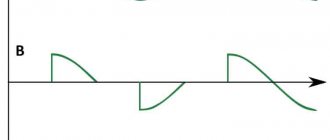
In Fig. Figure 10 shows a typical diagram of the most common metal detector. Its operating principle is based on the frequency beats of the reference and search oscillators.
Rice. 10. Diagram of a metal detector with two generators.
Rice. 11. Schematic diagram of the generator block for a metal detector.
A similar node, common to both generators, is shown in Fig. 11. The generator is made according to the well-known “three-point capacitive” scheme. In Fig. Figure 10 shows a complete diagram of the device. The design shown in Fig. 1 is used as search coil L1. 2 and 3.
The initial frequencies of the generators must be the same. The output signals from the generators through capacitors C2, SZ (Fig. 10) are fed to a mixer that selects the difference frequency. The selected audio signal is fed through the amplifier stage on transistor VT1 to the telephone capsule BF1.
DIY metal detector Clone PI W
In essence, this is a cheaper version of the professional finder Clone PI-AVR, only instead of an LCD display, a line of LEDs is used. This is not as convenient, but still allows you to control the depth of artifacts.
The best option for the price is the CD4066 chip and ATmega8 microcontroller.
Of course, there is also a printed circuit board layout for this solution, only the control buttons are placed on a separate panel.
Programming ATmega8 is a topic for a separate article; if you have worked with such controllers, no difficulties will arise.
The powerful Clone PI W metal detector, made by yourself, allows you to find metal no more than a meter deep, although without discrimination.
Metal detector based on the principle of generation frequency interruption
The metal detector can also operate on the principle of disrupting the generation frequency. The diagram of such a device is shown in Fig. 12. If certain conditions are met (the frequency of the quartz resonator is equal to the resonant frequency of the oscillatory LC circuit with the search coil), the current in the emitter circuit of transistor VT1 is minimal.
If the resonant frequency of the LC circuit changes noticeably, the generation will fail, and the readings of the device will increase significantly. It is recommended to connect a capacitor with a capacity of 1 ... 100 nF in parallel to the measuring device.
Rice. 12. Circuit diagram of a metal detector that works on the principle of disrupting the generation frequency.
Main settings
Like any technical device, a metal detector has certain parameters that characterize its functional properties.
Detection depth
In the first place is the depth of metal detection. By the way, many companies producing such devices do not indicate the maximum depth at which their products can detect metal products. And if such a figure is indicated, then most likely this is data obtained during laboratory tests. That is, real field conditions differ significantly from laboratory (test) conditions.
This means that when doing real work with your own hands, the detection depth will be slightly less than indicated in the passport. Why is this happening? The fact is that the composition of the soil has a significant impact on the capabilities of the metal detector. In fact, it is one thing to search in river sand, and another in soil with a high iron content. Metal products, especially those that remain at depth for a long time, oxidize and change their properties, and this affects the ability to detect an object.
Metal detector detection depth
Most modern metal detectors can find metal objects at a depth of up to 2.5 m; special deep products can detect a product at a depth of up to 6 meters.
Operating frequency
The second parameter is the operating frequency. The thing is that low frequencies allow the metal detector to see to a fairly large depth, but they are not able to see small details. High frequencies allow you to notice small objects, but do not allow you to view the ground to great depths.
The simplest (budget) models operate at one frequency; models that fall into the middle price range use 2 or more frequencies. There are models that use 28 frequencies when searching.
Metal detectors for searching for small objects
Metal detectors, designed to search for small metal objects in everyday life, can be assembled according to those shown in Fig. 13 - 15 schemes.
Such metal detectors also operate on the principle of generation failure: the generator, which includes a search coil, operates in a “critical” mode.
The operating mode of the generator is set by adjusted elements (potentiometers) so that the slightest change in its operating conditions, for example, a change in the inductance of the search coil, will lead to disruption of the oscillations. To indicate the presence/absence of generation, LED indicators of the level (presence) of alternating voltage are used.
Inductors L1 and L2 in the circuit in Fig. 13 contain, respectively, 50 and 80 turns of wire with a diameter of 0.7...0.75 mm [Fs 8/75]. The coils are wound on a 600NN ferrite core with a diameter of 10 mm and a length of 100... 140 mm. The operating frequency of the generator is about 150 kHz.
Rice. 13. Circuit of a simple metal detector with three transistors.
Rice. 14. Scheme of a simple metal detector using four transistors with light indication.
Inductors L1 and L2 of another circuit (Fig. 14), made in accordance with the German patent (No. 2027408, 1974), have 120 and 45 turns, respectively, with a wire diameter of 0.3 mm [P 7/80-61 ]. A 400NN or 600NN ferrite core with a diameter of 8 mm and a length of 120 mm was used.
Design and principle of operation of the device
Metal detectors on the market operate on different principles. Many believe that they use the principle of pulse echo or radar. Their difference from locators lies in the fact that the transmitted and received signals act constantly and simultaneously; in addition, they operate at the same frequencies.
The principle of operation of the metal detector
Devices operating on the “receive-transmit” principle record the signal reflected (re-emitted) from a metal object. This signal appears due to the exposure of a metal object to an alternating magnetic field generated by the metal detector coils. That is, the design of devices of this type provides for the presence of two coils, the first is transmitting, the second is receiving.
Metal detector circuit
Devices of this class have the following advantages:
- simplicity of design;
- Great potential for detecting metallic materials.
At the same time, metal detectors of this class have certain disadvantages:
- metal detectors can be sensitive to the composition of the soil in which they search for metal objects.
- technological difficulties in the production of the product.
In other words, devices of this type must be configured with your own hands before work.
Other devices are sometimes called beat metal detectors. This name comes from the distant past, more precisely from the times when superheterodyne receivers were widely used. Beating is a phenomenon that becomes noticeable when two signals with similar frequencies and equal amplitudes are summed. The beat consists of pulsating the amplitude of the summed signal.
The signal pulsation frequency is equal to the difference in the frequencies of the summed signals. By passing such a signal through a rectifier, it is also called a detector, and the so-called difference frequency is isolated.
This scheme has been used for a long time, but nowadays it is not used. They were replaced by synchronous detectors, but the term remained in use.
A beat metal detector works using the following principle - it registers the difference in frequencies from two generator coils. One frequency is stable, the second contains an inductor.
The device is configured with your own hands so that the generated frequencies match or at least are close. As soon as metal enters the action zone, the set parameters change and the frequency changes. The frequency difference can be recorded in a variety of ways, from headphones to digital methods.
Devices of this class are characterized by a simple sensor design and low sensitivity to the mineral composition of the soil.
But besides this, when using them, it is necessary to take into account the fact that they have high energy consumption.
Typical design
The metal detector includes the following components:
- The coil is a box-type structure that houses the signal receiver and transmitter. Most often, the coil has an elliptical shape and polymers are used for its manufacture. A wire is connected to it connecting it to the control unit. This wire transmits the signal from the receiver to the control unit. The transmitter generates a signal when metal is detected, which is transmitted to the receiver. The coil is installed on the lower rod.
- The metal part on which the reel is fixed and its angle of inclination is adjusted is called the lower rod. Thanks to this solution, a more thorough examination of the surface occurs. There are models in which the lower part can adjust the height of the metal detector and provides a telescopic connection to the rod, which is called the middle one.
- The middle rod is the unit located between the lower and upper rods. Devices are attached to it that allow you to adjust the size of the device. On the market you can find models that consist of two rods.
- The top rod usually has a curved appearance. It resembles the letter S. This shape is considered optimal for attaching it to the hand. An armrest, a control unit and a handle are installed on it. The armrest and handle are made of polymer materials.
- The metal detector control unit is necessary to process the data received from the coil. After the signal is converted, it is sent to headphones or other display devices. In addition, the control unit is designed to regulate the operating mode of the device. The wire from the coil is connected using a quick release device.
Metal detector design
All devices included in the metal detector are waterproof.
It is this relative simplicity of design that allows you to make metal detectors with your own hands.
Household metal detector
A household metal detector (HIM) (Fig. 15), produced earlier (Moscow), allows you to detect small metal objects at a distance of up to 45 mm. The winding data of its inductors are unknown, however, when repeating the circuit, you can rely on the data given for devices of similar purposes (Fig. 13 and 14).
Rice. 15. Scheme of a household metal detector.
Literature: Shustov M.A. Practical circuit design (Book 1), 2003
DIY Terminator 3
If you need a homemade metal detector with metal discrimination, pay attention to this model. The scheme is quite complicated, but your efforts pay off with the coins you find, which may turn out to be gold.
The peculiarity of the “Terminator” is the separation of the receiving and transmitting coils. A 200 mm ring is made to emit the signal. 30 turns of wire are laid for it, then it is cut, as a result we get 2 half-coils with a total capacity of 60 turns (see diagram).
The receiving coil is located inside, 48 turns with a diameter of 100 mm.
The adjustment is made using an oscilloscope; after achieving optimal amplitude results, the windings are fixed in the housing by pouring epoxy resin.
Then an experimental hands-on adjustment of the discrimination switch is performed. For this, real objects made of various metals are used, and their type is marked on the mode switch (after verification).
Radio amateurs are working on an improved version of Terminator 4, but there is no practical copy yet.
How does a metal detector work?
A metal detector, or metal detector, is an electronic device consisting of a primary sensor (coil with winding) and a secondary unit. Metal detection devices are divided into several types:
- "reception and transmission";
- induction;
- pulse;
- generator
Metal detector device
Devices in the mid-price category are mainly of the “receive-transmit” type. The operating principle of such metal detectors is based on the transmission and reception of electromagnetic waves. The main elements of a device of this type are two coils: one is transmitting, and the second is receiving. The first coil transmits electromagnetic waves that freely pass through a neutral medium and which, when colliding with metal objects, are reflected and transmitted to the receiving device. After the reflected signal hits the second coil, the operator is informed by a buzzer that the target has been found.
The principle of operation of the metal detector
An induction-type metal detector operates on the same principle as transmit-receive devices. The main difference between them is the number of coils with winding. An induction metal detector has one coil that sends and receives a signal simultaneously. Pulse devices are insensitive to the concentration of salts in the soil and include in their design a coil, the electromagnetic field of which creates eddy currents on the metal surface that are captured by the detector. This principle of operation reduces the possibility of discrimination, which can complicate the search.
Operating principle of a pulse metal detector
Generator-type metal detectors come in different types, but they are all built on the basis of an LC generator. They have a low level of sensitivity and are generally designed to find only one type of metal. Metal detectors can also be divided into three
- common use;
- middle class;
- professional equipment.
Me and Diode. Entertaining - Tech Blog
After reading a little about amateur radio forums on making metal detectors , I discovered that most people who assemble metal detectors , in my opinion, unfairly write off beat-based metal detectors - the so-called BFO metal detectors . Allegedly, this is the technology of the last century and “children’s toys.” — Yes, this is a simple and unprofessional device that requires certain skills and experience in handling. It does not have a clear metal selectivity and requires adjustment during operation. However, it is also possible to perform a successful search under certain circumstances. As an option, beach searching is an ideal option for a beating metal detector .
Instructions for making a metal detector for gold
Parts and materials
The classic device consists of:
- Reels.
- Decoder.
- Signaling device.
A metal detector consists of a coil, a decoder and an alarm.
In addition, for the upcoming work you should prepare:
- Ceramic and electrical capacitors.
- Resonator.
- Controllers.
- Film capacitors.
- Stabilizer.
- Resistors.
- Sound emitters.
- Wires and insulating tape.
- Materials for preparing the barbell.
- Resistors.
- Chips K157UD2 and NE.
Scheme
The classic metal detector assembly diagram looks like this:
- Capacitors, resistors and transistors are fixed on the main board, taking into account the selected circuit.
- Next, 2 wires from the battery compartment and speakers are soldered.
- Then the wire is wound onto the frame. Having made 10 turns, you need to provide a 20-centimeter outlet.
- At the next stage, you will need to remove the coil from the frame and secure the turns with electrical tape.
- After this, a second coil is wound, which mirrors the previous one.
- Taking into account the circuit, you should solder the detector leads and assemble the stand, placing the coils at a distance of 15 cm. A board is installed between them.
- The elements are fixed with glue and covered with oily varnish.
- A handle is attached to the stand.
Electrical circuit of a metal detector.
Diagram of a metal detector made from a pen.
Metal detector coil diagram.
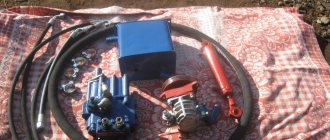
AKS metal detector equipment
The device consists of the following main elements:
- Main radar unit with LED indication
- Receiver with indication
- Charger adapter 220 V
- DVD with instructions
- Waterproof case
Next, watch the video, which shows practical work with the MD, as well as disassembling the case and the internal diagram. The quality is not very good, but we managed to see such a board with parts and a couple of microcircuits. The second smaller one is the charger unit.
A little about smartphones
There is an opinion that it is quite possible to make a metal detector from a smartphone. This is wrong! Yes, there are applications that install under Android OS.
But in fact, after installing such an application, he will actually be able to find metal objects, but only pre-magnetized ones. It will not be able to search for, much less discriminate against, metals.
If you find an error, please select a piece of text and press Ctrl+Enter.
Author Topic: DIY metal detector - the best ideas (Read 10112 times)
0 Users and 1 Guest are viewing this topic.
Quick response
You can use BB tags and emoticons in a quick reply.
Warning: There have been no posts in this thread for more than 30 days. If you are not sure what you want to answer, it is better to create a new topic.
Please note: This message will not appear until a moderator approves it.