A rotary pump is a device that is used in cases where it is necessary to pump various liquid media in large volumes. The various types of rotary pumps offered on the modern market differ in both design and technical characteristics, as well as in their operating principle. The variety of types of such pumping equipment determines its effective use in various fields.
High pressure rotary pumps are used in cooling systems, reverse osmosis and circulation of water or other liquids
Operating principle and types
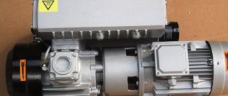
The principle on which rotary pumps operate is as follows. The pumped liquid first enters the internal chamber of the device, from which it is pushed out by rotational and translational movements performed by the working body - the rotor. The rotor parts, along with the inner walls of the working chamber, form a closed space into which the liquid enters. When the volume of such space decreases, which occurs when the rotor moves, the liquid is pushed out according to the laws of physics.
Operating principle of a rotary pump
Depending on the design of the working body, rotary (or rotary) pumps can belong to different categories. In addition, rotary pumps are divided into different types according to the type of movement performed by their working body. Based on this feature, rotary-rotational and rotary-translational devices are distinguished. The working body of rotary pumps of the first type, as is clear from their name, performs only rotational movements, and in installations of the second type this movement is combined - both rotational and translational.
Rotary-rotary pumps, depending on the design of the working body and the principle of operation, are divided into gear (toothed) and screw. In the first, the working chamber is formed by the inner walls of the housing and gears, which are made with both internal and external gearing. In this case, the working chamber changes due to the rotation of gears. The elements from which the working chamber of screw-type rotary pumps is formed are the internal walls of the housing and one or more screws. A screw rotating around its axis forms temporary working chambers inside the pump, which, together with the transported liquid, move along the axis of the screw to the discharge pipe.
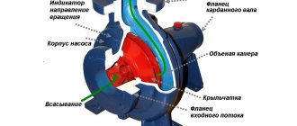
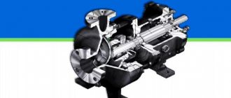
Diagram of a rotary vane pump
Progressive type rotary pumps are divided into vane or vane pumps and plunger pumps. In gate-type devices, the working body is a rotating rotor, into the longitudinal slots on the body of which special plates called gates are inserted. The rotor axis in such pumps is not identical to the axis of the cylindrical body in which it rotates. The working chamber of vane pumps is formed by two adjacent gates, the rotor itself and the inner walls of the housing. To ensure the tightness of the working chamber created in this way, the plates must be pressed tightly against the walls of the housing. This problem is solved either by centrifugal force pressing the working part of the plates against the walls of the housing, or by special spring-type devices. Vane-type rotary pumps can differ from each other in rotor design and be equipped with a different number of plates, depending on which they are divided into single-, double-shot devices, etc. actions.
Based on their operating principle and design, rotary plunger pumps are divided into axial and radial piston pumps. Their working bodies are plungers (pistons), which perform a simultaneous rotational and translational movement inside the device body. The difference between such rotary machines and conventional piston machines is that they can work both as pumps and as hydraulic motors, that is, they are reversible.
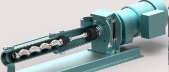
Diagram of a rotary plunger pump
Jabsco Gear Type Rotary Vacuum Pump
- Productivity - 1500 l/h
- Maximum pumping viscosity 150Cs
- Self-priming up to 1 meter
- Explosion protection (ISO 8846 MARINE)
- Complies with USCG 183.410
More details
Advantages and disadvantages
There are several of the most significant advantages of using rotary pumps:
- more uniform, when comparing rotary pumps with reciprocating type devices, the supply of liquid to the pipeline system (however, due to the design features of rotary equipment, it will not be possible to ensure a completely uniform supply);
- reversibility, that is, the possibility of using such devices both as a pump and as a hydraulic motor;
- absence of valves, which helps reduce power losses and, accordingly, increase efficiency;
- high performance due to operation at significantly higher speeds compared to piston-type devices.
The efficiency of the pumping process with a rotary lobe pump is ensured by adjusted tolerances between the housing and the rotors
If we talk about the disadvantages that a rotary pump has, the most significant of them include the following.
- High demands are placed on the medium pumped by such pumps, since it should not interfere with the tight fit of the moving working elements to the inner walls of the housing. In particular, the liquid pumped by rotary pumps must have minimal chemical aggressiveness and not contain abrasive inclusions.
- The rotary pump has a more complex design when compared with reciprocating type devices, which affects both its reliability and the cost of production and maintenance.
Jabsco Sliding Vane Rotary Vane Pump
- Housing - aluminum;
- Shaft - stainless steel;
- Productivity - 1500 l/h;
- Corrosion resistant IP44.
More details
Performance calculation
Q = hSna = 2eSna
Q – pump performance;
e – eccentricity, displacement relative to the axis of rotation of the shaft in the figures above was also designated as “e”;
L – stroke of the plunger in the cylinder, in the standard situation L=2*e;
S – plunger area;
a – number of plungers in the block;
n – block rotation speed;
Performance in adjustable pumps is regulated by changing the deviation of the “e” axis.
Piston pumps
From the name it is clear that the pistons act as a displacer. Under their action, hydraulic fluid moves in the pump and along all lines of the hydraulic system. These units come in three types.
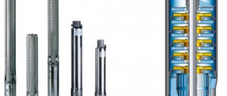
Manual
Hydraulic machines of a simple design, designed for pressures up to 15 MPa, less often - up to 50 MPa. Typically used as an additional or backup power source for hydraulic motors. Hand pumps come in single- and double-acting types.
Radial piston
A low-noise device for operation under pressures of more than 40 MPa, and some models operate stably at 100 MPa. There are two types of equipment in this group:
· With eccentric shaft
. The elements of the piston group are located in the stator. The shaft is equipped with a cam, which, when rotated, imparts movement to the pistons. During the active phase, the pistons are filled with oil through suction valves. The liquid medium is injected using injection valves at the moment the pistons enter the cylinders;
· With eccentric rotor
. The components of the piston group are concentrated in the rotor, during the rotation of which the piston is driven. The distribution of liquid occurs due to the spool, which acts as a partition. During rotation, the cylinders are alternately connected to the discharge and drain cavities.
Axial piston
They are hydraulic machines in which the cylinders are located axially, i.e. parallel, around an axis or at a slight angle relative to it. In addition to pistons, plungers can also perform a displacement function.
These are the most popular types of high-pressure hydraulic pumps, due to their following characteristics:
· High efficiency and power density;
· Stable operation at pressures up to 40 MPa;
· The average rotation speed is 4000 rpm, although some models are capable of delivering up to 20,000 rpm;
· Hydraulic units are superior to other types of pumps in terms of stability of pressure support.
Axial piston pumps are available with an inclined block or disc. Due to their parameters, they are widely used in various fields of industry, as well as the construction of roads and buildings, agriculture and public utilities.
Design challenges
When developing axial piston pumps, designers must overcome a number of challenges. It is possible to produce the pump to the precise tolerances required for efficient operation. The mating surfaces between the rotary piston-cylinder assembly and the stationary pump casing must be a near perfect seal while the rotating part rotates at approximately 3000 rpm. Pistons are typically less than half an inch (13 mm) in diameter with a similar stroke length. Maintaining a tight seal from wall to piston means that clearances are very tight and that materials must be precisely matched for similar expansion rates.
The pistons must be pulled outward in the cylinder somehow. On small pumps this can be done by using a spring inside the cylinder which forces the piston up the cylinder. The fluid inlet pressure can also be adjusted so that the fluid pushes the pistons up the cylinder. Often a vane pump is located on the same drive shaft to provide this pressure and also allows the pumping unit to suck in fluid against some suction. the head is from the reservoir, which is not an attribute of an unassisted axial piston pump.
Another method of pulling pistons up the cylinder is to attach the cylinder heads to the surface of the swashplate. Thus, the piston stroke is completely mechanical. However, the problem for designers of lubrication of the face of the swash plate (sliding contact) has become even more complex.
Internal lubrication of the pump is achieved through the use of a working fluid, commonly called hydraulic fluid
. Most hydraulic systems have a maximum fluid-limited operating temperature of about 120 °C (250 °F), so using this fluid as a lubricant poses its own problems. This type of pump uses leakage through the surface between the cylinder body and casing to cool and lubricate the outer surface of the rotating parts. The leak is then transferred back to the reservoir or to the inlet side of the pump. Hydraulic fluid used product is always cooled and passed through micrometer-sized filters before being recirculated through the pump.
Efficiently extracting heavy oil is an impossible task
For many years, organizations such as the U.S. Geological Survey and the World Natural Resources Institute have reported that nearly half of the world's oil reserves consist of heavy oil and bituminous oil deposits ( Heavy Oil and Natural Bitumen Resources in the World's Geologic Basins, page 14
). Due to its high viscosity, the recovery rate of heavy oil varies from 5% to 30%.
Heavy oil production has relied heavily on production enhancement technologies such as cold-pressure extraction. impurities, steam-gravity drainage, steam injection, open-pit mining and others. All these methods turned out to be ineffective to varying degrees. And all of them create additional problems, the solution of which requires financial investments, which ultimately reduces the company’s profit. There is a new solution for production wells with lower flow rates and/or viscosities up to 5000 cSt.