Determining the required volume of paints and varnishes and assessing the financial costs of metal processing is impossible without calculating the area to paint metal structures.
Most organizations that provide painting of metal structures include the cost of this service in calculating the total cost of metal structures per 1 m². This method of calculation is quite acceptable when processing parts with more or less smooth surfaces, the area of which can be calculated without much difficulty.
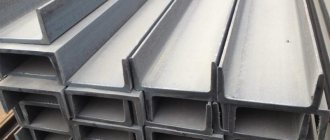
However, if metal structures have a complex shape, this method is not used. This can be explained very simply: calculating the channel area is a complex process, and for openwork products it is not at all a feasible task. In these cases, it is customary to calculate the cost of painting metal structures per 1 ton, which significantly simplifies the process and avoids errors.
Today, a large number of coefficients are used to calculate the area to paint metal structures.
Below are tables with coefficients for correct calculation.
| Profile name, number and section thickness | Surface area, sq.m/1 t. profile | Profile name, number and section thickness | Surface area, sq.m/1 t. profile | Profile name, number and section thickness | Surface area, sq.m/1 t. profile | ||
Sheet steel and open bent profiles
(the surface is shown as a total on both sides)
sheet thicknesssheet thicknesssheet thickness2,0127,67,036,622,011,82,2115,98,032,125,010,42,5102,39,028,528,09,42,891,210,025,730,08,738511,023,432,08,23, 279,912,021,536,07,33,573,014,018,440,06,64,063,916,016,245,05,95,051,118,014,450,05,46,042,720,013,055 .04.9Reinforcement cross-sectional area
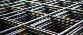
Reinforcement is a metal product in the form of a rod used in construction. A reinforcement section is an image of a figure formed by cutting the reinforcement by a plane in the transverse direction.
Formula for calculating the cross-sectional area of reinforcement: S = π * d 2 / 4
, where d is the diameter of the reinforcement.
Reinforcement section
You need to know about the cross section and calculate (you need to know the S-circle). It is calculated by the formula: The area of a circle is found by the formula: PxR2, where R2 is the radius of the circle; P-3.14. For rods with a diameter of 14 mm, the calculation will be as follows:
R=14:2:1000=0.007 m.
S=3.14×0.007×0.007=0.0001;
Next, we determine the V rod. You need to know the length of the product in meters (for example, 14m). V=14×0.0001=0.014;
- Then we multiply the obtained result by the volumetric weight of the product 0.014 * 7856 = 109 kg.
- The weight of the rod is very important for construction, therefore, correct calculations will help make a reliable foundation that can last a long time and can withstand heavy loads.
- Table of fittings assortment GOST 5781-82:
Reinforcement is produced by hot rolling. After the material reaches the plant, it is unloaded, carefully sorted and placed in a liquid state for melting. Next it is poured into a mold.
After the steel ingots harden, they are heated. After this procedure, the product is placed in a refrigeration chamber to cool, quality control, cutting and preparation for transportation are carried out.
The reinforcement is produced in the form of rods or coils.
How to determine the area of reinforcement: calculation table
The cross-sectional area of the reinforcement is one of the most important parameters determining strength. The higher the expected load, the larger the area should be. To find out this data, you need to contact your sales consultant or read the product data sheet. If the product is purchased second hand, you will have to make the calculation yourself.
To do this, you must follow these instructions:
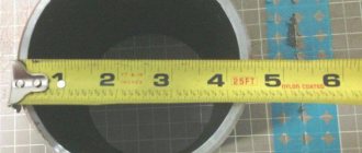
- Measure the diameter. A caliper will help. It is necessary to take into account that the result may not be a round unit, so it is rounded based on mathematical rules.
- Determine the cross-sectional area of the reinforcement based on its diameter using a special table. With its help, you can calculate how much 1 meter of reinforcement weighs and how many meters are in a ton of reinforcement.
Reinforcement assortment table, weight of 1 meter and diameter.
| Cross section, area, cm² | Diameter of fittings, mm | Weight of linear meter of reinforcement, g | How much reinforcement in a ton, m |
| 0,283 | 6 | 222 | 4505 |
| 0,503 | 8 | 395 | 2532 |
| 0,785 | 10 | 617 | 1620 |
| 1,131 | 12 | 888 | 1126 |
| 1,54 | 14 | 1210 | 826 |
| 2,01 | 16 | 1580 | 633 |
| 2,64 | 18 | 2000 | 500 |
| 3,14 | 20 | 2470 | 405 |
| 3,8 | 22 | 2980 | 336 |
| 4,91 | 25 | 3850 | 260 |
| 6,16 | 28 | 4830 | 207 |
| 8,04 | 32 | 6310 | 158 |
| 10,18 | 36 | 7990 | 125 |
| 12,58 | 40 | 9870 | 101 |
| 15,48 | 45 | 12480 | 80 |
Thanks to the table, you can easily determine other data, for example, how many meters are in a ton of 12 mm reinforcement. We look for indicator 12 in the diameter column and find the corresponding value in the length column. This parameter is 1126 m.
Closed bent square, rectangular and pipe profiles
(the surface is shown on the outside of the rental)
wall thicknesswall thicknesswall thickness2,065,28,016,618,07,52,552,19,014,520,06,73,043,510,013,122,06,13,537,311,011,825,05,54,032,912,010,828,05,05, 026,514,09,330,04,76,022,016,08,132,04,47,019,017,07,640,03,5Calculation of the cross-section of a stranded conductor
Stranded wire consists of several individual wires. Its cross section is calculated as follows:
- The indicator of the cross-sectional area of one core is found.
- Cable cores are recalculated.
- The quantity is multiplied by the cross-section of one core.
When connecting a stranded conductor, its ends are crimped with a special sleeve using crimping pliers.
Equal flange angle steel
half-kit thickness half-kit thickness shelf thickness 3,086,59,029,520,013,34,065,010,026,322,012,05,052,012,022,025,010,66,044,014,019,028,09,67,037,016,016,630,09 .08.033.018.014.9Hot rolled channels
(the surface is shown as a total on all sides)
profile number profile number profile number 547,11640,522А34,96,546,416А38,72435,0845,41839,324А33,31044,718А37,72733,21243,12038,33031,41441,620А36,43329,614А3 9.72236.63627.74026.1Table of dependence of the current of the circuit breaker (fuse) on the cross-section
(Addition to article, June 2014)
And here is how the Germans treat the maximum current depending on the cross-sectional area of the wire. In the right column is a recommendation for choosing an automatic (protective) switch.
Table 3
Table for selecting a circuit breaker for different wire cross-sections
As you can see, the Germans are playing it safe and are providing for a larger reserve compared to us.
Although, perhaps this is because the table was taken from instructions from “strategic” industrial equipment.
Regarding the selection of wires, I usually use catalogs from online stores, here is an example of copper. They have the largest selection I've ever seen. It’s also good that everything is described in detail - composition, applications, etc.
A good Soviet book on the topic of the article:
• Karpov F. F. How to choose the cross-section of wires and cables, 1973 / Brochure from the Electrician's Library. Provides instructions and calculations necessary for selecting cross-sections of wires and cables up to 1000 V. Useful for those interested in primary sources., zip, 1.57 MB, downloaded: 4580 times./
I-beams
(the surface is shown as a total on all sides)
profile number profile number profile number 1044,42038,13626,71243,12236,74024,91441,82434,44523,21640,52733,05021,41839,13031,25519,76018,1Beams with parallel flange edges
(the surface is shown as a total on all sides)
profile number profile number profile number 20Bx49,140Bx34,970Bx21,020B139,440B130,870B119,120B236,740B227,870B217,420B333,640B325,570B315,823Bx45,945B32,370B41 4.623B13845B127.580B19.323B235.345B224.980B117.223B33250B322.880B215.526Bx43.250Bx29 ,380B314.226B135.950B124.880B413.126B233.350B222.890Bx17.826B330.455B320.390B115.730Bx40.755Bx26.790B214.530B135.455B122.69 0B313.230B233.055B220.890B412.030B330.160B319.1100Bx16.735Bx37.860Bx24.4100B114 ,435B134,460B120,5100B213,035B231,160B218,6100B311,735B328,460B317,2100B410.6Materials
Determination of surface area when painting steel structures
Gosstroy of the USSR in a letter dated May 23, 1985. No. AD-2314-4 established the procedure for determining the surface area of steel structures.
The total surface area of the rolled profiles that make up the structure is determined in square meters by multiplying the total mass of the rolled profiles that make up the structure by the corresponding surface area values (given below) contained in 1 ton of rolled steel sections.
| Profile name, number and section thickness | Surface area, sq.m/1 t. profile | Profile name, number and section thickness | Surface area, sq.m/1 t. profile | Profile name, number and section thickness | Surface area, sq.m/1 t. profile |
| Sheet steel and open bent profiles (surface shown is total on both sides) | |||||
| sheet thickness | sheet thickness | sheet thickness | |||
| 2,0 | 127,6 | 7,0 | 36,6 | 22,0 | 11,8 |
| 2,2 | 115,9 | 8,0 | 32,1 | 25,0 | 10,4 |
| 2,5 | 102,3 | 9,0 | 28,5 | 28,0 | 9,4 |
| 2,8 | 91,2 | 10,0 | 25,7 | 30,0 | 8,7 |
| 3 | 85 | 11,0 | 23,4 | 32,0 | 8,2 |
| 3,2 | 79,9 | 12,0 | 21,5 | 36,0 | 7,3 |
| 3,5 | 73,0 | 14,0 | 18,4 | 40,0 | 6,6 |
| 4,0 | 63,9 | 16,0 | 16,2 | 45,0 | 5,9 |
| 5,0 | 51,1 | 18,0 | 14,4 | 50,0 | 5,4 |
| 6,0 | 42,7 | 20,0 | 13,0 | 55,0 | 4,9 |
| Closed bent square, rectangular and pipe profiles (the surface is given on the outside of the rolled product) | |||||
| wall thickness | wall thickness | wall thickness | |||
| 2,0 | 65,2 | 8,0 | 16,6 | 18,0 | 7,5 |
| 2,5 | 52,1 | 9,0 | 14,5 | 20,0 | 6,7 |
| 3,0 | 43,5 | 10,0 | 13,1 | 22,0 | 6,1 |
| 3,5 | 37,3 | 11,0 | 11,8 | 25,0 | 5,5 |
| 4,0 | 32,9 | 12,0 | 10,8 | 28,0 | 5,0 |
| 5,0 | 26,5 | 14,0 | 9,3 | 30,0 | 4,7 |
| 6,0 | 22,0 | 16,0 | 8,1 | 32,0 | 4,4 |
| 7,0 | 19,0 | 17,0 | 7,6 | 40,0 | 3,5 |
| Equal flange angle steel | |||||
| shelf thickness | shelf thickness | shelf thickness | |||
| 3,0 | 86,5 | 9,0 | 29,5 | 20,0 | 13,3 |
| 4,0 | 65,0 | 10,0 | 26,3 | 22,0 | 12,0 |
| 5,0 | 52,0 | 12,0 | 22,0 | 25,0 | 10,6 |
| 6,0 | 44,0 | 14,0 | 19,0 | 28,0 | 9,6 |
| 7,0 | 37,0 | 16,0 | 16,6 | 30,0 | 9,0 |
| 8,0 | 33,0 | 18,0 | 14,9 | ||
| Hot-rolled channels (the total surface is shown on all sides) | |||||
| profile number | profile number | profile number | |||
| 5 | 47,1 | 16 | 40,5 | 22A | 34,9 |
| 6,5 | 46,4 | 16A | 38,7 | 24 | 35,0 |
| 8 | 45,4 | 18 | 39,3 | 24A | 33,3 |
| 10 | 44,7 | 18A | 37,7 | 27 | 33,2 |
| 12 | 43,1 | 20 | 38,3 | 30 | 31,4 |
| 14 | 41,6 | 20A | 36,4 | 33 | 29,6 |
| 14A | 39,7 | 22 | 36,6 | 36 | 27,7 |
| 40 | 26,1 | ||||
| I-beams (the surface is the total on all sides) | |||||
| profile number | profile number | profile number | |||
| 10 | 44,4 | 20 | 38,1 | 36 | 26,7 |
| 12 | 43,1 | 22 | 36,7 | 40 | 24,9 |
| 14 | 41,8 | 24 | 34,4 | 45 | 23,2 |
| 16 | 40,5 | 27 | 33,0 | 50 | 21,4 |
| 18 | 39,1 | 30 | 31,2 | 55 | 19,7 |
| 60 | 18,1 | ||||
| I-beams for monorails (the total surface is shown on all sides) | |||||
| profile number | profile number | profile number | |||
| 24M | 24 | 36M | 21,4 | ||
| 30M | 22,3 | 45M | 19,3 | ||
| Beams with parallel flange edges (the surface is the total on all sides) | |||||
| profile number | profile number | profile number | |||
| 20Bx | 49,1 | 40Bx | 34,9 | 70Bx | 21,0 |
| 20B1 | 39,4 | 40B1 | 30,8 | 70B1 | 19,1 |
| 20B2 | 36,7 | 40B2 | 27,8 | 70B2 | 17,4 |
| 20B3 | 33,6 | 40B3 | 25,5 | 70B3 | 15,8 |
| 23Bx | 45,9 | 45B | 32,3 | 70B4 | 14,6 |
| 23B1 | 38 | 45B1 | 27,5 | 80B | 19,3 |
| 23B2 | 35,3 | 45B2 | 24,9 | 80B1 | 17,2 |
| 23B3 | 32 | 50B3 | 22,8 | 80B2 | 15,5 |
| 26Bx | 43,2 | 50Bx | 29,3 | 80B3 | 14,2 |
| 26B1 | 35,9 | 50B1 | 24,8 | 80B4 | 13,1 |
| 26B2 | 33,3 | 50B2 | 22,8 | 90Bx | 17,8 |
| 26B3 | 30,4 | 55B3 | 20,3 | 90B1 | 15,7 |
| 30Bx | 40,7 | 55Bx | 26,7 | 90B2 | 14,5 |
| 30B1 | 35,4 | 55B1 | 22,6 | 90B3 | 13,2 |
| 30B2 | 33,0 | 55B2 | 20,8 | 90B4 | 12,0 |
| 30B3 | 30,1 | 60B3 | 19,1 | 100Bx | 16,7 |
| 35Bx | 37,8 | 60Bx | 24,4 | 100B1 | 14,4 |
| 35B1 | 34,4 | 60B1 | 20,5 | 100B2 | 13,0 |
| 35B2 | 31,1 | 60B2 | 18,6 | 100B3 | 11,7 |
| 35B3 | 28,4 | 60B3 | 17,2 | 100B4 | 10,6 |
| Wide-flange beams (the total surface is shown on all sides) | |||||
| profile number | profile number | profile number | |||
| 20Shx | 38,9 | 40Shx | 23,2 | 70Ш1 | 15,8 |
| 20Ш1 | 33,8 | 40Ш1 | 20,4 | 70Ш2 | 14,4 |
| 20Ш2 | 31,2 | 40Ш2 | 18,9 | 70Ш3 | 13,1 |
| 23Shx | 37,9 | 40Ш3 | 17,9 | 70Ш4 | 12,0 |
| 23Ш1 | 30,9 | 40Ш4 | 16,2 | 70Ш5 | 11,0 |
| 23Ш2 | 27,8 | 50Sh | 22,6 | 70Ш6 | 10,3 |
| 26Shx | 33,2 | 50Ш1 | 19,4 | 70Ш7 | 19,5 |
| 26Ш1 | 28,6 | 50Ш2 | 17,4 | 70Ш8 | 8,8 |
| 26SH2 | 25,9 | 50Ш3 | 15,7 | 80Ш | 17,4 |
| 30Shx | 30,1 | 50Ш4 | 14,2 | 80Ш1 | 14,4 |
| 30Ш1 | 26,0 | 50Ш5 | 12,9 | 80Ш2 | 13,2 |
| 30Ш2 | 23,4 | 60Ш | 21,4 | 80Ш3 | 12,1 |
| 30Ш | 21,1 | 60Ш1 | 17,4 | 90Ш | 15,7 |
| 30Ш4 | 19,4 | 60Ш2 | 16,0 | 90Ш1 | 13,1 |
| 35Ш1 | 22,7 | 60Ш4 | 13,1 | 90Ш3 | 11,1 |
| 35Ш2 | 20,8 | 60Ш5 | 11,8 | 100Sh | 14,2 |
| 35Ш3 | 19,1 | 60Ш6 | 10,7 | 100Ш1 | 12,3 |
| 35Ш4 | 17,3 | 70Ш | 19,7 | 100Ш2 | 11,3 |
| I-beam columns (the total surface is shown on all sides) | |||||
| profile number | profile number | profile number | |||
| 20K | 32,3 | 30K1 | 21,4 | 35K8 | 10,0 |
| 20K1 | 29,6 | 30K2 | 19,9 | 40K | 19,9 |
| 20K2 | 26,1 | 30K3 | 18,3 | 40K1 | 17,5 |
| 20K3 | 23,7 | 30K4 | 16,7 | 40K2 | 16,0 |
| 20K4 | 21,7 | 30K5 | 15,2 | 40K3 | 14,5 |
| 23K | 31,6 | 30K6 | 14,1 | 40K4 | 13,1 |
| 23K1 | 27,5 | 30K7 | 12,8 | 40K5 | 11,8 |
| 23K2 | 25,7 | 30K8 | 11,7 | 40K6 | 10,8 |
| 23K3 | 23,2 | 35K1 | 19,3 | 40K7 | 9,8 |
| 23K4 | 21,9 | 35K2 | 17,3 | 40K8 | 9,0 |
| 26K1 | 26,1 | 35K3 | 15,6 | 40K9 | 8,2 |
| 26K2 | 23,3 | 35K4 | 14,2 | 40K10 | 7,8 |
| 26K3 | 20,9 | 35K5 | 13,0 | 40K11 | 6,2 |
| 26K4 | 19,2 | 35K6 | 11,9 | 40K12 | 5,2 |
| 26K5 | 17,6 | 35K7 | 10,9 | 40K13 | 4,4 |
| 40K14 | 3,7 | ||||
In the case where the steel structure is of a composite cross-section, the area of painting of the steel structures can be determined by enlarged conversion factors.
from the Directory “Major repairs of buildings. Estimator's Handbook." Volume 2 p.256. Moscow. Stroyizdat. 1991 and “Estimated standardization and pricing of construction work, p. 106, 1989.” author P.E. Komarovsky
| Characteristics of metal structures | Area, m2, per 1 ton of structures (conversion factor) |
| Structures with an uneven ratio of steel profiles | 23 |
| Structures with a predominance of angle steel | 27 |
| Structures with a predominance of sheet and universal steel | 19 |
| Structures with a predominance of channels and beams | 29 |
| Structures made of sheet steel 2.5-4.5 mm thick | 24 |
| Structures made of sheet steel with a thickness of over 5 mm | 19 |
| Bindings from special profiles | 75 |
Wide flange beams
(the surface is shown as a total on all sides)
profile number profile number profile number 20Wx38.940Wx23.270W115.820W133.840W120.470W214.420W231.240W218.970W313.123Wx37.940W317.970W412.023W130.940W416.270W5 11,023Ш227,850Ш22,670Ш610,326Шх33,250Ш119,470Ш719,526Ш128,650Ш217,470Ш88 ,826SH225,950SH315,780SH17,430SH30,150SH414,280SH114,430SH126,050SH512,980SH213,230SH223,460SH21,480SH312,130SH21,160SH117,490SH15,730SH41 9,460Ш216,090Ш113,135Ш122,760Ш413,190Ш311,135Ш220,860Ш511,8100Ш14,235Ш319 ,160Ш610,7100Ш112,335Ш417,370Ш19,7100Ш211,3I-beam columns
(the surface is shown as a total on all sides)
profile number profile number profile number 20K32,330K121,435K810,020K129,630K219,940K19,920K226,130K318,340K117,520K323,730K416,740K216,020K421,730K515,240K314 ,523K31,630K614,140K413,123K127,530K712,840K511,823K225,730K811,740K610 ,823K323,235K119,340K79,823K421,935K217,340K89,026K126,135K315,640K98,226K223,335K414,240K107,826K320,935K513,040K116,226K4 19.235K611,940K125,226K517,635K710,940K134,440K143.7