What is a thyristor, its structure and designation on the diagram
A thyristor is a semiconductor element that has only two states: “open” (current flows) and “closed” (no current). Moreover, both states are stable, that is, the transition occurs only under certain conditions. The switching itself occurs very quickly, although not instantly.
In terms of its mode of action, it can be compared to a switch or a key. But the thyristor switches using voltage, and turns off when the current is lost or the load is removed. So the operating principle of a thyristor is not difficult to understand. You can think of it as an electrically controlled key. Well, not really.
A thyristor usually has three outputs. One control and two through which current flows. You can try to briefly describe the principle of operation. When voltage is applied to the control output, the circuit is switched through the anode-collector. That is, it is comparable to a transistor. The only difference is that in a transistor, the amount of current passed depends on the voltage applied to the control terminal. And the thyristor is either completely open or completely closed.
Checking the thyristor for serviceability
The device can be checked in several ways, one of them is using a special homemade tester, assembled according to the diagram below:
This circuit is designed to operate at a voltage of 9-12 V. For other supply voltage values, the values of R1-R3 are recalculated.
Verification steps:
- The positive pole is connected to the anode, and “-” is connected to the cathode.
- Using the SA button, a signal is sent to the control electrode to open the device.
- If the LED lights up before pressing the SA button or does not light up after pressing, then the device is inoperative.
The essence of the device
The term “thyristor” comes from the merger of two words: the Greek hýra - door or entrance and the English resistor - resisting. This name was given to a semiconductor device made on the basis of a single crystal of a semiconductor substance and having three or more pn junctions. During operation, this device can have two stable positions:
- closed - corresponding to low conductivity;
- open - offering no resistance to the passage of current.
That is, to paraphrase the definitions, we can say that the thyristor works like a key, by analogy with a door. In one of its states, the lock on the door is open, and people can freely pass through it (electric current), and in the other, it is closed and the door is locked. Therefore, it is often called an electronic switch. In scientific terms, its correct name sounds like a semiconductor with a controlled valve (diode).
The adoption of one of the stable states by an element occurs quickly, but not instantly. To change one to the other, voltage is used. When it is present, the thyristor is in the open state, and when not, it closes. For this, a special additional pin is used. Therefore, the device has three outputs and looks like a transistor. At the same time, their principle of operation is similar, only, unlike a transistor, a thyristor either completely passes the current or prevents its passage.
Characteristics and parameters
A thyristor is a device that simultaneously combines three functions: a rectifier, a switch and an amplifier. The main properties characterizing the device can be presented in the form of the following points:
- A thyristor, like a diode, passes current only in one direction, that is, it works as a rectifier;
- the device switches from one state to another using voltage;
- the amount of current required to switch a thyristor is on the order of several milliamps, while it can pass tens of amperes through itself;
- By changing the time of the applied signal to the control pin, you can regulate the average value of the current flowing through the load, in other words, control the power.
The main function that describes the operation of the device is the current-voltage characteristic (volt-ampere characteristic). It is a flat coordinate system along the Y axis, on which the load current is plotted, and along the X axis, the voltage on the control electrode. Based on the type of nonlinearity of the correspondence between these two quantities, the current-voltage characteristic belongs to the S-type devices.
The characteristic uses letter designations corresponding to key points in the operation of the thyristor. Thus, the coordinate (Vbo; IL) corresponds to the moment of switching on, and the point with coordinates (Vн; Iл) corresponds to the open state. The zone lying on a segment with coordinates (Vbo; IL) and (Vн; In) is considered transitional, that is, unstable.
A thyristor device, in addition to the current-voltage characteristic, is characterized by a number of parameters:
- The highest constant reverse voltage is the value above which a breakdown of the junction occurs.
- Turn-on voltage is the signal value, upon reaching which the element is unlocked.
- Allowable current is the maximum value that a radio device can pass through without changing its characteristics.
- Holding current is the current flowing through the anode and causing the cell to lock.
- Voltage drop - shows the amount of energy that is dissipated by the device (0.5 -1 V).
- Maximum power is determined by the permissible current and the maximum possible voltage applied to the controlled terminals, that is, the nature of the load.
- Turn-off time is the period of time during which the thyristor will completely close. Amounts to microseconds.
- Opening constant control current - indicates the value that is necessary to maintain the device in the open state (anode-cathode). Typically around 100 mA.
We recommend reading: Twisted pair: what is it, crimping diagram
Volt-ampere characteristics
The operating principle of a thyristor is clearly demonstrated by its current-voltage characteristic. It, like the characteristic of a conventional diode, is located in the I and III quadrants and consists of positive and negative branches. The negative branch is also similar to the diode branch and contains a section in which the device is locked - from zero to Ubreakdown. When the threshold voltage is reached, an avalanche breakdown occurs.
The positive branch requires careful consideration. If you apply direct voltage to the thyristor and begin to increase it, the current will grow slowly - the resistance of the closed semiconductor device is high. This is the red section of the graph. When a certain level is reached, the thyristor opens abruptly, its resistance decreases, the voltage drop also decreases, and the current increases - the blue section. This area is characterized by negative resistance, but the device behaves unstable here, with a pronounced tendency to transition to the open state.
Next, the thyristor enters the mode of a conventional diode - the green branch of the graph. This is how a diode thyristor works, and the ability to open when a certain level is reached is called the dinistor effect.
Device design
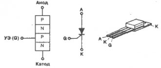
Any thyristor device has at least three terminals: anode, cathode and input. They are produced by various manufacturers and can be in the form of a tablet or a pin. As a rule, the material for their manufacture is silicon. It provides good thermal conductivity and can withstand high power.
Emitter junctions are made using alloy technology, and collector junctions are made using the diffusion method. Planar technology is also used. The concentration of impurities in the emitter regions is much greater than in the base regions. In this case, the thickest layer is the central one. These two factors - thickness and low concentration - allow the device to withstand a fairly large reverse voltage (on the order of hundreds of volts). The anode of the device is connected to the body of the product, which ultimately has a positive effect on heat dissipation.
Asymmetrical thyristors have a slightly different design. In their design, the cathode is connected to the n+ and p zone, and the anode to the p+ and n region. Such connections are called anodic or cathodic short circuits. Their use leads to the appearance of additional resistance between the transitions. This connection reduces transient processes and the lifetime of the main carriers.
The simplest design of a thyristor includes a base connected to a semiconductor crystal and serving as an anode, a cathode terminal, and a control electrode. On top of the crystal is covered with an insulator and a lid, which helps protect the device from mechanical damage and at the same time serves as a heat sink.
Start testing the thyristor with a multimeter
First, take the trouble to determine the location of the electrodes:
- cathode;
- anode;
- control electrode (base).
To open the thyristor switch, the cathode of the device is supplied with a minus (black multimeter probe), and a plus (red multimeter probe) is connected to the anode. The tester is set to ohmmeter mode. The resistance of an open thyristor is low. Stop setting the limit to 2000 Ohms. It's time to remind you: the thyristor is capable of being controlled (opened) by positive or negative pulses. In the first case, we close the anode to the base with a jumper made of a thin pin, in the second - the cathode. Here and there the thyristor should open, as a result the resistance will become less than infinity.
The testing process comes down to understanding what voltage the thyristor is controlled by. Negative or positive. Try this and that (if there is no marking). One attempt will definitely work if the thyristor is working properly.
The process then diverges from testing the transistor. If the control signal disappears, the thyristor will remain open if the current exceeds the holding threshold. The key may close. If the current does not reach the holding threshold.
- The holding current is specified by the technical characteristics of the thyristor. Take the trouble to download complete documentation from the Internet and be aware of things.
- A multimeter determines a lot. What voltage is supplied to the probes (traditionally 5 volts), how much power will it provide. You can check with the help of a large capacitor. You need to correctly connect the probes to the terminals of the device in resistance measurement mode, wait until the numbers on the display increase from zero to infinity. The capacitor has completed the charging process. Now let's switch to the DC voltage measurement mode and see the magnitude of the potential difference on the legs of the capacitor (the multimeter is in resistance measurement mode). Based on the current-voltage characteristics of the thyristor, it is easy to determine whether the value is sufficient to create a holding current.
Dinistors ring easier. Try to open the key. Depends on whether the power of the multimeter is enough to overcome the barrier. To guarantee a thyristor test, it is better to assemble a separate circuit. Like the one shown in the picture. The diagram is formed by the following elements:
- Three resistors will serve to set the thyristor mode. One rated at 300 ohms limits the current. If a parameter needs to be changed, it is extremely difficult to overdo it when +5 volts are available. It's okay if you remove the resistor. Try to be guided by the current-voltage characteristics of the thyristor. It is ideal to install a variable resistor with a range of 100 - 1000 Ohms. The two resistors on the right branch set the operating point. In the circuit, 2.5 volts are supplied to the control electrode. If it does not agree with the current-voltage characteristics of the thyristor (see documentation), change the ratings. They form a resistive divider. The 5 volt voltage is divided proportionally to the ratings. Since the resistances are equal to each other, exactly half of the supply voltage reaches the control electrode.
- The LED will serve as a load. It is located in the “power” branch, next to it there is an emitter and a collector. Here, after opening the key, current should flow. The LED will light up, we will see if the thyristor is working. The LED is not infrared. Take the visible range.
Thyristor test circuit
- The thyristor forms the center of the circuit. It is better to solder the sockets into which you can quickly plug in a new test sample. Otherwise, there is no point in planting a vegetable garden. Please note that the circuit is assembled for the case when the thyristor is controlled by a voltage of positive polarity. It is better to find a separate power source. For example, a battery, a PC system unit, an accumulator. The positive pole connects the circuit to ground, the negative pole is fed to the base. Moreover, you will have to remove the resistor from the left branch.
- The button will help you find out with guarantee: the experiment has begun. Without it, control voltage is not supplied. Just press the button and release it, and you will see the result. The LED will light up and go out - the holding current is not maintained, the thyristor is working. Sometimes the LED will remain on, depending on its characteristics.
Why did you choose +5 volt power? The voltage is easy to find on the phone adapter (charger). Take a closer look: there is an inscription like 5V– /420 mA. Output values of voltage, current (immediately see if the thyristor is enough to hold). Every expert knows: +5 volts are available on the USB bus. Almost any gadget, computer, is now equipped with a port (in different formats). Avoid problems with nutrition. Just in case, let's take a closer look at this point.
Purpose of the device
Thyristors are semiconductor devices with three (or more) pn junctions intended for use as electronic switches in electrical current switching circuits. They switch electrical circuits, regulate voltage, and convert direct current into alternating current.
In design and principle of operation, it is very similar to a semiconductor diode, but unlike it, the thyristor is controlled. The “key” nature of the action of the trinistor allows it to be used for switching electrical circuits where previously only electromagnetic relays served for this purpose.
Semiconductor switches are lighter, more compact and many times more reliable in operation than electromagnetic relays with mechanically closed contacts. Unlike such relays, they switch at a very high speed - hundreds and thousands of times per second, and if necessary - even faster. SCRs are used in modern electrical communication equipment, in high-speed remote control systems, in computers and in energy devices.
Types of thyristors
Lockable ones were discussed above, but there are many more types of semiconductor thyristors that are also worth mentioning. Certain types of thyristors are used in a variety of designs (chargers, switches, power regulators). Somewhere it is required that control be carried out by supplying a stream of light, which means an optothyristor is used. Its peculiarity is that the control circuit uses a semiconductor crystal that is sensitive to light. The parameters of thyristors are different, they all have their own characteristics that are characteristic only of them. Therefore, you need to at least have a general idea of what types of these semiconductors exist and where they can be used. So, here is the entire list and the main features of each type:
- Thyristor diode. The equivalent of this element is a thyristor, to which a semiconductor diode is connected back-to-back.
- Dinistor (diode thyristor). It can go into full conduction if a certain voltage level is exceeded.
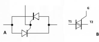
- Triac (symmetrical thyristor). Its equivalent is two thyristors connected back-to-back.
- The high-speed inverter thyristor has a high switching speed (5... 50 μs).
- Thyristors with field effect transistor control. You can often find designs based on MOS transistors.
- Optical thyristors that are controlled by light flows.
The operating principle of thyristors
In specialized literature, a thyristor is called “single-operational” and belongs to the group of incompletely controlled radio components. It goes into the active state when receiving a pulse of a certain polarity from the control object. The speed of activation and subsequent functioning is influenced by:
- nature of the load – inductive, reactive;
- load current value;
- speed and amplitude of increase in the control pulse;
- device environment temperature;
- voltage level.
Switching from one state to another is carried out using control signals. To completely turn off the thyristor, additional steps are required. Shutting down is carried out in several ways:
- natural shutdown (natural switching);
- forced shutdown (forced switching), this option can be carried out in many ways.
During operation, unplanned switching from one position to another is possible, which is provoked by changes in the characteristics of electricity and temperature.
Principle of operation
Thyristors are essentially switching devices. The structure of a simple element consists of npnp layers and has three transitions. Two of them work in the forward direction, and one in the reverse direction. The device has two outer regions called anode (p) and cathode (n). To understand the principle of operation of a thyristor, it can be represented as dual transistors: npn and pnp. In this case, the middle zone of the second transistor (n) is connected to the outer zone of the first.
We recommend reading: Connecting an electric motor from 380 to 220: diagrams and methods of connecting an electric motor with photos and videos
As a result, it turns out that the outer zones will be emitter junctions, and the middle zones will be collector junctions. The base area of the first element will coincide with the collector of the second and vice versa. Based on this, the collector current of the transistors will also be the base current.
The physical processes occurring in the element can be described as follows. If there was only one junction in the device, only a reverse current would arise, caused by minority charge carriers. If a direct voltage is applied to the emitter junction, the collector current will increase and the voltage across it will decrease. In a transistor, to switch it to saturation mode (maximum throughput), a direct voltage is applied to the emitter, and between the base and collector it is reduced to single values.
Same thing in a thyristor. Minority charges are injected through the junctions of the anode and cathode, leading to a decrease in the resistance of the control electrode. When direct voltage is applied, that is, a negative potential is applied to the cathode, and a positive potential is applied to the anode, a small current begins to flow through the device. This state corresponds to the closed position.
An increase in voltage leads to the injection of carriers into the controlled junction. As a result, on the one hand, its resistance increases due to depletion of the majority carriers, since the junction turns on in the opposite direction, and on the other hand, it increases due to the entry of new charges into its region.
When the voltage reaches a certain value, these two phenomena are balanced, and even an increase in voltage by a small amount leads to an avalanche-like process of unlocking the thyristor. This state resembles the saturation mode of a transistor. The junction resistance becomes minimal, and the current value is determined by the load resistance.
Thyristor operating modes
The thyristor has three operating modes:
- Forward lock
- Reverse blocking
- Forward conduction
Forward lock
In this state or mode, forward conduction of current is blocked. The top diode and bottom diode are forward biased and the junction in the center is reverse biased. Thus, the thyristor does not turn on because the gate does not fire and no current flows through it.
Reverse blocking
In this mode, the connection between the anode and cathode is reversed and no current flows through it. Thyristors can only conduct current in one direction and it blocks in the opposite direction, so the flow of current is blocked.
Forward conduction
When current is applied to the gate, the thyristor is triggered and it begins to conduct current. It remains on until the forward current drops below a threshold, and this can be achieved by turning off the circuit.
DC circuit
In a direct current circuit, a thyristor operates on the principle of delivering a pulse of positive polarity, of course, relative to the cathode. The duration of the transition from one state to another is greatly influenced by a number of characteristics. Namely:
- Type of load (inductive, active, etc.).
- The rate of rise of the pulse and its amplitude, meaning the load current.
- The magnitude of the current load itself.
- Voltage in the circuit.
- The temperature of the device itself.
The most important thing here is that there is no sudden increase in voltage in the network where this device is installed. In this case, the thyristor may turn on spontaneously, and the control signal will be absent at this time
AC circuit
In this network, the thyristor switch works a little differently. This device makes it possible to perform several types of operations. Eg:
- Switching on and off a circuit in which an active or active-reactive load acts.
- You can change the value of the effective load and its average value due to the ability to change (adjust) the supply of the control signal itself.
Thyristor in an alternating current circuit.
But keep in mind that a thyristor switch can only pass a signal in one direction. Therefore, the thyristors themselves are installed in the circuit, so to speak, in an anti-parallel connection.
Two-transistor analogy of a thyristor
The collector current from the NPN transistor is supplied directly to the base of the PNP transistor and the collector current of the PNP transistor is supplied to the base of the NPN transistor. These connected transistors rely on each other for conduction.
Thus, a base current is required to conduct one of the transistors. When the anode terminal of the thyristor is negative with respect to the cathode, the NP junction becomes forward biased and the PN junction becomes reverse biased.
We recommend reading: How to check a battery with a multimeter: for performance
Two transistor analogues of a thyristor
Here the reverse current flow is blocked until the breakdown voltage is applied. After the breakdown voltage, it begins to conduct without a gate signal being applied. This is one of the negative characteristics of thyristors, since it triggers conduction when the voltage is reversed.
When the anode terminal is made positive with respect to the cathode, the outer junctions are forward biased and the central NP junction is reverse biased and blocks forward current. Thus, to induce it into conduction, a positive current is applied to the base of the transistors.
The two transistors are connected in a regenerative circuit and this causes the transistor to conduct saturation. Thus, we can say that thyristors block current both in the direction of the AC source in the off state, and can be turned on by applying a positive current to the base of the transistor.
Thyristor in an electrical circuit: what kind of semiconductor is it
If we use scientific terms, we can see that the design of this complex electronic device includes a semiconductor single crystal with three or more pn junctions.
They are made in order to change its conductivity to two critical states, when it:
- It is open and allows electric current to pass through it.
- Completely closed.
To connect to an electrical circuit, it is usually equipped with three, two or four leads from the contact pads of the pn layers.
I will not continue this topic in scientific language, because beginners will not understand anything, and it is difficult for me to explain in simple terms how charge carriers (holes and electrons) move throughout this structure in each specific case.
And no one needs this now except students trying to pass an exam, and workers designing and developing new devices.
A home electrician simply needs to understand the operating principle of the final device in order to be able to check its serviceability and competently operate it in everyday life.
Therefore, I show the final result - what the volt-ampere characteristic of the thyristor looks like during its operation.
It highlights two areas of the operating state with direct and reverse application of voltage, forming five modes depicted in the picture. Let’s not go deep into the theory and draw some brief conclusions for ourselves:
- at the initial stage of the forward bias region, the semiconductor is closed, then it opens and remains open;
- when connected back to the voltage source, it initially does not pass current, but when it reaches a critical state, it breaks through.
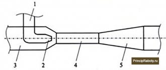
What does a thyristor look like and is indicated on electrical diagrams?
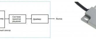
Modern industry uses a huge range of these unique semiconductors. They are available in different housings with the capabilities of transmitting and switching various powers.
I present the appearance of only a small part of them, manufactured in a metal case designed to work in power circuits with high currents.
There are also designs produced in a plastic case, which allows switching currents of lower values. They are used in control circuits of various household devices.
Externally, a thyristor looks like a diode.
Only in most cases it has an additional terminal for connecting to an external circuit - a control electrode. The designation on the diagram is also approximately the same.
The change concerns only a small addition to the cathode terminal - a small broken line. All this is clearly visible when compared.
It is no coincidence that the appearance of diodes and thyristors, as well as their designations on the diagrams, are similar. Although they are slightly different in design, they work according to the general principle: they pass electric current only in one direction.
I present this question more specifically below.
How to easily understand the operating principles and scientific terms of this complex semiconductor: 2 mneumonic rules
Commandment No. 1 for a beginner
Let's imagine that we are rafting on a large raft along a wide river. We can only move with the flow, and not against it. The flow of water moves due to the difference in heights (potentials), which have different levels of potential energy.
So the current in the diode can only flow in one direction: from the anode to the cathode. A different movement of electrons blocks the semiconductor transition. There are no other means of regulation here.
All this fully corresponds to the operation of a thyristor, but with small additions: the diode immediately opens when voltage is directly applied to its terminals.
In this case, the thyristor is closed and does not conduct current. It acts like a dam with locks blocking the river. Our raft will simply stop in front of the obstacle that has arisen. To resume movement, he needs to open the water barrier gate.
All this is done by command, when a current pulse of a certain direction is supplied through the control electrode, for example, to the anode (with appropriate control).
Only in this case, the closed semiconductor junction opens and maintains its state as long as a direct input voltage is applied to it.
If the current pulse disappears, this does not affect the operation of the semiconductor junction: it remains open. To close the thyristor, it is necessary to: break the power circuit anywhere or remove the voltage source from operation, or reliably bridge the anode with the cathode.
This simple mneumonic rule, based on a comparison of hydraulic and electrical processes, makes it easier to work with this complex electronic product.
Testament No. 2: features of the use of thyristors inside DC and AC circuits
The internal resistance of semiconductor junctions in the open state is quite small. The current through it is determined by Ohm's law, and with an applied constant voltage it does not change in magnitude.
In this case, the thyristor control circuit does not allow its strength to be adjusted. It needs to be regulated by other means.
The current pulse supplied by the control command is regulated to a safe value by the connected current-limiting resistor R.
This is done to prevent breakdown of the layer of semiconductors involved in the flow of the control signal.
How does a thyristor work in the circuit of household appliances running on alternating current?
Other prospects are created by variable circuits, and especially sinusoidal voltage sources. Their signal does not have a strictly constant value, but a sinusoid shape that changes over time.
Here, each oscillation period consists of two half-periods:
- positive;
- negative.
They have their own signs on the graph: “plus” and “minus”. In reality, when the half-cycle changes, the direction of current flow changes to exactly the opposite.
When the sine wave reaches zero amplitude, the current through the semiconductor junction stops and it closes. To resume the process, it is necessary to again apply a pulse to the control electrode at the next positive half-cycle.
All this happens automatically. At the same time, shifting the position of the opening pulse in time (in the angular measurement system - in phase) allows you to regulate the current strength by changing the moment of opening of the transition.
Connecting a second thyristor with the appropriate polarity to the lower half-wave allows you to adjust its value. Then we do not get a pure sinusoidal shape, but a slightly trimmed one in time (until the moment the control pulse is turned on).
3 variants of such a signal are shown in the lower graph of the output current when two thyristors are opened at the moments:
- increasing half-wave;
- on its amplitude;
- and in recession.
Our power tools are powered by such cut-off, and not purely sinusoidal, current: drills, rotary hammers, grinders and other devices with thyristor or triac control.
In general, there is nothing wrong with such a change in the signal shape: all manufacturers conducted a lot of experiments and put this circuit into operation.
We need to clearly understand all this, because when repairing or adjusting using an oscilloscope, such voltage signals must be traced at the control points of the electrical circuit.
Rectifier devices with current regulation - the second principle of operation
Circuits of chargers, start-charging devices and DC welding machines operate on rectified voltage. In this case, the rectification devices of a typical diode bridge are often replaced by a transformer conversion of a single-phase signal with two diodes or thyristors.
It is commonly called full-wave rectification.
Here, a thyristor is mounted in each output half-winding of the power transformer, processing its own half-wave.
Rectification is achieved by connecting half-windings with a common point and choosing the direction of connecting the anode-cathode circuit of each semiconductor device.
The final shape of the rectified and modified signal is as follows.
Again, for comparison with the previous principle, I show the waveforms in three options for triggering a phase-shifting control pulse. Here you can see that the negative half-cycle has turned over, but the operation of the control circuit has not changed.
Rule No. 3: differences between transistor and thyristor control
It somehow happened to me that first I had to practically master electronic circuits operating on transistors, and only after them - thyristor assemblies.
Therefore, I first understood and remembered that the output signal on the transistor can be changed due to the magnitude of the potential difference at its base, that is, voltage.
My friends explained that a thyristor circuit, as a rule, is opened by a current flowing through the control electrode.
This small addition to the above material is worth remembering for beginners. And in order to understand the difference between the strength of the electric current and the magnitude of the effective voltage, I wrote two separate articles.
I recommend that you familiarize yourself with them in more detail. They are also presented in simple language.
Classification characteristics
According to the control method, the following types of thyristors are distinguished:
Diode (dinistors)
They are activated by a high voltage pulse applied to the anode and cathode. The design contains 2 electrodes, without a control one.
Triode (sCR)
They are divided into two groups. In the first, the control voltage is supplied to the cathode and the control electrode, in the second - to the anode and the control electrode.
Triacs
Perform the functions of two thyristors connected in parallel.
Optothyristors
Their functioning is carried out under the influence of light flux. The function of the control electrode is performed by a photocell.
According to reverse conductivity, thyristors are divided into:
- reverse conductive;
- reverse non-conductive;
- with non-standardized reverse voltage value;
- passing currents in two directions.
Application of thyristor
The purpose of thyristors can be very different, for example, a homemade welding inverter using thyristors, a charger for a car (thyristor in the power supply) and even a generator are very popular. Due to the fact that the device itself can pass both low-frequency and high-frequency loads, it can also be used for a transformer for welding machines (their bridge uses exactly these parts). To control the operation of the part in this case, a voltage regulator on the thyristor is needed.
Photo - using Thyristor instead of LATR
Don't forget about the ignition thyristor for motorcycles.
Thyristor design and applications
The device includes 3 electrodes:
- anode;
- cathode;
- control electrode
Unlike a two-layer diode, a thyristor consists of 4 layers - pnpn. Both devices pass current in one direction. On most older models, its direction is indicated by a triangle. External voltage is applied with a “-” sign to the cathode electrode (region with n-type electrical conductivity), “+” - to the anode electrode (region with p-type electrical conductivity).
Thyristors are used in welding inverters, power supplies for car chargers, in generators, and for simple alarm systems that respond to light.