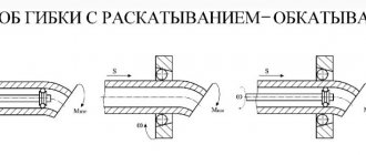
Milling is a type of mechanical processing of materials using a special cutting tool - a milling cutter. The method allows you to obtain a high level of accuracy and the degree of roughness of the processed surface. In addition, it is distinguished by significant productivity.
Surface processing is carried out by the method of up milling, when the rotation of the cutting tool is opposite to the direction of feed, and by down milling - a method in which the direction of rotation of the cutter and feed are identical. By using cutters with cutting edges made from modern super-hard materials, the grinding operation can be replaced.
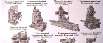
Milling equipment is divided into universal and specialized. In the first case, these are general-purpose machines for performing longitudinal and continuous milling, with or without tools mounted on a console. The second contains a mechanism for cutting threads, splines, making gears and keyways, and pattern milling.
In production, there is often a need to produce several pieces, a batch, or even a series of identical parts. For this purpose, milling equipment equipped with a pantograph is used.
In the household, the functions of a milling machine are usually performed by a manual milling machine. To perform the maximum range of work, the milling cutter is equipped with a whole set of accessories. The main equipment is supplied with the equipment, additional equipment can be purchased or manufactured independently. These are a variety of stops, clamps, templates. But you can go even further and make a copier for milling volumetric parts.
Milling and copying equipment: operating principle
The operating principle of such a device is to clearly transmit the movements of the copy head through the holder profile to the cutting tool.
It is quite difficult to purchase a copy milling machine, so craftsmen make it with their own hands from scrap materials. Everything happens by trial and error. Therefore, experts advise first assembling a duplicate carver, and only then introducing it into mass production. As a rule, this stage is preceded by more than one serious adjustment and alteration.
Classic machine design
The machines are equipped with a sophisticated design system. These include CNC models that operate in an automated mode. Such devices are obtained by using drawings and a copying device. The classic design consists of five nodes:
- The main element is a metal frame; individual parts are connected by welding. The bed has different heights, so when creating a homemade machine, this particular parameter is selected.
- The front and tailstock are needed to store the box, drive and electric motor. The rear one fixes the workpiece to obtain dimensional parts.
- An electric motor and drive rotate the workpiece.
- A tool rest is needed for the best quality work. The cut site is protected to prevent injury.
- The master and slave centers secure the part.
Milling and copying equipment: areas of application
Milling copying machines can process not only flat, but also three-dimensional parts. With their help, along with simple milling operations, you can perform engraving, repeat drawings, patterns and inscriptions. The design of the machine is quite simple, and any craftsman can make it.
Copy-milling machines allow you to process not only wooden parts, but also cast iron, steel and plastic workpieces, as well as products made of non-ferrous metals. This is ensured by high-quality tools made of high-speed steel and hard alloys. The copying machine allows you to mill not only straight, but also curved surfaces. In this case, the details are completely identical.
Design and principle of operation of the machine
A lathe with a copier has the following device:
- Metal frame. It acts as a base to which the main components of turning equipment are attached. The individual elements are attached to the frame by welding.
- Front and rear pillars (headstocks). They house the drive, electric motor and gearbox. The front pillar is mounted on the platform. It houses a mechanism that ensures the transmission of torque from the power unit to the driving center and the workpiece. The tailstock (thrust) moves along the guide and holds the workpiece. The racks must be located on a single axis.
- Faceplate. It is attached to the electric motor pulley. The faceplate has points on which the workpiece is fixed.
- Spindle chuck. Used to hold the workpiece.
- Master and slave centers. They are used to secure a wooden product.
- Tool rest. It is designed to increase processing accuracy.
This type of turning equipment can also be equipped with additional devices:
- Milling attachment. It allows you to cut channels in a spiral shape in both directions and with different pitches.
- Lunette. It acts as a movable support and is used when working with long parts.
- Sanding attachment. This attachment is used for sanding hardwood products.
The following disadvantages of this design are highlighted:
- The working surface must be periodically moved manually. Otherwise it may jam or tilt.
- Using turning equipment, only simple workpieces can be processed.
- An additional helical gear is required to move the cutting tool.
The lathe has the following operating principle:
- The workpiece being processed is fixed to the spindle chuck.
- The workpiece is pressed by a persistent headstock.
- The electric motor turns on, transmitting torque through the drive to the spindle.
- The spindle transmits motion from the drive to the part.
- Cutters cut off unnecessary elements of the workpiece, giving it the required shape.
The edges of the workpiece inserted into the lathe must be folded. This is necessary so that the cutter fits tightly along the wooden surface.
Copier for lathe
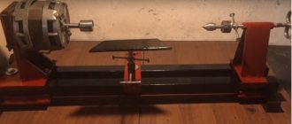
The main element of the copier is a manual router. It is located on a platform made of wood materials with a thickness of 12 mm. Its size is 0.2×0.5 m. The platform contains holes for attaching the cutter and fasteners.
The router should be between the clamps. A separate part of the platform moves along a guide. Its ends are installed on wooden blocks.
Another important element of the copier is a block measuring 7x3 cm. It is fixed in a horizontal position. This element is attached to vertical stands. Templates made of plywood are installed on the block. It is important that the lathe has a thin stop. In this case, it will better copy the template.
If the copier is not used, the block can be dismantled. The platform where the router is located is retracted. To dismantle the copier, you need to unscrew the screws and other fasteners. In this case, the stand where the copier was installed must be tightly fixed.
Milling and copying equipment: design
The typical design of a copy-milling machine is completely simple. It consists of a work table and a guide system with clamps for attaching the router and copier.
Making a universal copy-milling machine at home is quite difficult, and there is no great need for it. For home use, equipment with highly specialized specialization is usually created.
Which is the best wood router?
Now we know enough to choose a horizontal or vertical axis of rotation of the machine spindle. Comparative performance characteristics of horizontal and vertical wood milling machines are summarized in the table:
Horizontal or vertical?
From the data in table. It follows that it makes sense to make a horizontal wood router yourself if you are faced with the need for mass, simple processing of lumber from low-quality raw materials. Not necessarily for sale; perhaps for covering your home with wood siding or clapboard. The savings will be such that it’s time to buy a branded router, but a normal developer doesn’t have extra money. Or, let’s say, still for sale, if you are an individual entrepreneur with a sawmill and a circular saw. Compare market prices for unedged and tongue-and-groove boards, calculate the profitability - is it worth the gamble?
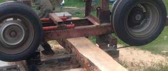
The parts for the most complex module of a horizontal wood router - the spindle assembly - will be made by any skilled turner in a similar way to the same assembly of a circular saw; Structurally, they are the same (see drawings in Fig; sleeve bearings are highlighted in red).
Drawings of a circular saw spindle assembly suitable for a horizontal wood router
The cabinet, dust collector and base plate are the same as for the vertical machine (see below). The plate is even simpler - there is no need for a cutout to mount a vibration-damping motor. The intrinsic vibrations of a horizontal router are an order of magnitude less than those of a vertical router. Transmission from the motor to the spindle further reduces them, and pulleys or sprockets for it can be found in your own trash or at the iron market. An existing circular saw can also be converted into a quite decent horizontal milling machine for wood, see for example. video:
Video: milling machine from a circular saw / jointer
Manufacturing of copy milling machine: materials
To create a duplicate carver at home with your own hands, you should draw a basic sketch, which will become a guide to further actions. In addition, you need to stock up on some materials. This:
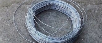
- Knee cemented polished shaft Ø 16 mm.
- Linear bearings in the amount of 2 pcs.
- Rail guides 900 mm long – 2 pcs. For ease of fastening, their length is taken as a multiple of 150.
- Split linear bearings in the amount of 4 pcs. It is advisable to use bearings with a clamping screw to adjust the tightness of the fit on the guide.
- Profile pipe 30×60 with a wall thickness of up to 3 mm.
- Metal plate 900 mm long and 100 mm wide.
- End posts in the amount of 2 pcs.
- Moving element in the form of a plate – 1 pc.
- Rocker arm for attaching the copier and router – 2 pcs. The length is chosen arbitrarily.
- Movable couplings – 2 pcs.
- Profile pipe 40×40 with a wall thickness of up to 3 mm.
- Crown clutch for turning the part and template.
How to use such a device for a router?
The stencil is applied to the workpiece according to the markings and fixed. A hole is made with a drill. A cutter is inserted into it and the contour is processed.
Reference! When working with a milling cutter with cutting edges along the end, depth limiters are set on the router guides and the drill is not used.
In everyday life, groove milling using a copy sleeve is most often used when installing doors. Craftsmen cut out grooves for handles and locks on site with high precision, and make lowerings for canopy slats.
Important!
The copying sleeve allows you to make grooves of different widths with one cutter of a smaller diameter in 2 passes.
In carpentry workshops, decorative furniture elements are cut out using a template. Using shaped cutters, a carpenter produces batches of parts with complex patterns. The copying sleeve makes it accessible and simple to select grooves and recesses of any configuration. It is enough to make the template correctly and adjust the processing depth.
Making a copy-milling machine: tools
After this, you need to prepare a tool that will definitely be useful for assembling the machine structure. This:
- angle grinder;
- cutting and cleaning disc;
- welding machine;
- welding mask;
- petal disc or brush;
- self-tapping screws for fastening rail guides and moving elements;
- electric drill;
- screwdriver;
- measuring instruments: tape measure, caliper;
- center punch and scriber.
Making a copy-milling machine: step-by-step instructions
After everything is ready, the actual assembly of the copy-milling machine begins.
Step #1
It is necessary to cut two pieces 950 mm long from a 30×60 profile pipe to attach the rail guides. A margin of 50 mm is needed for installing limit switches in order to prevent linear bearings from slipping off.
Step #2
The 40×40 profile pipe needs to be cut into blanks for the base. Guided by the existing sketch, you need to cut two pieces of 1350 mm and two pieces of 900 mm.
Step #3
It is necessary to cut small racks from the same pipe. Their linear size depends on the height of the subsequently processed parts.
Step #4
Now you need to remove the rust from the pipes.
To do this, you can use a flap disc or brush. Important ! Before using the brush, pay attention to the maximum number of working revolutions on it and the grinder. The rotation speed on the brush must exceed the speed of the equipment.
Step #5
After this, we weld all the joints and clean the seams with a 6 mm thick cleaning wheel.
Step #6
Then it is necessary to ensure parallelism of the rail guides. To do this, you need to make the connection between the rack and the base of the rail guide detachable. It is necessary to take a washer according to the internal size of the rack, weld a nut to it and screw in the bolt. At this stage, the bolt is needed in order to install the nut and washer in the cavity of the stand pipe flush and in a strictly vertical position, and when welding it, do not damage the thread. This must be done with all four racks.
Step #7
Weld the posts to the base.
Step #8
At the base of the rail guide, at the junction with the racks, you need to drill holes: in the upper shelf for the bolt head, in the lower one for the thread.
Step #9
Install the rail guides on the base (30×60 pipe), pre-drilling holes, and secure with metal screws.
Step #10
Install the bases with rail guides and tighten with bolts.
Step #11
Check the parallelism of the guides. If it is missing, it is necessary to make adjustments by placing foil of different thicknesses on the racks under the guide.
Step #12
On the metal plate you need to mark and drill holes for attaching split linear bearings and end posts.
Step #13
After this, you need to make a movable element by welding 300 mm long rocker arms for the feeler gauge and router to a metal plate, then attach linear bearings to it.
Step #14
After this, the moving element must be placed on a polished shaft, along the edges of which the end posts must be installed.
Step #15
The entire structure must be installed on a metal plate 100 mm wide and the end posts must be secured with self-tapping screws.
Step #16
Then, split linear bearings must be installed on the metal plate on the bottom side.
Step #17
After this, the suspended structure is put on the rail guides with split bearings and the end switches are installed.
Step #18
Movable couplings are installed at the end of the rocker arms and a probe and a milling cutter are attached.
Step #19
In order for the workpiece and the part to rotate synchronously, it is necessary to connect them with couplings. A sprocket and crown are suitable for control. The copy milling machine is ready. The design achieved 5 degrees of freedom. Movement along the X axis is ensured by the movement of the structure along rail guides, movement along the Y axis is ensured by the movement of a moving element along a polished shaft, and movement along the Z axis is ensured by the movement of rocker arms.
Additionally, due to the movable couplings, the probe and the milling cutter can move left and right along the axis of the rocker arm, and it is possible to move the template and the workpiece simultaneously. This makes it possible to process parts of almost any shape.
Making it vertical
A vertical wood milling machine has much greater functionality and provides better quality of material processing than a horizontal one. It is vertical milling machines that are mostly built by home-made amateurs. However, the problem of combating vibrations in a vertical milling machine is much more acute. If in a horizontal router vibrations through the base of the spindle unit are given priority. down and are effectively damped, being reflected in the thickness of the material, then in a vertical machine, elastic waves in the machine plate propagate mainly to the sides. In this case, their inerference is possible and the emergence of standing waves with antinodes (foci) of such a size that the workpiece is thrown away from the cutter. Therefore, one of the main tasks of designing a homemade vertical router is to suppress machine vibrations.
Structural diagram
Vertical milling machines with a bottom drive of a free (fixed only from below) cutter are least susceptible to vibration. The working body is mounted directly on the motor shaft. The entire drive is made as vibration-resistant as possible. Under the influence of the beating of the cutter on irregularities in the workpiece, the drive staggers and sways. At the same time, a noticeable transverse (vertical) component appears in the waves of elasticity, effectively absorbed by the frame, and a heavy motor with a massive, rapidly rotating rotor plays the role of an inertial absorber of mechanical vibrations.
The structure of industrial and homemade vertical wood milling machines is shown in the figure:
Construction of industrial and homemade vertical milling machines for wood with bottom drive
Their main difference is in the folding (lifting) stop 7. Since amateur designs do not use drives of 5 kW or more with high-performance cutters, the folding stop is replaced by a lifting one, which prevents the workpiece from being squeezed upward from the cutter. Also, for an amateur machine, an adapter attachment with a Morse taper on the motor shaft is machined to order, the same as for a homemade drilling machine. A standard clamping chuck for a cylindrical shank is installed on the cone. In this design, it is also possible to use mounted cutters: adapters for them with a cylindrical shank are commercially available or are included in the set of cutters. The most important structural components of such a machine are:
- The base plate is the main damper of longitudinal (horizontal) elastic waves in the machine;
- Vibration damping drive board;
- Comb stops (stop) – dampen vertical vibrations of the workpiece;
- Static side stop - ensures correct feeding of the workpiece, and in a homemade machine also some adjustment of the cutter output (horizontal processing depth);
- Dust collector – removes processing waste to the dust collector.
The latter is absolutely necessary when milling, because The cutter produces several times more wood dust, sawdust and shavings than is produced during sawing. The base plate is most often made integral with the vibration damping suspension of the drive. The cabinet (bed) can be anything, as long as the slab and other parts do not fall down.
Drive plate and suspension
Installing the drive of a homemade wood milling machine into the base plate
The window (opening) for hanging the drive from the machine plate is most often cut out square (see figure on the right), this is easier at home. But the machine will tremble much less during operation if the window for the drive is made round. In any case, the motor should not directly touch the plate (again, see the figure on the right), otherwise, instead of dampening vibrations, they will be amplified.
The best materials for the plate and drive board are fiber-laminated plastics: textolite, fiberglass with a thickness of 12-15 mm; the thicker the better. Hardboard and other massive plastics are less suitable: they dampen vibrations well, but over time they warp when heated by the motor and the machine loses accuracy. Getinax and other thermosetting laminates are unsuitable: they delaminate very quickly due to vibrations.
However, it is neither possible nor practical to make the entire slab as one piece: it is difficult, expensive, and the vibrations of the drive itself will be freely transmitted to the slab. You only need to make the motor board from plastic, and the slab from plywood impregnated with a vibration-absorbing composition and glued together, and low-grade construction and packaging material will do. The slab must be re-glued with at least 5 sheets so that the fibers of the outer layers of adjacent layers are oriented mutually perpendicular.
The cutting diagram for a standard sheet of plywood 1550x1550x4 mm into sheets for the base plate of a wood milling machine is given on the left in Fig. Sheets for the horizontal router plate are cut out without windows for the motor, but with a dust collector socket (see above and below). Slab size up to 750x500 mm. A 50 mm flash along the contour of the sheet is needed to cut off low-quality material at the edges.
Scheme for cutting a sheet of plywood and a device for suspending the drive of a homemade wood milling machine
The sheet is first generously impregnated 2-3 times on each side with eco-construction soil (water-polymer emulsion), it perfectly dampens vibrations. The interval between impregnations is at least 3.5 hours. Then the sheet is cut out and a plastic film is spread on the floor (not PVC, it will stick!). Sheet No. 1 is placed on the film and with a brush (preferably a “shaggy” paint roller) a thin, even layer of mounting (reinforced) PVA is applied to it; the same layer is placed on the adjacent side of sheet No. 2. Immediately after applying the glue, the brush (roller and its tray) are thrown into a bucket of water, and after all gluing is completed, they are washed in water.
Before folding, the sheets are kept for 15-20 minutes (or according to the instructions on the glue package), folded and straightened, without being separated, so that the edges of the drive window meet exactly. Then sheets No. 3, 4 and 5 are glued in the same way. The entire package is covered with film and loaded over the entire area with a dispersed load of 30-40 kg (it is best to pile on more books or magazine files). Dry for at least 3 days at room temperature: mounting PVA is durable, its adhesive layer is viscous and perfectly absorbs vibrations, but takes a long time to dry to full strength.
The design of the motor suspension is shown in the section on the right in Fig. A gap of 0.5-1 mm should be left between the motor board and the machine plate. There is no need to clean sawdust out of it: it will serve as an additional side vibration-damping cushion. It is advisable to find a motor with mounting feet that protrude beyond the dimensions of the housing: then it will be possible to install (not quickly) the extension of the cutter upwards. To set the cutter in height, the motor mounting screws are taken long, and the stem itself is set by putting steel washers on them, between the rubber suspension cushion and the motor body, alternately with gaskets made from the same tube-type truck tire.
The slab with the hanger is checked for workmanship with a pencil. If you place it sticking out 5 cm from the edge of the suspension board, then when the engine is on at idle, the pencil should not fall.
Stop and dust collector
For a drawing of a simple but good static side stop with a dust collector socket, see the following. rice. The material is re-glued plywood from the same sheet. Holes for the comb and lifting stops are drilled in 3-5 pieces: the first 50 mm from the edges of the cutout for the cutter (rectangular); the rest after 25-30 mm. The position of the stops is selected depending on the size of the workpiece and the quality of its material. The lateral offset of the cutter is adjusted within small limits by turning the stop and securing it with a clamp.
Drawing of a side support with a dust collector for a homemade wood milling machine
Dust collector
Dust collector device for a homemade wood milling machine
Since there is no industrial pneumatic system with air extraction at home, milling dust has to be sucked out with a household vacuum cleaner. If you connect it directly to the dust collector pipe, the required expensive household appliance will soon fail. An expensive, well-cleaning vacuum cleaner with a hydraulic separator will most likely immediately. So, in addition to a dust collector, a homemade wood router also requires a dust collector, through which the vacuum cleaner is connected.
The design of a dust collector for a milling machine is shown in Fig. on right. The container is round, from 10-15 l (preferably from 20 l). The ideal option is a household bucket with a tight lid, fitted with a seal and equipped with snap-on latches (both can be done with your own hands).
Inlet pipe – diameter approx. 20 mm (inside). Its end is beveled 45 degrees and rotated 20-30 degrees outward; installed 15-20 mm from the side of the vessel (counting from the outer edge of the pipe). The exhaust pipe is wider, approx. 30 mm inside; is installed exactly along the vertical axis of the container. Its selected end is narrowed to 15-20 mm (the taper is not critical). Everything works together like a cyclone, and the air entering the vacuum cleaner is clean enough not to spoil the device.
Note: an additional advantage of the dust collector is that the dust from it is an excellent filler for high-quality wood putty. For this, the dust is mixed with PVA (3-4):1 by volume.
Comb
A drawing of the comb stop of a wood milling machine is given in the following. rice. Material – hard elastic fine-grained wood (oak, beech, walnut) without defects – strands, rot, cross-layers, knots – 20 mm thick. A pair of combs is needed, right and left, so that the workpiece can be fed from either side.
Drawing of a comb stop for a homemade wood milling machine
The first comb tooth along the workpiece (pay attention!) is shortened by 3 mm. It does not directly contact the workpiece, but serves as a rebound spring for the entire comb. Without it, the comb may get caught in the workpiece and break.
Fastening the combs to the side stop - with a bolt with a wing nut through a longitudinal groove (slotted hole in the figure); fixing the non-working one with a self-tapping screw to the same stop through hole D7. The comb is placed in the working position so that it touches the workpiece with all teeth except the first, and is fixed with a thumb.
Pantograph for a router: principle of operation
The schematic diagram of a pantograph looks quite simple. It is a square divided in half. All joints are hinged, so all sides are movable, and the square easily turns into a rhombus when impacted. The zero point, located in one of the corners of the square, is fixed rigidly. Relatively, its design can be modified, turning into a rhombus. A cutting tool is installed in the middle of the square. A copier is fixed diagonally in the opposite corner of the square. The distance from the zero point to the cutter is a certain value A, and to the copier 2A. This gives a 2:1 scale. The linear size of the long and short sides of the pantograph should also differ from each other by 2 times.
Copier for lathe
guide pipe
The basis of the copier will be an unnecessary manual router. It is placed on a surface made of 12 mm plywood, the size of the platform is 20 x 50 cm. Holes are made in the platform for fasteners and cutters, and stops are installed - bars for fixing the cutter. The router is placed between the clamps and secured with a pair of large nails.
The remote part of the platform moves along the frame along a guide - a pipe. Its ends are fixed in wooden blocks. The bars are attached to the frame with self-tapping screws. When fixing the pipe, you must use a level and align the axis of the pipe with the center of the machine. Before installation, a pair of bars with holes are put on the pipe and can be easily moved along the guide. A platform on which the router is placed is attached to the bars.
stop-copier
The second important element is installed with your own hands directly on the lathe - a block in a horizontal position on which the templates will be attached. A 7 x 3 cm beam is suitable; it is attached to the vertical stands with self-tapping screws. The stands are screwed to the frame. The top surface of the block must clearly coincide with the axis of the machine.
When the copier is not in use, the block is dismantled, the platform with the milling cutter is moved back and the machine turns into a regular lathe.
The stop is made of thick plywood and is attached to the work surface. In fact, the stop plays the role of a copier in this design. It is fixed vertically and fixed to the end of the working surface on a transition beam made of wood. The copier can be removed, it is installed on the stand with self-tapping screws. The stand must be fixed firmly, without the possibility of removal.
The templates are made of plywood and are screwed to the front surface of the block using self-tapping screws. The upper surface of the beam should be aligned with the axis of the template.
Pantograph for a router: materials
In order to make a pantograph with your own hands, you will need the following materials:
- Square metal profile 12×12
- Bearing 180201.
- Bushings for the outer race of the bearing.
- Pins according to the internal size of the bearing and M12 thread.
- Nut M12.
- Bolts M6×45
- Nuts M6.
- Bushing for securing the copier.
- Profile pipe 40×40
- Hinge of a metal-plastic window.
- Dye.
- Masking tape.
- Metal plate.
- Screw for fixing the copier.
Pantograph for a router: step-by-step instructions for making it yourself
Let's proceed to the actual production of the pantograph.
Stage No. 1. Workpiece cutting
It is necessary to mark and cut the square profile according to the calculated dimensions. For convenience, you can use masking tape and a metal plate. The tape will allow for clear markings, and the plate will help make an even and high-quality cut. The blanks for the platform for the router must be cut at a right angle, and the sections of the profile for the connecting rods must be beveled for maximum fit of the bearing sleeve.
Stage No. 2. Drilling technological holes
All workpieces must be chamfered and holes Ø 6.2 mm drilled for further connection into the structure.
Stage No. 3. Welding the platform for the router
After this, you need to weld the platform for the router.
Stage No. 4. Manufacturing of connecting rods
It is necessary to make something like a jig on the board and firmly fasten all the parts to be welded. To do this, a hole is drilled in the board, and the bearing in the bushing is clamped with a bolt, the square profiles of the connecting rods are secured with clamps. First you need to insert two washers between them and fasten them with bolts. After this, all joints of the structure are scalded and cleaned. Then you need to cut the bearing sleeve between the square profiles on each connecting rod. M6 bolts, washers and bearings must be removed. It is necessary to weld a mount for the router onto the frame, and an extension for scaling onto the short connecting rod at the point opposite the zero point. The connecting rods can be painted to give an aesthetic appearance.
Stage No. 5. Making a unit for attaching a copier
Now you need to machine two bushings with an internal diameter similar to the size of the copier. Drill a hole on the side and cut a thread to install the screw that secures the copier. After this, you need to cut two pieces of 12x12 squares 20-30 mm long and weld them on the side between the bushings. The size between squares should be 12 mm.
Stage No. 6. Manufacturing of the bearing lifting mechanism
It is necessary to manufacture a bearing lifting unit. To do this, the zero point finger must be welded onto a piece of 12×12 profile and secured to a 40×40 profile pipe using a loop from a metal-plastic window. The profile pipe will serve as a place for attaching the pantograph to the table with a clamp.
Stage No. 7. Pantograph assembly
The bearings must be installed in the bushings and secured securely by tightening the square profiles of the connecting rods with M6 bolts. Using your fingers, you need to assemble the connecting rods into a single structure. Secure the pantograph to the table with a clamp and install the router. The device is ready for use.
Features of the production of devices
Before making a template, it is necessary to know exactly the diameters of the cutting tool and fixture. The template should protrude outside the specified sample contour by a size equal to the difference in the radii of the sleeve and cutter. Its thickness is allowed from 2 mm to 10 mm. You can make a stencil using simple tools.
- Draw the outline of the groove on the sheet of the future template.
- Subtract the difference in the diameters of the sleeve and cutter.
- Draw a parallel line outside the contour to be cut, retreating the calculated size.
- Cut the stencil along the outer line.
Clean off burrs and sharp edges. Now it is enough to secure the template on the surface to be treated with clamps, and you can cut out the grooves.
Important!
The contact line of the sleeve with the end of the template is equal to the thickness of the sheet with which it is made. Contact voltages are small. This allows you to make devices from soft materials: plywood, plastic, plexiglass. When producing large batches of parts, it is more practical to make a stencil from steel.