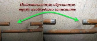
To cut internal threads with a magnetic drilling machine, you will need tools such as a tap and a threading chuck with the necessary safety heads, which are usually included in the threading kit. If you don't have a threading kit, you can use a direct adapter from the tap to the Weldon, but in this case there is a risk of tool breakage. Also, immediately before the cutting process, it is necessary to pre-drill a hole in the part of the appropriate diameter.
A tap is a special tool for cutting internal metric threads in through and blind holes. As a rule, taps come in sets of two: one rough - for initial threading, the other finishing - for finishing the hole. The difference between one tap and another is that the cutting surface of the rough tap is not as pronounced as the finishing one.
| Roughing and finishing taps |
Important! Taps must be made of quality material! A cheap Chinese tool will quickly have a dull cutting edge and will not be able to cut threads. The tap will simply get stuck in the material, because... the safety mechanism in the safety insert will operate. Removing it will be much more problematic than buying a new tool.
Threading chuck and safety insertsTo cut threads you will need a thread cutting set. The thread-cutting chuck is used in magnetic drilling machines both with and without spindle rotation reversal. The difference is that a magnetic drill press with reverse provides a switch from right rotation to left rotation, which allows you to conveniently move the tap back out of the hole without removing it from the chuck. | Threading set M12-M24 with safety inserts |
What diameter should I use for the hole in which we will cut the thread?
We select the appropriate drill diameter depending on the thread diameter and its pitch . Recommended hole diameters are given at the end of the article.
How to cut threads by hand correctly and without wasting a tool
The technological process of thread cutting is divided into several operations.
- Preparation. Using the correspondence table, select a drill of the required diameter and accurately drill the hole, preventing the drill from slipping. The drill must be sharpened correctly, otherwise the material will overheat and the thread strength will decrease. Countersink the hole. In case of a blind hole, give an allowance for depth.
- To cut threads, use taps of standard sizes only.
- Slicing. Movements should be neat and measured. Do not skip numbers; all three should be used sequentially - from rough to final.
- After each full turn, the driver should be given a half turn in the opposite direction to chip the chips and push them out of the grooves.
- Cleaning. Pass-through holes are cleaned with a wire brush, blind holes are cleaned with an industrial vacuum cleaner or a stream of compressed air.
- Examination. Screw the screw into the hole. It should fit in without distortion and follow the thread smoothly and effortlessly.
Sequence of thread cutting with a tap
There are other secrets of hand-cutting in folklore, but to obtain high-quality carving it is enough to strictly follow the above
Cutting internal threads with a magnetic drilling machine
To cut internal threads with a magnetic drilling machine, you will need tools such as a tap and a threading chuck with the necessary safety heads, which are usually included in the threading kit. If you don't have a threading kit, you can use a direct adapter from the tap to the Weldon, but in this case there is a risk of tool breakage. Also, immediately before the cutting process, it is necessary to pre-drill a hole in the part of the appropriate diameter.
A tap is a special tool for cutting internal metric threads in through and blind holes. As a rule, taps come in sets of two: one rough - for initial threading, the other finishing - for finishing the hole. The difference between one tap and another is that the cutting surface of the rough tap is not as pronounced as the finishing one.
| Roughing and finishing taps |
Important! Taps must be made of quality material! A cheap Chinese tool will quickly have a dull cutting edge and will not be able to cut threads. The tap will simply get stuck in the material, because... the safety mechanism in the safety insert will operate
Removing it will be much more problematic than buying a new tool.
the safety mechanism in the safety insert will operate. Removing it will be much more problematic than buying a new tool.
Threading chuck and safety insertsTo cut threads you will need a thread cutting set. This set includes a thread-cutting chuck with a Morse taper shank and a set of quick-change inserts (bushings) for installing taps. The chuck has overload protection and axial thread pitch compensation systems. The inserts have a torque adjustment mechanism, which allows you to prevent tool breakage (as the torque increases, the tap stops), as well as to produce high-quality threads. The inserts have a convenient mechanism for quickly changing the tap, ensuring its reliable fixation. The thread-cutting chuck is used in magnetic drilling machines both with and without spindle rotation reversal. The difference is that a magnetic drill press with reverse provides a switch from right rotation to left rotation, which allows you to conveniently move the tap back out of the hole without removing it from the chuck. | Threading set M12-M24 with safety inserts |
What diameter should I use for the hole in which we will cut the thread?
We select the appropriate drill diameter depending on the thread diameter and its pitch. Recommended hole diameters are given at the end of the article.
Threading process
For blind threads, you need to turn on the right rotation and “sink” the tap into the hole, after it stops, switch the direction of rotation to the left and the tap will smoothly come out back along its thread. It is impossible to make such a thread without reverse.
For through threads with right rotation, we pass the tap all the way down in the desired part, and then, by switching to left rotation, we move slowly upward. For through threads on magnetic drill presses without reversing, once the tap has passed, it will need to be removed manually before proceeding.
Recommendations for the thread cutting process
Threading must be done at low speed. In this case, you cannot make sudden movements; the tap must move very smoothly!
Be sure to liberally use lubricating coolant (coolant concentrate) in magnetic drilling machines with an integrated supply system, or lubricate it externally with special wax, paste or foam.
Principle of operation
Safety heads, which are used when operating a drilling machine, consist of the following elements: a metal body, a driver, a bushing, several balls, a disc spring and a regular spring, a nut, a sleeve, a washer, and a locking ring.
All components make it possible to create a safety structure to protect the cutting tool from the strong impact of rotating force.
The operating principle is as follows:
- There is a special socket for the tap, which has a square shape. The socket is represented by a hole in the body and a special bushing.
- Clamping of the cutting tool occurs due to the balls and the movement of the sleeve under the action of a spring.
- The main movement, axial, transmits torque to the body through balls and a driver, which are pressed by disc springs and a ring.
- A special nut changes the deformation rate of the disc springs, which causes a change in the transmitted torque.
Classification of threads
A thread is a helical line formed on the surface of a body of revolution by the top of a protrusion of a certain shape. The distance between adjacent protrusions is equal to the thread pitch. The shape of the protrusion depends on its type. Between two adjacent protrusions there is a depression.
Classification of threads
Types of threaded features:
- Helix direction:
- right (it rises from left to right, and the bolt is screwed in a clockwise direction);
- left (screwing occurs counterclockwise).
- Protrusion shapes in the form:
- triangle,
- trapezoids,
- unequal trapezoid,
- rectangle,
- semicircle.
- The outer surface of the part (cylindrical or conical).
- Location on the part (internal or external).
- Number of visits (one, two, three);
- Purpose (fastening and chassis).
Threads are divided into types:
- with profile angle: 60⁰ (metric, conical inch);
- 55⁰ (cylindrical pipe, conical pipe);
Trapezoidal threads have greater strength than rectangular threads, while being less labor-intensive to manufacture. The purpose of a trapezoidal thread is to convert rotational motion into translational motion.
In addition, they use a thread called modular. It is used where rotation is transmitted from a worm to a worm wheel, the axes of which are at an angle of 90⁰.
Decoding the writing of threads
The thread is designated: M12x1.25–7N. This means: metric internal (7H), diameter 12 mm, pitch - 1.25 mm, tolerance range 7H. For external threads, the tolerance field is written: 6h. The coarse pitch value is not given in the designation (M16–8g). The letters LH (M16–8g–LH) are added to the left-hand thread in the designation. GOST 8724–81 provides a table indicating the diameter and pitch of the required size.
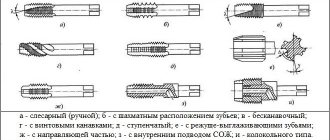
Types and areas of application of taps
Internal thread cutting can be done manually or using various types of machines (drilling, lathe, etc.). The working tools that perform the main work of cutting internal threads are machine-hand or machine taps.
Taps are divided into different types depending on a number of parameters. The following principles for classifying taps are generally accepted.
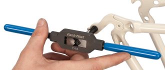
- According to the method of rotation, a distinction is made between machine-manual and machine taps, with the help of which internal threads are cut. Machine-hand taps equipped with a square shank are used in conjunction with a special device with two handles (this is the so-called tap holder). With the help of such a device, the tap is rotated and cuts the thread. Thread cutting with a machine tap is carried out on metal-cutting machines of various types, in the chuck of which such a tool is fixed.
- Based on the method by which internal threads are cut, a distinction is made between universal (through) taps and complete taps. The working part of the former is divided into several sections, each of which differs from the others in its geometric parameters. The section of the working part that first begins to interact with the surface being processed performs rough processing, the second - intermediate, and the third, located closer to the shank - finishing. Cutting threads with complete taps requires the use of several tools. So, if a set consists of three taps, then the first of them is intended for roughing, the second for intermediate, and the third for finishing. As a rule, a set of taps for cutting threads of a certain diameter includes three tools, but in some cases, when products made of particularly hard material are processed, sets consisting of five tools can be used.
- Based on the type of hole on the inner surface of which it is necessary to cut a thread, taps for through and blind holes are distinguished. A tool for processing through holes is characterized by an elongated conical tip (approach), which smoothly passes into the working part. Universal type taps most often have this design. The process of cutting internal threads in blind holes is carried out using taps, the conical tip of which is cut off and performs the function of a simple milling cutter. This design of the tap allows it to cut threads to the full depth of a blind hole. To cut a thread of this type, as a rule, a set of taps is used, driven manually using a wrench.
- According to the design of the working part, taps can have straight, helical or shortened chip removal grooves. It should be borne in mind that taps with grooves of various types can be used for cutting threads in products made of relatively soft materials - carbon, low-alloy steel alloys, etc. If threads need to be cut in parts made of very hard or viscous materials (stainless, heat-resistant steels, etc.), then for these purposes taps are used, the cutting elements of which are arranged in a checkerboard pattern.
A good tap is made of high-quality tool steel, looks neat and has smoothly machined turns and grooves
Taps are usually used for cutting metric threads, but there are tools that can be used to cut pipe and inch internal threads. In addition, taps also differ in the shape of their working surface, which can be cylindrical or conical.
Lecture No. 11.2 Processing parts on drilling machines.
Drilling machines are designed for drilling holes, cutting threads into them with a tap, boring and lapping holes, cutting disks from sheet material, etc. These operations are performed with drills, countersinks, reamers and other similar tools.
There are the following types of universal drilling machines.
1. Single-spindle tabletop drilling machines are used for machining small-diameter holes. The machines are widely used in instrument making. The spindles of these machines rotate at high speed.
2. Vertical drilling machines (the main and most common type) are used primarily for processing holes in relatively small parts. To align the axes of the hole being machined and the tool, these machines provide for the movement of the workpiece relative to the tool.
3. Radial drilling machines used for drilling holes in large parts. On radial drilling machines, alignment of the axes of the holes and the tool is achieved by moving the machine spindle relative to the stationary part.
4.Multi-spindle drilling machines, which provide a significant increase in productivity compared to single-spindle machines.
5. Horizontal drilling machines for deep drilling.
The group of drilling machines also includes centering machines, which are used to produce center holes at the ends of workpieces.
The main dimensions of drilling machines are: the largest nominal drilling diameter, the size of the spindle cone, the spindle overhang, the largest spindle stroke, the largest distances from the end of the spindle to the table and to the foundation plate, etc.
Drilling machines are used to create blind as well as through holes in solid materials. Also used for finishing holes that were made using another method. In addition, drilling machines are used for:
· drilling holes (to ensure high accuracy and roughness of the hole in the workpiece);
· cutting out discs;
· performing operations such as cutting out disks using countersinks, drills, reamers, taps, etc.;
· cutting internal threads;
· countersinking of end surfaces;
· rolling out holes using mandrels.
Drilling machines are also used to produce sockets in the base that already have holes, which have a flat bottom, for the heads of bolts and screws. But the scope of use of drilling machines is actually much wider than the range of the listed operations. They are also used for processing holes with a large number of edges and for flaring hollow rivets.
Hole parameters
The following thread parameters are distinguished:
- diameters (internal, external, etc.);
- profile shape, height and angle;
- step and entry;
- others.
The condition for connecting parts to each other is the complete coincidence of the external and internal threads. If any of them are not performed in accordance with the requirements, the fastening will be unreliable.
External thread
The fastening can be bolted or stud, which, in addition to the main parts, includes nuts and washers. Before joining, holes are formed in the parts to be fastened, and then cutting is carried out.
When performing a through design, the diameter of the hole must be 5-10% larger than the size of the bolt or stud, then the following condition is met:
dresponse = (1.05..1.10)×d, (1),
where d is the nominal diameter of the bolt or stud, mm.
To determine the hole size of the second part, the calculation is carried out as follows: the pitch value (P) is subtracted from the value of the nominal diameter (d) - the resulting result is the desired value:
dresponse = d - P, (2).
The calculation results are clearly demonstrated by the table of threaded hole diameters, compiled according to GOST 19257-73, for sizes 1-1.8 mm with small and main pitches.
| Nominal diameter, mm | Pitch, mm | Hole size, mm |
| 1 | 0,2 | 0,8 |
| 1 | 0,25 | 0,75 |
| 1,1 | 0,2 | 0,9 |
| 1,1 | 0,25 | 0,85 |
| 1,2 | 0,2 | 1 |
| 1,2 | 0,25 | 0,95 |
| 1,4 | 0,2 | 1,2 |
| 1,4 | 0,3 | 1,1 |
| 1,6 | 0,2 | 1,4 |
| 1,6 | 0,35 | 1,25 |
| 1,8 | 0,2 | 1,6 |
| 1,8 | 0,35 | 1,45 |
An important parameter is the drilling depth, which is calculated from the sum of the following indicators:
- screw-in depth;
- reserve of external thread of the screwed-in part;
- her undercut;
- chamfers.
In this case, the last 3 parameters are for reference, and the first is calculated through the coefficients for taking into account the material of the product, which are equal for products from:
- steel, brass, bronze, titanium – 1;
- gray and ductile cast iron – 1.25;
- light alloys – 2.
Internal thread on barrel coupling
Thus, the screw-in depth is the product of the material factor and the nominal diameter, and is expressed in millimeters.
This is interesting: Wire bending: manually and on wire bending machines
Homemade tap for aluminum alloys
To create internal threads in brass or light alloy parts, you can use homemade tools and drills from a regular set. Calibrated steel wire will do. Using a die, an external thread is cut on it, after which the workpiece is hardened. After hardening, it is necessary to release the part to the color of ripe straw. The cutting edges are sharpened using a whetstone or sharpener, after first clamping the part into a collet chuck.
Video on how internal threads are cut:
HOLES FOR TAPERED PIPE THREAD
DIAMETERS
GOST 21350-75
STATE COMMITTEE OF STANDARDS OF THE COUNCIL OF MINISTERS OF THE USSR
Moscow
DEVELOPED, INTRODUCED AND PREPARED FOR APPROVAL by the All-Union Scientific Research Institute for Normalization in Mechanical Engineering (VNIINMASH)
And about. Director Gerasimov N.N.
Topic leader and performer Zaroslova M.P.
APPROVED AND ENTERED INTO EFFECT by Resolution of the State Committee of Standards of the Council of Ministers of the USSR dated December 12, 1975 No. 3877
STATE STANDARD OF THE USSR UNION
| HOLES FOR TAPERED PIPE THREAD Diameters Holes for threading pipe taper screw thread. Diameters | GOST 21350-75 Instead of MN 5389-64 |
By Decree of the State Committee of Standards of the Council of Ministers of the USSR dated December 12, 1975 No. 3877, the validity period was established
from 01.01.77
1. This standard establishes the diameters of holes for cutting conical pipe threads in accordance with GOST 6211-69 in steel products in accordance with GOST 380-71, GOST 4543-71, GOST 1050-74, GOST 5058-75 and GOST 5632-72 (except for alloys on nickel base) and copper according to GOST 859-66.
2. The diameters of the holes with reaming to a cone and their maximum deviations must correspond to those indicated in the drawing. 1 and in table. 1.
Table 1
Dimensions in mm
| Number of threads per 1² | Step P | Hole diameter | Drilling depth l | d c | d o | Nom. | Prev. off | Nom. | Prev. off | 0,907 | 8,10 | 0,20 | 8,57 | 0,10 | 1,337 | 10,80 | 0,24 | 11,45 | 14,30 | 14,95 | 1,814 | 17,90 | 18,63 | 23,35 | 0,28 | 24,12 | 2,309 | 29,35 | 30,29 | 1 1/4 | 37,80 | 0,34 | 38,95 | 1 1/2 | 43,70 | 44,85 | 55,25 | 0,40 | 56,66 |
Note. For threads with nominal size above 2 ² nominal hole diameters d
o and their maximum deviations must be equal to those established by GOST 6211-69 for the internal diameter of the thread.
3. The diameters of the holes without turning to a cone and their maximum deviations must correspond to those indicated in the drawing. 2 and in table. 2.
4. It is allowed to use holes of other diameters obtained on the basis of experimental data for cutting conical pipe threads.
5. The diameters of drills for holes for tapping are indicated in the recommended one.
table 2
Dimensions in mm
| Nominal thread size in inches | Number of threads per 1² | Step P | Hole diameter d c | Drilling depth l | Nom. | Prev. off | 1 / 8 | 0,907 | 8,25 | 0,20 | 1 / 4 | 1,337 | 11,05 | 0,24 | 3 / 8 | 14,50 | 1 / 2 | 1,814 | 18,10 | 0,28 | 3 / 4 | 23,60 | 2,309 | 29,65 | 1 1 / 4 | 38,30 | 0,34 | 1 1 /2 | 44,20 | 56,00 | 0,40 | Diameters of drills for holes for cutting conical pipe threads Dimensions in mm Nominal thread size in inches | Number of threads per 1² | Step P | Drill diameter for hole | with cone deployment | without cone deployment | 1 / 8 | 0,907 | 1 / 4 | 1,337 | 10,8 | 11,1 | 3 / 8 | 14,25 | 14,5 | 1 / 2 | 1,814 | 3 / 4 | 23,25 | 2,309 | 1 1 / 4 | 38,25 | 1 1 /2 | 56,00 |
To cut an internal thread on a part, you must first drill a hole. Its size is not equal to the thread diameter, but should be slightly smaller. You can find the diameter of the drill for the thread in a special table, but to do this you also need to know the type of thread.
Recommendations for machine thread cutting
- In workpieces produced by casting or forging, holes must be pre-drilled or countersinked, because there is no possibility to make them for threading within the tolerance.
- Cut a chamfer from the tap supply side at an angle of 60 and a depth of more than 1 thread pitch.
- Use specialized thread-cutting drill chucks: reversible, floating, oscillating, self-centering, safety.
- To eliminate scoring, torn turns and increase tool life, use pastes and lubricants.
Coolant to improve cutting properties and heat removal can be made independently at home. The simplest recipe is the version developed by G.D. Petrov. The lubricant contains:
- oleic acid - 78%;
- stearic acid - 17%;
- finely ground sulfur – 5%.
Heat oleic and stearic acids to a temperature of 65 C and mix. When the solution has cooled to a temperature of 20 C, it is necessary to mix it with sulfur.
When processing light alloys, you can use kerosene or a 10% fatty emulsion as a coolant.
Pay attention to the nuances when cutting blind holes on a drilling machine: you must first drill holes longer than the length of the thread itself, if this is structurally possible. This event promotes chip removal and the formation of a full profile; use safety chucks: when the tool hits the bottom, it will automatically stop rotating and will not break; if your machine does not have a spindle reversal, then use reversible chucks to unscrew the tap. Working on a magnetic drilling machine
Working with a magnetic drilling machine
To avoid defects when cutting threads on a drilling machine, adhere to the following rules:
- prepare the diameter according to GOST;
- choose the right tool of the required design and geometry according to the material being processed;
- remember that taps can be made in sets: rough and finishing, therefore, it is imperative to use everything to form a complete profile;
- use sharpened taps;
- align the tool strictly along the axis of the holes without distortions;
- supply high-quality cutting fluid to the cutting site, depending on the material being processed;
- choose optimal cutting speeds;
- Remove chips from the tap grooves in a timely manner.
Design features
The thread cutting process when using lathes, drilling and milling machines, when processing is carried out by a person and not by a program, is very complex. Only highly qualified craftsmen can create threads with the specified parameters in accordance with GOST. When it became possible to use thread-cutting chucks with heads, the process of creating threads with taps became somewhat simpler. This is due to the following design features:
Axial compensation system – compensates for the difference between the set feed and the pitch of the installed tap. This feature makes it possible to use drilling machines to create a threaded surface in a cylindrical body in accordance with GOST. A safety clutch installed inside regulates the transmitted torque. Ball coupling. Such a safety element allows you to configure the most optimal processing mode for various alloys. If the requirements specified by GOST require great accuracy, the torque is reduced, the processing speed drops, but higher accuracy is achieved
In addition, it is important to consider what material the taps are made of. Reducing torque is a measure to protect the tap from breakage.
Threading safety heads with taps
Application of cutters
Thread cutting tools are required to cut threads using a lathe. They are made from high-speed steel, and the requirements for their characteristics are specified by the relevant GOST (18876-73). By design, such cutters are divided into the following types:
- prismatic;
- rod;
- round (disc).
A helical threaded groove on the surface of the workpiece is cut with a bent or straight cutter, and to form internal threads, straight and curved tools are required, which are fixed in a special mandrel. The top of the turning cutter, which is used to cut the turns, must have a configuration that fully corresponds to the profile of the thread being formed.
Cutters for cutting threads: a - rod; b - prismatic multi-profile; c - prismatic single-profile; g - disk multi-profile; d - single-profile disk; e - disk for internal thread; α—rear angle; γ — front angle; φ is the angle of the intake cone; h - installation height of the cutter axis
When forming a thread with a cutter, a number of features of this technology should be taken into account.
- The rake angle of a turning thread cutting tool depends on the characteristics of the material being processed. You can choose this angle within a fairly wide range: 0–250. So, if a thread is cut using a machine on workpieces made of ordinary steels, the rake angle should be 0 degrees; for high-alloy steels that withstand temperature loads well, the rake angle can be 5–100. It can be greater, the higher the viscosity of the material, and the smaller, the higher the hardness and fragility of the metal from which the workpiece processed on the machine is made.
- The tip of the turning tool, which forms a helix on the workpiece, must have a shape identical to the thread profile.
- The rear side corners of the tool are chosen such that the surfaces of the cutter with which they are formed do not rub against the newly formed helical groove. Typically these angles are made equal on both sides of the turning tool. If the helix angle that characterizes the thread is less than 4 degrees, then such angles are chosen in the range of 3–50; if more than 40, then 6–8 degrees.
- Internal threads are cut in already prepared holes, which are obtained by boring or drilling.
Threading cutters
Types of taps
Taps are divided depending on the method of making the thread, as well as depending on the hole for which they are intended.
Specification for cutting method
According to the cutting method they are distinguished:
- Go-through taps. A special feature of this tool is that it has both marking cutting teeth and teeth for finishing thread cutting. Most often, such tools are used when working with parts made of soft metals, for example, aluminum, copper, brass.
- Complete taps. In this case we are talking about several tools for carving. The minimum set consists of three taps for different stages of cutting: the first is intended for roughing, the second for intermediate, and the third for final. Of course, doing the job with such a kit takes more time compared to using one through tap, but the quality of the turns is much higher.
Specification by hole type
Technological holes can be blind or through. For each type of hole, the appropriate type of tap should be used. Through holes are processed with a tool with a sharp end, and blind holes with a tool with a cut end. Working with a tap for a blind hole is more difficult, since very often when it reaches the bottom of the hole it can stall and break, but with successful cutting, a high-quality thread is obtained along the entire length of the hole.
Separately, it should be noted that, in addition to what was mentioned above, taps are divided into machine and machine-manual. The first ones have an elongated shank and can be installed in any electric machine, with the help of which the threads will be cut. The latter can be used both when performing work manually and when performing work using a power tool.
How to cut a thread with a tap?
Tapping internal threads is a precise technological process that is carried out in a certain sequence.
Preparation
Initially, you need to prepare tools and additional devices for the work:
- Small vice.
- Electric drill with speed controller, metal drills.
- Set of taps.
- Metal brush.
- Core with a hammer.
Thread cutting with a tap is carried out manually at low speeds of the power tool.
Slicing process
Step-by-step thread cutting instructions:
- Drill the hole with a core and a hammer.
- Drill a hole with an electric drill. Hold the equipment exactly perpendicular to the surface being processed. Additionally, lubricate the drill with special oil.
- Chamfer 1 mm in depth. To do this, use a drill of a larger diameter.
- Secure the equipment in the collar. Perform two movements forward, one movement back. This way the metal shavings will come out of the hole and there will be no problems with cutting. Movements should be smooth.
During manual cutting, you must not apply pressure or continue to rotate the tool after it gets stuck. If it breaks, you need to drill out the tap using a drill or various metal drills. Another option for removing the fragment is to grind the area around the hole using a grinding machine. Then you need to remove it with pliers.
To create threaded connections, you need to buy the appropriate documents and learn how to work with them. By carrying out the work carefully, without haste, you can get a reliable connection in a short period of time.
Features of the technology
When cutting internal threads with a tap, the following algorithm is used.
- In the place on the surface of the workpiece where the hole for threading will be drilled, it is necessary to form a recess for a more accurate entry of the drill, using a core and a regular hammer. The drill is fixed in the chuck of an electric drill or drilling machine, on which low rotation speeds of the tool are set. Before starting drilling, the cutting part of the drill must be treated with a lubricating compound: a lubricated tool enters more easily into the structure of the material being processed and creates less friction in the processing area. You can lubricate the drill with a piece of ordinary lard or grease, and when processing viscous materials, machine oil is used for these purposes.
- If it is necessary to cut threads in small parts, they should first be fixed using a bench vice. When starting drilling, the tool fixed in the equipment chuck must be positioned strictly perpendicular to the surface of the workpiece. You should lubricate the tap regularly and ensure that it does not warp and moves strictly in the given direction.
- At the entrance to the hole, as mentioned above, it is necessary to remove the chamfer, the depth of which should be 0.5–1 mm (depending on the diameter of the hole). For this purpose, you can use a larger diameter drill or countersink, installing them in the chuck of drilling equipment.
- The process of cutting internal threads begins with tap No. 1, which is the first to be installed in the driver. We should not forget about the lubricant, which must be applied to the tap for threading. The position of the tap relative to the hole being machined must be set at the very beginning of the work, since later, when the tool is already inside the hole, this will not be possible. When cutting a thread with a tap, you must adhere to the following rule: 2 turns of the tap are made in the direction of cutting the thread, 1 - against the direction. When the tap makes one revolution back, chips are thrown off its cutting part and the load on it is reduced. Thread cutting with a die is performed using a similar technique.
- After cutting the thread with tap No. 1, tool No. 2 is installed in the driver, and after it – No. 3. They are processed according to the method described above. When cutting threads with taps and dies, you need to feel when the tool begins to rotate with force. As soon as such a moment occurs, you should turn the knob in the opposite direction to throw the chips off the cutting part of the tool.
The harder the material being processed, the more abundantly the tap must be lubricated during the thread cutting process.
Before making internal threads with a tap or cutting threads with a die on external surfaces, you should thoroughly study these procedures and strictly follow the rules for their implementation. Only in this case can you count on the result satisfying you with its quality and accuracy.
Preparing for slicing
Cutting internal threads begins with drilling the desired hole - through or blind. The main condition: the hole must be smaller than the thread diameter. When drilling a hole, it is recommended to select a drill from the following condition:
Classification of types of carving.
- for M3 thread – drill diameter 2.5 mm;
- at M4 – 3.4 mm;
- at M5 – 4.2 mm;
- at M6 – 5 mm;
- at M8 – 6.7 mm;
- at M10 – 8.4 mm.
If it is necessary to cut a large thread, the hole diameter is determined by approximately multiplying the thread diameter by 0.8.
The hole for cutting internal threads is made on a drilling machine or electric drill. In the latter case, the workpiece is clamped in a vice. It is necessary to ensure that the drill is directed strictly vertically. The top edge of the hole is chamfered to facilitate entry of the tap. It can be made with a larger diameter drill or file
After drilling, the hole is thoroughly cleaned of chips, which is especially important for blind holes
How to cut threads
Thread cutting is quite simple, but requires special care when working and a precise sequence of actions. The choice of cutting method will determine the list of tools used and the features of preparing the part for processing.
You will need a technical reference book with data on the sizes of the tools used. The thread pitch can be found on the tap used.
Preparing for thread cutting
Cut the thread only after completing the preparatory work:
- in the directory they look for the necessary information on the diameters of cutting tools for further selection;
- collect the tools needed for work;
- use a core to mark the location of the hole for the internal thread, then drill it with a drill;
- for external cutting, prepare a workpiece of the required diameter on a milling machine and cut a chamfer;
- clean the surface of the workpiece from dirt and oil stains, then apply lubricant to it and the tool.
Thread cutting tool
Work order
Only after the preparatory work should you start processing the workpiece, since otherwise it will not be possible to cut the thread correctly. Step by step cutting is done like this:
- It is necessary to firmly fix the workpiece in a vice to prevent rotational or translational movements deviating from the original position.
- Depending on the type of thread, chamfer (external) or drill a through or blind hole using a drill. Drills with sharpening angles are used, depending on the hardness of the material, but not more than 140.
- The hole needs to be chamfered with a countersink. The depth should be in the range of 0.5-1 mm, selected based on the dimensions of the part and the thread diameter.
- Cutting is performed with a tap or die. The cutting part must be lubricated.
- Cleaning the surface from chips using brushes.
When cutting, you need to sequentially use tools numbered 1 to 3, included in the kit. To increase the speed of work, it is not allowed to use large numbers without using the previous ones. The last number is used to form the finishing turns, without which the screw may jam when screwed in.
How to cut threads on a lathe?
In the mass production of hardware, thread rolling is used on automatic machines. The production of individual parts is carried out by cutting threads on lathes. The pitch is maintained by a specially installed lead screw. Settings are performed using tables.
Threads with diameters up to 40 mm are made with taps and dies, regardless of the type of protrusion relief.
On large parts, weighing over 500 kg, with a diameter exceeding the length of the part, cutting can be done on rotary lathes that have a guitar in their design.
Methods for obtaining threads
Threads on a turning tank are cut in different ways depending on the type of connection and size of the part:
- roller knurling;
- using dies and taps;
- incisors.
When rolling, the profiled hard roller squeezes out a groove in the body of the hardware, lifting the metal of the protrusion. The method is highly productive. The thread itself is strong due to the hardening formed on the surface.
In this way, it is possible to produce hardware from low-carbon ductile steels on automatic lines. For rolling when producing small batches of parts, a profile roller can be mounted on a lathe.
Diameter is limited to 24–30 mm.
Thread cutting on lathes is carried out with special tools: taps and dies. The method is highly productive. Regardless of the type of thread and the number of starts, it is made in one pass. Increased strength and accuracy is achieved by using a pair of tools for diameters greater than 14 mm: roughing and finishing.
The cutter makes threads of any profile. The diameter and weight of the part are limited by the technical characteristics of the machine.
To turn conical threads on the cone of a threaded connection, a special tool and cutter are used. The machine must have all the components necessary to configure the cutting of conical threads.
The thread pitch is set using tables located on the headstock or top panel of the gearbox. The part is ground to a cone according to the outer thread size. Sharpening angle 120⁰. The cutting depth is adjusted by the slide. After touching the cutter, it is aligned along the limb.
Tapered threads are measured and designated in inches. The pitch is determined by the number of threads in 1⁰ parallel to the axis of the pipe. You need to work according to tables. Check threads with templates and gauges. Direct measurement produces large errors.
In some conical connections, cutting metric threads along a cone is used. The stroke of the cutter parallel to the surface being processed is set by turning the slide.
Classification of threads
Division of threads by surface type:
- conical;
- cylindrical.
In the direction of the turn:
Without indicating the direction, the thread is cut in the left direction. It is considered standard. The same tool is used. It changes to reverse rotation, and the cutting edge turns over 180⁰ - the caliper is brought in from the opposite side.
The tooth profile in section has different shapes. Types of threads used, made on lathes:
- metric;
- metric-conical;
- cylindrical pipe;
- pipe conical;
- inch;
- trapezoidal;
- persistent;
- round.
To use taps and dies, the part is mounted in a chuck. The threaded cutting tool is pressed by the center of the tailstock. When cutting with a cutter, the long part is pressed by the tailstock, the short part by the mushroom. The tool is mounted on a support and aligned in the axis of the part.
Threading tool
Work productivity is increased through the use of thread-cutting heads. They have 4 segments with incisors. Having cut to the end, the device opens, releasing the part. The tool does not need to be twisted. The thread is cut quickly, like with a tap. Diameters up to 100 mm can be processed.
Threading heads have a complex design and are used in the mass production of parts.
The cutter is sharpened using a flat template, regardless of the type of thread. The angle must correspond exactly to the cavity, following its contours. After cutting, the tops of the threads should be cleaned and slightly blunted.
In trapezoidal profiles, the corners of the peaks and valleys are rounded to R 0.3–0.5 mm. Otherwise, the threads will not twist well and will rest against the tips. With the tips stripped, the threads slide along the side surface when tightened, creating a strong connection.
The maximum load and the tightness of the connection increases.
The highest productivity when machining holes is provided by a tap for cutting internal threads. When the parts are aligned in the axis, it cuts through all the turns, regardless of the number of passes.
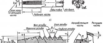
Design
Manufacturers are constantly improving their range of taps, optimizing their geometry for new materials and processing conditions. But the basic rod-shaped design remains unchanged. In the photo of the taps you can see a number of standard solutions, including the shank, working part, and grooves.
Each of them has its own purpose:
The grooves form cutting edges, remove chips, and facilitate the supply of coolant. They are oriented rectilinearly or along a helical line. Taps with left-handed helical recesses are used for through-threading. Blind holes are made with right-handed screws. The number of grooves varies in the range of 2-6 pcs.
The gauge section guides the tap, prevents the hole from breaking, and cleans the threads. To reduce friction, it is made with a reverse reduction in diameter to 0.1 mm.
Types by design
Taps vary greatly in their design:
- Fluteless have very short grooves and are used for working with tough materials: light metal alloys and some low-carbon high-alloy steels.
- Helical - grooves are arranged in an ascending spiral; they are used to cut threads in blind holes on high-performance machines.
- Stepped. The working part is divided into two zones, the first cuts and the second smoothes.
- Combined - there is a drill in front of the lead-in part, in one pass a hole is made and a thread is cut into it.
- Broaches. Used for cutting threads in through holes using a lathe.
- With an internal cavity for coolant supply.
- Bell type. They are used for cutting large diameters (up to half a meter) and consist of several cutting systems mounted in a common mandrel.
There are other tap designs for rare and special applications.
Threading tool
Die. On the outer surface the thread is cut into dies. They are made in the form of a nut. To obtain cutting elements and remove chips, holes are drilled in them. On each side the die has cutting elements that form a fence cone (angle 20⁰–30⁰). In the middle part there is a calibrating zone.
The die is fixed in the collar using screws. After each revolution of the die, you need to turn it back a third of the circle. This is necessary to clean the holes from chips and obtain a high-quality threaded surface.
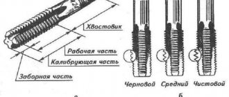
Tap. The tap is used for cutting internal threads. It has cutting edges obtained by making longitudinal or helical grooves. Grooves form the front surfaces on the teeth. The working area of the tap forms the sampling and calibrating sections. The fence section is also called the cutting section. It is conical in shape and penetration occurs gradually.
There are hand, machine and nut taps. Hand taps are made single and in sets: for roughing and finishing passes when cutting threads. The set also consists of 3 taps. Its number is indicated by the number of circular marks on the shank (1 - rough, 2 - semi-finish, 3 - finishing).
The roughing tap has the largest intake part. The shank of the taps is made in the form of a square in order to transmit the working force to the driver. Taps are subdivided for cutting threads in through and blind holes. Nut taps are made with a straight or curved shank.
Cutter. The thread is cut by the tip of the cutter, fixed in the support, as it moves relative to the rotating workpiece. In this case, the thread pitch formed by the cutter is equal to the distance between the tops of adjacent protrusions along the axis of the part.
Thread cutting with die heads
Thread-cutting screw heads are used for cutting external and internal threads on lathes, turret lathes and automatic lathes.
Using a shank, the threading head is installed in the tailstock quill or in the turret of the machine. Radial, tangential and round combs are used in screw cutting heads. At the end of thread cutting, the dies automatically diverge and do not come into contact with the thread during the return stroke.
When cutting external threads, heads with round combs are widely used, since they are simple in design, allow for many regrinds and have greater durability than radial and tangential combs. The design and operating principle of existing screw-cutting heads have minor differences.
Internal threads are most often cut with threading heads with prismatic combs, the cutting edges of which are located at the same diameter and have a lead-in cone. The number of combs included depends on the size of the head. The combs are offset in the set one relative to the other in accordance with the angle of the helix of the thread being cut.
When cutting long screws and worms, cutting heads are used to increase productivity, which are mounted on the machine support. These heads are equipped with ordinary and cup cutters and are used for cutting external and internal threads.
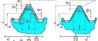
Profile and dimensions of a tapered inch thread with a profile angle of 60 degrees
This table shows what deviations there may be in slope and profile pitch.
Video: cutting tapered pipe threads.
As for additional fastenings, cotter pins are often used as connecting parts, since pipelines can be subject to vibration, both constant and periodic.
The thing is that this type of connection tends to unwind, so to avoid this, cotter pins are used for such connections. This is especially true for places where pipelines are laid under highways, where there is constant traffic movement, which creates vibrations.
A thread is a helical groove of a certain profile, cut on a cylindrical or conical surface. On lathes it is performed through two uniform movements - rotation of the workpiece and translational movement of the cutting tool along its axis. The threads used can be divided into a number of groups: 1) by location - external and internal; 2) by purpose - for fastening and running gear; 3) according to the shape of the original surface - cylindrical and conical; 4) in direction - to the right and left; 5) according to the profile shape - triangular, rectangular, trapezoidal, round; 6) by the number of passes - single and multi-pass. Fastening threads most often have a triangular profile. They are used to connect various parts. - Leading threads are used to convert rotational motion into linear motion. These include threads with a trapezoidal and, less commonly, rectangular profile. Tapered threads provide high tightness of the connection and are therefore used in places under high pressure of liquids and gases. For right-hand threads, the screw groove has a clockwise direction (when viewed from the end of the part), for left-handed threads it is the opposite. Single-start threads are threads that have one helical groove. Multi-start threads have several parallel helical grooves evenly spaced around the circumference. The number of thread starts can be determined by the number of starts of helical grooves at the end of the part.
Scope and tools.
Round dies are used for cutting external threads of a triangular profile on parts that do not have high requirements for thread alignment with other surfaces. The limits of the threads performed are limited by the mechanical properties of the metal being processed. So, for example, on lathes, round dies are used to cut threads on steel parts in increments of approximately 2 mm. For softer non-ferrous metals this limit may be increased. Threads with large pitches are pre-cut with a cutter and then calibrated with dies. Round dies (Fig. 118, a) in appearance resemble a nut, in which chip holes (from 3 to 8 depending on the size) are drilled to create cutting edges. The working part of the die for cylindrical threads consists of three sections: two outer sections - cutting and the middle one - calibrating. The cutting parts of the die are conical with a cone angle of 2f = 50-60°. The calibrating part is cylindrical. It gives the thread its final dimensions and provides direction to the die during the cutting process. The geometric shape of the die tooth is created by the rake angle, which is performed by sharpening within 15-20° (for centrally manufactured dies). When cutting hard metals, it is recommended to reduce it to 10-12°, and for soft metals - increase4 to 20-25°. The clearance angle a is performed by backing only on the cutting parts within 6-8°. For mounting in a die holder or thread-cutting chuck, conical recesses and an angular groove are provided on the outer surface of the die. The angular groove of the die allows, if necessary, to cut the die with a grinding wheel along the jumper (Fig. 118, b) and adjust its diameter within 0.1-0.3 mm. General purpose round dies are manufactured for the following threads: metric with large pitch Ml - M68; metric with small steps M1X0.2 - M135X6; inch 1/4-2″; pipe 1/8-1l/2″. The dies must ensure cutting threads of the 2nd accuracy class. Dies for tapered threads are wider and have only one cutting part on the larger diameter side. The peculiarity of the operation of the dies is that in the process of cutting a helical groove, not only the cutting part, but also the calibrating part is involved.
These dies are made for threads from 1/16″ to 2″. Dies are made of alloy steel 9ХС or high-speed steels Р9 and Р18. The dies are marked with the thread designation, accuracy class (3rd only), steel grade (9ХС is not indicated), and the letter L for left-hand threads.
Quality control
To ensure that the workpiece has been processed correctly, it is necessary to use thread templates. With their help, the thread pitch is checked.
But for a comprehensive assessment, a thread gauge is used. For convenience, it is installed in a rack and adjusted according to a standard or template, then the movement of the part itself is checked.
You can also use the simplest and most commonly used method. Take a nut or bolt and scroll it over the completed part.
If scuffing is noticeable on the thread as you move, or more effort needs to be applied, then you have made an error in your work. Now you already know how to use a lathe to make various nuts, bolts or threaded connections.
It is important to remember that such parts require great care and tenderness with each pass, and even quality control. It’s better to spend more time on work than to ruin several pieces later