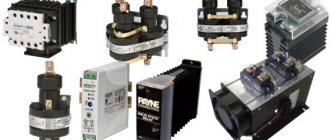
A thyristor is a semiconductor device with a pnpn structure that plays the role of a switch in circuits with high currents, while it is controlled by a low-current signal. It is used to switch on power electric drives and generator excitation systems. Switched currents reach up to 10 kA.
The peculiarity of thyristors is that when a control signal is applied, they open and remain in this state, even if the signal is subsequently removed. The only requirement is that the current flowing through them must exceed a certain value, which is called the holding current.
Some thyristors only allow current to flow in one direction. These are dinistors that are triggered when a significant voltage is exceeded. There are also SCRs controlled by supplying current to the third terminal of the device.
Thyristors that pass current in both directions are called triacs or triacs. In addition, there are photothyristors controlled by light.
Main characteristics
To check the SCR, you need to know and understand what is hidden behind the main parameters and why they need to be measured.
The control unlocking voltage Uy is a constant potential on the control electrode, causing the thyristor to open.
Urev max is the maximum reverse voltage at which the thyristor is still in working condition.
Ioc cp is the average value of the current flowing through the thyristor in the forward direction while maintaining its operability.
Limitation of voltage slew rate du/dt
With a forward voltage drop, a forward voltage is applied to the external junctions J1 and J3 (block diagram here), and a reverse voltage is applied to the internal junction J3. J3 has an equivalent capacitance, which will result in current flow when voltage is applied:
Where: CJ – junction capacitance.
If the rate of change of voltage across the thyristor is too high, the transition current may reach a value that is sufficient to turn on without applying a control pulse. Such a switching effect without a control pulse under the influence of du/dt can lead to very serious malfunctions in the operation of not only the converter, but also the devices controlled by the converter.
The permissible du/dt change rate is usually in the range of 20-500 V/µs. To protect the thyristor from unintentional switching on at high du/dt, parallel RC circuits are used.
Determination of control voltage
Now you can start testing the SCR. To do this, let's take KU202N with an operating current of 10 A and a voltage of 400 V.
Most radio amateurs have a multimeter and the question inevitably arises of how to check a thyristor with a multimeter, whether this is possible and what additional things may be needed. The sequence of actions is as follows:
First, switch the multimeter to the resistance measurement position with a range of 2 kOhm. In this mode, the voltage of the tester's internal power supply will be present on the test leads;- We connect the probes to the anode and cathode of the SCR. The multimeter should show a resistance close to infinity;
- We connect the anode and the control electrode with a jumper. The resistance should drop, the SCR has opened;
- We remove the jumper, the device again shows infinity. This is due to the holding current being too low.
Since the thyristor is controlled by both negative and positive signals, it can be opened by connecting the control electrode to the cathode with a jumper.
The multimeter should be in ohmmeter mode and the probes connected to the anode and cathode. This way you can determine what voltage the thyristor is controlled by.
Design and principle of operation
The thyristor device looks like this:
- 4 semiconductor elements are connected in series with each other, they differ in the type of conductivity.
- The design has an anode - a contact to the outer layer of the semiconductor and a cathode, the same contact, but to the outer n-layer.
- In total there are no more than 2 control electrodes , which are connected to the internal layers of the semiconductor.
- If the device completely lacks control electrodes , then such a device is a special type - a dinistor. If there is 1 electrode, the device belongs to the class of thyristors. Control can be carried out through the anode or cathode; this nuance depends on which layer the control electrode was connected to, but today the second option is the most common.
- These devices can be divided into types , depending on whether they pass electric current from the anode to the cathode or in both directions at once. The second version of the device is called symmetrical thyristors, usually consisting of 5 semiconductor layers; in essence, they are triacs.
- If there is a control electrode in the design , thyristors can be divided into lockable and non-lockable varieties. The difference between the second type is that such a device cannot be transferred to a closed state in any way.
- The device is turned on due to the receipt of electric current pulses by the circuit. The supply occurs at a polarity that is positive relative to the cathode.
- The length of the transition process is influenced by a number of different factors: type of load; semiconductor layer temperature; voltage indicator; load current parameters; the speed at which the control current increases and its amplitude.
- Despite the significant steepness of the control signal , the rate of voltage rise should not reach unacceptable levels, as this may cause a sudden shutdown of the device.
- Forced shutdown of the device can be done in different ways; the most common option is to connect a switching capacitor with reverse polarity to the circuit. Such a connection can occur due to the presence of a second (auxiliary) thyristor, which will trigger a discharge to the main device. In this case, the discharge current passing through the switching capacitor will collide with the direct current of the main device, which will reduce its value to zero and cause a shutdown.
principle of operation
The principle of operation of a thyristor connected to an alternating current circuit is slightly different:
- In this position, the device can turn on or off circuits with different types of load, as well as change the values of the electric current through the load. This occurs due to the ability of the thyristor device to change the moment at which the control signal is supplied.
- When connecting a thyristor to such circuits , only back-to-back connection is used, since it can only conduct current in one direction.
- The electric current indicators change due to changes being made at the moment when the opening signals are transmitted to the thyristors. This parameter is regulated using a special control system of the phase or pulse width type.
- When using phase control , the electric current curve will have a non-sinusoidal shape, this will also cause a distortion of the shape and voltage in the electrical network from which external consumers are powered. If they are highly sensitive to high-frequency interference, this may cause malfunctions during operation.
Functionality check
The second testing option is as follows. A lamp at the same voltage is connected to the DC power supply through a thyristor.
A multimeter is connected to the anode and cathode in DC voltage measurement mode. The measurement range must be greater than the source voltage.
Then, control voltage is supplied to the control electrode using a battery of any rating and a pair of wires. The thyristor should open and the light should light up.
The tester first shows the voltage of the power source, after exposure to a small value, which corresponds to the potential drop across the thyristor in the open state.
After this, you can remove the control action, the lamp will continue to burn, since the current flowing through the device is greater than the holding current.
Device diagnostics
Checking the starter solenoid relay with a multimeter
When checking a radio element for serviceability, a multimeter is most often used. The ease of use of this measuring device is explained by its versatility. It can be used to test an element for breakdown or measure threshold voltage levels
It does not matter whether the meter is analog or digital
To obtain correct measurement results, you will need to prepare the multimeter for use. The whole essence of the preparatory operation comes down to checking the battery of the tester
When working with a digital device, you must pay attention to the flashing battery icon. If it is, then the battery needs to be replaced.
For an analog device, the arrow is set to the zero position before operation. If this cannot be done, then the battery must be replaced.
For a reliable result, when measuring with a multimeter, it is also advisable to monitor the ambient temperature. This is due to the fact that as the temperature increases, the conductivity of semiconductors increases. The optimal temperature for measurement is considered to be around 22 °C.
Continuity without soldering
Due to the specifics of the device, checking the triac with a multimeter without desoldering is not so easy. For a complete check, an electrical circuit is used that allows you to carry out a number of necessary measurements. The only thing that can be done with a multimeter is to check it for obvious breakdown.
To do this, the tester switches to the diode vertebrae mode, after which the measuring probes touch the dinistor terminals. For any polarity, the tester should show a break, which will indicate the absence of a breakdown in the element. But this will not guarantee the serviceability of the device. If during measurement the multimeter shows a short circuit, then such a thyristor can no longer be checked, since it is faulty.
At the same time, you should know that ringing a radio element in the circuit will be incorrect, since other radio elements that affect the measurements can be connected in parallel with its output. When performing a simple test, you need to disconnect at least one of the dinistor inputs from the printed circuit board. In order to check the dinistor without desoldering, you can use the capabilities of the circuit in which it is installed.
In this case, the multimeter switches to voltage measurement mode to check. Depending on the expected breakdown voltage, the measurement range is selected. The measuring probes are connected in parallel to the terminals of the element, after which the signal level is measured. If a voltage surge occurs when the input signal changes, this will indicate the breakdown voltage of the dinistor, that is, its performance.
https://youtube.com/watch?v=pndQx1nu0PA
Test circuit
To gain confidence in the functionality of the element, radio amateurs use test circuits. They come in varying degrees of complexity, which ultimately affects the accuracy of the result obtained. The simplest scheme consists of three elements:
- regulated power supply;
- resistor;
- indicator.
As the latter, you can use an LED. Having assembled such a diagram, we begin to check. A tester is connected parallel to the element in voltage measurement mode.
For example, to check the KU202N thyristor with a multimeter, first set the output voltage level to about twenty volts. In this case, the LED in the circuit should not light up. The level then slowly rises until the LED lights up. The glow of the indicator indicates that the dinistor has opened and electric current has begun to flow through it. To close it, the voltage level is reduced.
The value of the potential difference at which the operating mode changes is the maximum opening voltage. In this case, the tester should show a value of about 50 volts, while the input signal level will be about 60 volts. Any type of resistor can be used. Its purpose is to limit the amount of current passing through the LED.
Knowing how to test the KU 202 thyristor, you can test any other type of thyristor, dinistor or triac. It should be noted that professionals use an oscilloscope instead of a multimeter. A test attachment is used together with it. The elements to be measured are connected to sockets X5 and X6. When using a thyristor, its control element is connected to socket X7. For elements with a control output, the voltage is changed using variable resistor R4. If the radio element is intact, then the oscillogram should be the same as in the figure.
Checking the dinistor
To determine the performance of the dinistor, a power source with a voltage higher than the turn-on voltage of the dinistor may be required.
To limit the current you will need a 100-1000 Ohm resistor. Now you can connect the plus of the source to the anode, and the cathode to one of the terminals of the limiting resistor.
The second end of the resistance is connected to the minus of the power source . Before this, you need to connect a multimeter in DC voltage measurement mode to the anode and cathode.
The tester values should be within millivolts. The dinistor opened.
Thyristor overvoltage protection
The process of semiconductor operation does not always take place under normal conditions. Sometimes, during lightning strikes, unsatisfactory switching conditions, or transient processes, overvoltage may occur on a semiconductor switch. To protect against overvoltages, nonlinear elements are used, the resistance of which depends on the voltage (for example, a zener diode). They are connected in parallel to the element, and at high voltages they bypass the power circuit.
Unusual way
There is another option for checking the thyristor with a multimeter, without ringing. But in this case, the device must be low-power, with a low holding current.
The transistor test connector is used for testing. It is usually located below the switch and is a round connector approximately 1 cm in diameter.
It should have the following designations: B - means the base of the transistor, C - collector, E - emitter.
If the thyristor opens with a positive voltage, then the control terminal must be connected to the base, the anode and cathode to the collector and emitter, respectively.
Since the tester measures the gain when testing a transistor, even in this case it will give some values that will be incorrect. But this is not important, the main thing is to make sure that the thyristor is working properly.
Adviсe
In conclusion, we can give the following several recommendations that may be useful when checking thyristor devices:
- In some situations, it is advisable to carry out not only a serviceability check, but also a selection of tested devices according to their parameters. Special equipment is used for this, but the process itself is complicated by the fact that the power source must have an output voltage of at least 1000V.
- Often , testing is performed using multimeters or testers, since such testing is the easiest to organize, but you need to know that not all models of these devices are capable of opening a thyristor.
- The resistance of a broken thyristor most often has values close to zero. For this reason, a short-term connection of the anode of a working device with the control electrode shows resistance parameters that are characteristic of a short circuit, and a similar procedure with a faulty thyristor does not cause a similar reaction.
Thyristors, as a separate type of semiconductor, belong to the category of diodes. But unlike them, the thyristor has a third terminal designed to perform the tasks of the control electrode.
In actual sense, it is a diode with three terminals. Such semiconductor devices are widely used in household appliances and in power regulators of various light sources.
Read also: Blade for a walk-behind tractor made from a gas cylinder
Considering the scale of use of the thyristor, many home craftsmen are faced with the problem of the device failing, but they do not know how and with what to test it. So, first, you need to understand what it is and what its principle of operation is.
Check in the circuit
Sometimes it is necessary to check a thyristor without removing it from the circuit. To do this, the control electrode must be disconnected. After this, a multimeter is connected to the anode and cathode in DC voltage measurement mode.
The second tester is connected to the anode and control electrode of the thyristor. The second device must be in ohmmeter mode.
If the test leads are connected correctly, the readings of the first tester will be within a few tens of millivolts.
If not, then the probes need to be swapped and everything repeated. Before measurements, you need to make sure that the board and the entire device are de-energized.
Tools and materials for testing
To test the device, the following tools and materials may be required, depending on the selected testing method:
- power supply or battery, which will act as a constant voltage source;
- incandescent lamp;
- wires;
- ohmmeter;
- multimeter;
- tester;
- soldering machine;
- thyristor;
- soldering machine;
Also, to test the correct operation of the thyristor, you may need to have a probe that you can make yourself.
It will require the following materials and elements:
- pay;
- resistors, quantity 8 pieces;
- capacitors, quantity 10 pieces;
- diodes, quantity 3 pieces;
- positive and negative stabilizer;
- incandescent lamp;
- transformer;
- fuse;
- toggle switch, quantity 2 pieces;
There are a number of possible schemes for making a probe; you can choose any one, but you must follow the following recommendations:
- All elements are connected using special wires with clamps.
- It is necessary to consistently monitor the voltage between different contacts. To carry out testing, it is possible to connect switches to different contact groups.
- After assembling the circuit, it is necessary to connect the thyristor; if it is in good condition, the incandescent lamp will not turn on.
- If the light bulb does not light up even after pressing the start button, then it is necessary to increase the value of the control electric current using the installed switch. If the corresponding circuit is broken, the light bulb goes out.
Protection against emergency currents
Semiconductors have a relatively small heat capacity, so they do not tolerate overload, operation with pulsed currents, as well as short-term surges of current. To ensure protection against such modes, good old proven methods are used, namely, circuit breakers and fuses. Circuit breakers provide protection against overloads, and fuses provide protection against short circuits. The response time of the protective equipment must correspond to the characteristics of the protected elements. Also, the most important factor should be to disconnect the device from the network in the event of emergency situations before it fails. It is based on this condition that protective equipment is selected.
Circuit protection
The protections discussed above may not always provide the required level of protection. To organize the protection of thyristor converters, a large number of circuit solutions can be used. The most common of them is blocking control pulses. They can also use an additional parallel thyristor, which will bypass the main one until the main protection (circuit breaker) trips.
A circuit with a capacitive damping device is possible; it is applicable for inverters with emergency mode when the elements of one arm are turned on. Applicable for inverters with current reversal, it consists of a capacitor with a small capacity, connected directly to the filter reactor. When two elements are turned on simultaneously, the current is transferred to a quenching capacitor, and the negative half-wave, which is formed in the oscillatory LC circuit, inhibits the thyristors. Well, and, accordingly, the parameters of the reactor and capacitor are selected in such a way that the currents generated in a given circuit do not exceed the permissible currents of the elements. The fuse should not blow with each current pulse. Moreover, this circuit can also be used as a switching circuit.
