Many technical devices, as well as most household items, have threaded connections, which humanity began to use since ancient times. The main tools with which the elements of such connections are made include a tap. Its use allows you to quickly and without much difficulty cut precise and high-quality threads on the inner surface of the hole.
Thread taps
Design features
The first tools for cutting internal threads were distinguished by a primitive design and consisted of a tetrahedral rod, at the working end of which, sharpened to a shallow cone, cutting teeth were sawn out. When using such a tap, the thread was cut by screwing it into the inside of the nut or into a previously prepared hole in the workpiece. Naturally, such a tool had many disadvantages, the most significant of which include the absence of a rear surface on the cutting part, as well as a negative rake angle. Over time, the design of taps has become more sophisticated, and today they allow you to create accurate and high-quality internal threads.
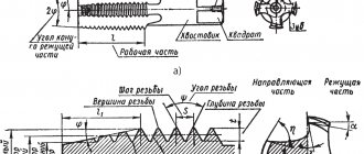
Any tap for cutting threads on the internal surfaces of workpieces, regardless of its geometric parameters and purpose, contains the following elements:
- side grooves (there can be from 2 to 6);
- conical intake part;
- calibrating part, which has a cylindrical shape.
Tap design
The grooves located on the side surface of the tool along its entire length simultaneously perform two functions: ensuring the removal of chips from the processing zone and facilitating the supply of coolant lubricant (coolant) to such a zone. The shape that the groove of the tap has in cross section is determined by its two surfaces, one of which is the front edge of the cutting tooth of the tool, and the second is its back. Depending on the type of profile, chip flutes are of the following types:
- single-radius (with grooves of this shape, mainly calibration type taps are produced);
- with straight front and back surfaces (tools with grooves of this shape are used for cutting threads inside nuts);
- with a straight front and radius back surfaces (most taps are manufactured with this type of flute).
Tap flute profiles
The grooves can be located in different ways: there are straight grooves, as well as spiral right or left. Universal taps for general use are manufactured with straight-type grooves. Spiral left-handed flutes produce taps used for cutting threads for passages. The chips created by such a tool move ahead of it along the hole being processed, thereby eliminating the risk of damage to the already cut thread. When using taps with the right direction of twisting of the grooves, the chips are removed from the processing zone to the tool shank. For this reason, right-handed taps are ideal for cutting threads in blind holes.
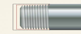
The intake part of the tap, as mentioned above, has a conical shape, which facilitates the process of inserting the tool into the hole being machined. The specific value of the angle of inclination of the intake part, which can be in the range of 3–20°, is selected depending on what type of processing the tool will be used for - roughing, intermediate or finishing.
Tap designs according to GOST
The cylindrical calibration part is made with a reverse reduction of up to 0.1 mm, which is necessary in order to reduce the friction forces arising during the thread cutting process. The friction force between the working part of the tap and the machined surface can also be reduced by backing the back surface of the cutting teeth, carried out from their top to 1/3 of their width. This creates a reduction in the back surface of the cutting teeth, the value of which for tools with a diameter of 12–30 mm is about 0.1 mm.
Geometry of the cutting and calibrating part of the tap
Types by purpose
Modern industry produces various types of taps, which differ from each other in design and functionality. Thus, according to their purpose, taps can belong to one of the following types.
Locksmith
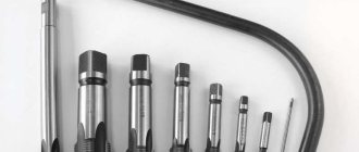
These tools are most often hand-held and are used in conjunction with a special crank, with the help of which rotation is imparted to the tap. As a rule, they are produced and used in sets consisting of two or three tools, each of which removes only part of the allowance from the surface being processed. The dimensions of the taps included in this kit (in particular, their working diameters) vary. The first of the tools, on the shank of which is marked in the form of one line, is used for roughing, the second (with two lines on the shank) is used for intermediate processing, and the third (with three lines, respectively) is used for finishing the thread being cut.
Complete hand taps
Machine or machine-hand
These are tools with which threads can be cut both manually and on various types of machines (lathes, drills, aggregates, etc.). Such taps differ from metalwork taps only in that they have a slightly shorter fence part and higher resistance to mechanical loads.
Machine-manual triple taps
Nuts
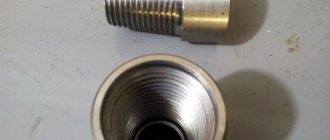
With the help of such tools, as their name suggests, they cut threads in nuts. Nuts, which have already been threaded with such a tap, are not twisted from the tool, but are moved to its elongated tail part. The shanks of nut taps, with which threads are cut on drilling machines, have a rectilinear shape. Nuts with already cut threads, moved to such a shank, are simply shaken off it after removing the tool from the machine chuck. To cut nuts, automatic threading machines use taps whose shanks have a curved shape. When carving in this way, the nuts, under the pressure of each other, are pushed along the curved shank of the tool, reach its end part and fall into the prepared container.
Tapping threads with a nut tap
Requirements for the design and dimensions of both manual and machine taps for cutting metric threads are specified by GOST 3266-81, which is called: “Machine and hand taps. Design and dimensions."
You can familiarize yourself with the GOST requirements for manual and machine taps by downloading the document in pdf format from the link below.
GOST 3266-81 Machine and hand taps. Design and dimensions
Accuracy classes
In accordance with GOST, there are three accuracy classes for inch threads, designated by numbers 1, 2, 3. The degree of accuracy increases with increasing class numbers. Thus, class 1 includes threads that have minimum accuracy requirements. Class 3 threads are the most accurate and the most stringent requirements apply to their dimensions.
When designating the accuracy class, the letters A (for external) and B (for internal) are also used to indicate the type of thread. Accordingly, the full designations for external threads are presented as 1A, 2A and 3A, and for internal threads - 1B, 2B and 3B.
Types by design
According to their design, taps are also divided into various types. So, depending on this parameter, the tools are distinguished:
- with chip flutes of shortened length, which are also called fluteless (the design of such taps is specially designed for cutting threads in parts made of tough low-carbon steels, aluminum alloys, and high-strength alloy steels);
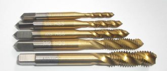
- with grooves located along a helical line (such tools are installed on machining centers and used for cutting blind threads);
- with cutting teeth placed in a checkerboard pattern (due to the fact that the cutting teeth on the calibration part of such a tool are cut one after another, it is possible to reduce the friction force during processing);
- stepped type with a working part divided into two sections, each of which performs its own function (for example, there are stepped taps, the first section of which works according to a generator circuit, and the second - according to a profile; for stepped tools of other types, the first section performs a cutting function, and the second – smoothing);
- combined (these are actually two tools in one: their cutting part, made in a single design, starts with a drill and ends with a tap);
- broach taps used for cutting threads in a through hole of any diameter (with their help, threads are cut on lathes, in the chuck of which the workpiece is fixed, and in the tool holder - the shank of the tool used; the movement of the tap during the thread cutting process is ensured by the automatic feed of the machine support, and the rotation of the workpiece is by rotating the spindle);
- with an internal cavity, due to which the tool is cooled during processing (the use of such taps installed on specialized or multi-operational equipment can significantly increase thread cutting productivity);
- bell (such taps are used for cutting internal threads of large diameter (50–400 mm) and have a prefabricated structure consisting of individual cutting elements).
Designs of the main types of taps
Structurally, all the taps listed above are so different from each other that you can even tell them apart from a photo.
Types of threads to be cut
Using taps of different categories, as well as different types of dies, it is possible to form threads of various types on the internal surfaces of parts. Depending on the type of thread being cut, taps are divided into the following categories.
Metric
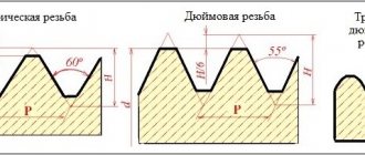
These are taps that are used to cut metric threads. The cut thread element in such cases has the shape of an isosceles triangle, and all its parameters are measured in millimeters. The markings of such taps contain the letter “M”. To select metric taps and the diameter of the preparation hole, a special reference table is used.
Inch
The working part of such taps has a conical shape. The diameter of inch tools is measured in inches, and the pitch is measured in the number of threads per inch (25.4 mm). The slope of the average surface of taps of this type is 1°47'24".
Pipe
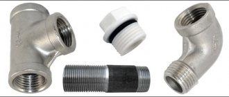
This includes cylindrical and conical taps used for cutting threads in pipe fittings.
Table 1. Tap parameters and thread hole size
Taps can be used to make holes with both right-hand and left-hand threads. Taps for left-hand threads, when compared in reality or from photos with right-handed tools, differ from the latter only in the direction of the rise of the helical line of their cutting part.
How to correctly determine the hole diameter?
Before cutting a thread, a hole is made, the diameter of which is determined according to standardized tables. If you prepare a hole whose cross-section is smaller than the recommended size, the tool will fail; if it is larger, the result will be of poor quality.
Correspondence table for metric threads and hole diameters for them
| Thread designation | Diameter, mm | Thread designation | Diameter, mm | Thread designation | Diameter, mm |
| M 2 | 1,6 | M 8 | 6,7 | M 22 | 19,4 |
| M 2.2 | 1,75 | M 9 | 7,7 | M 24 | 20,9 |
| M 2.5 | 2,05 | M 10 | 8,5 | M 27 | 23,9 |
| M 3 | 2,5 | M 11 | 9,5 | M 30 | 26,4 |
| M 3.5 | 2,9 | M 12 | 10,2 | M 33 | 29,4 |
| M 4 | 3,3 | M 14 | 12,0 | 31,9 | |
| M 5 | 4,2 | M 16 | 14,0 | M 39 | |
| M 6 | 5,0 | M 18 | 15,4 | M 42 | 37,4 |
| M 7 | 6,0 | M 20 | 17,4 | M 45 | 40,4 |
Correspondence table for inch threads and hole diameters for them
| Thread size, inches | Diameter, mm | Thread size, inches | Diameter, mm |
| 1/8 | 8,8 | 7/8 | 28,1 |
| 1/4 | 11,7 | 1 | 30,5 |
| 3/8 | 15,2 | 1 1/8 | 35,2 |
| 1/2 | 18,9 | 1 1/4 | 39,2 |
| 5/8 | 20,7 | 1 3/8 | 41,6 |
| 3/4 | 24,3 | 45,2 |
