Unit characteristics
The device has the following technical characteristics, which are contained in the device passport:
- machine weight - 100 kg;
- length, width and height of the device, respectively - 700*300*800 mm;
- number of grooves - 1;
- desktop surface parameters - 251*280 mm;
- the maximum distance from the table to the end of the spindle is 40 cm; • spindle speed is 699-4000 rpm;
- the distance from the axis of the vertical spindle to the guides is 160 mm;
- spindle sleeve stroke indicator - 10 cm;
- spindle cone type - Morse 2B.
The machine's passport indicates that its spindle has no speed. The unit is equipped with an electric motor with a power of 0.5 kW.
2A112 tabletop drilling machine with variator. Passport, diagrams, characteristics, description
Manufacturers of the tabletop drilling machine model 2A112 are secondary technical educational institutions with their own production base.
The machine is designed for drilling holes and cutting threads in small parts made of cast iron, steel, non-ferrous alloys and non-metallic materials in industrial enterprises, repair shops and household workshops.
The simplicity of the design ensures ease of control, reliability and durability of the machines.
The variator is the main feature of the 2a112 drilling machine. A variator is a mechanism for steplessly regulating the spindle speed from 700 to 4000 rpm at a constant speed of rotation of the motor shaft. The original design of the belt drive tension allows you not to monitor the belt tension while changing the spindle speed.
The drilling depth is measured using the dial on the shaft of the spindle manual feed handle.
2A112 machines allow you to perform the following operations:
- drilling
- countersinking
- deployment
- reaming
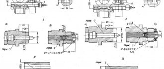
General view of the drilling machine 2A112
Kinematic diagram of the drilling machine 2A112
Specification of components of the drilling machine 2A112
- Driven pulley (variator)
- Spindle quill (spindle sleeve)
- Rack and pinion gear for moving the spindle quill
- Rack and pinion gear for moving the spindle head (traverse)
- Drive pulley
- Pressure spring
- Rack column 308 mm long
- Bracket for fastening the column to the slab
- Headstock
- Headstock clamping device on column
- Electric drive
- Stove (work table)
- Engine plate
- Spindle
- Drive belt cover
- Spindle manual feed handle
- Handle for fixing the spindle head on the column
- Handle for moving the spindle head along the column
- Motor control buttons
- Nut for adjusting spindle speed
Location of controls for drilling machine 2A112
Specification of machine controls 2A112
Design of drilling machine 2A112
The drive of the main movement is carried out from the DPD22-4 or A09 electric motor through a V-belt drive (textrope V-shaped belt). The movement is transmitted from the drive pulley to the driven pulley and then to the spindle and tool.
The spindle rotation speed is infinitely adjustable using a nut located under the spindle pulley. When unscrewing the nut through the thrust bearing, the pressure on the lower part of the variator pulley increases, the diameter of the pulley increases, and the spindle rotation speed decreases. At the same time, the tension of the drive belt increases, which leads to the fact that the halves of the drive pulley move apart and the diameter of the pulley decreases, but the belt tension remains constant.
The machine operates with manual feed. The feed is carried out from the handle through the rack and pinion gear 3, the quill 2 and the angular contact bearing to it. The height of the spindle head is set by the rack and pinion handle 4 and clamped by the clamp handle on the column.
ATTENTION!
Change speed only on the go.
The principle of operation of the variator of the drilling machine 2A112
The figure on the left shows the drive pulley on top of which the pressure spring is cut through in an uncompressed and compressed state. The force of the pressure spring regulates the belt tension.
On the right is a driven pulley at the bottom of which there is a thrust bearing in section. The thrust bearing is located between the lower pulley plate and the round nut that regulates the diameter of the driven pulley.
Spindle with variator assembly
Spindle with variator assembly
Parts of the variator and spindle of the machine
Parts of the variator and spindle of the machine
Details of the drive pulley of the drilling machine 2A112
The upper end of the spring rests against the bottom of the cup screwed onto the bushing, the lower end rests against the pin of the upper plate of the composite pulley.
The lower plate of the pulley is fixed motionless on the bushing, the upper plate moves along the bushing, depending on the tension of the belt and the spring setting, thereby changing the diameter of the pulley.
Variator parts of drilling machine 2A112
Quill and spindle of drilling machine 2A112
Mechanism for raising and lowering the quill (spindle sleeve) assembly
The mechanism for raising and lowering the quill consists of:
- Spindle manual feed handle
- Rack and pinion
- Bushing with return spring
- Limbo
Details of the mechanism for raising and lowering the quill (spindle sleeve)
Mechanism for raising and lowering the spindle head
Details of the mechanism for raising and lowering the spindle head
Clamping mechanism of the spindle head on the column
Electrical equipment and electrical circuit of the drilling machine 2A112
Parameter name 2M112 2A112
| Basic machine parameters | ||
| Largest drilling diameter, mm | 12 | 12 |
| The smallest and largest distance from the end of the spindle to the table | 0..400 | 0..400 |
| Distance from the axis of the vertical spindle to the rack guides (overhang), mm | 190 | 160 |
| Desktop | ||
| Width of the working surface of the table, mm | 250 | 250 x 280 |
| Number of T-slots | 3 | 1 |
| Spindle | ||
| Maximum movement of the spindle head (traverse) along the column, mm | ||
| Spindle sleeve stroke, mm | 100 | 100 |
| Spindle speed, rpm | 450, 800, 1400, 2500, 4500 | 700..4000 |
| Number of spindle speeds | 5 | b/s |
| Spindle taper | Morse B18 | Morse 2B |
| Drive unit | ||
| Main motion drive electric motor, kW | 0,55 | 0,5 |
| Dimensions and weight of the machine | ||
| Machine dimensions (length width height), mm | 795 x 370 x 950 | 700 x 300 x 800 |
| Machine weight, kg | 120 | 100 |
Related Links
Catalog reference tabletop drilling machines
Certificates for tabletop machines
stanki-katalog.ru
Purpose of the machine and its features
Devices 2a112 are capable of performing 4 types of operations:
- deployment;
- drilling;
- reaming;
- countersinking.
The main design feature of the machine is the presence of a special mechanism in it - a variator. The variator is a device for steplessly adjusting the spindle speed, taking into account the fact that the rotation speed of the motor shaft remains unchanged.
When the spindle speed changes, the operator does not need to tighten the belt. This is due to the presence in the design of the device of a belt tension system. The unit belongs to the class of light machines, as indicated by its passport.
Technical characteristics of the machine 2A112
| Parameter name | 2M112 | 2A112 |
| Basic machine parameters | ||
| Largest drilling diameter, mm | 12 | 12 |
| The smallest and largest distance from the end of the spindle to the table | 0..400 | 0..400 |
| Distance from the axis of the vertical spindle to the rack guides (overhang), mm | 190 | 160 |
| Desktop | ||
| Width of the working surface of the table, mm | 250 | 250 x 280 |
| Number of T-slots | 3 | 1 |
| Spindle | ||
| Maximum movement of the spindle head (traverse) along the column, mm | ||
| Spindle sleeve stroke, mm | 100 | 100 |
| Spindle speed, rpm | 450, 800, 1400, 2500, 4500 | 400..4000 |
| Number of spindle speeds | 5 | b/s |
| Spindle taper | Morse B18 | Morse 2A |
| Drive unit | ||
| Main motion drive electric motor, kW | 0,55 | 0,5 |
| Dimensions and weight of the machine | ||
| Machine dimensions (length width height), mm | 795 x 370 x 950 | 700 x 300 x 800 |
| Machine weight, kg | 120 | 100 |
Bibliography:
Glukhov N.M. Work on coordinate boring machines, 1953 Grigoriev S.P., Grigoriev V.S. Practice of coordinate boring and milling work, 1980 Kashepava M.Ya. Modern jig boring machines, 1961 Kudryashov A.A. Tool production machines, 1968 Bernstein-Kogan V.S. Electrical equipment of jig boring and thread grinding machines, 1969 Ipatov S.S. Jig boring machines in precision instrumentation, 1954
Related Links
Catalog reference tabletop drilling machines
Certificates for tabletop machines
Home About the company News Articles Price list Contacts Reference information Download passport Interesting video KPO woodworking machines Manufacturers
The main purpose of the 2a112 drilling machine is to cut threads and drill holes in cast iron, steel products and parts made of non-ferrous alloys. The device is used for drilling non-metallic products. The unit is used in repair shops, industrial enterprises and small workshops.
Device design
The basic element of a tabletop drilling machine is the bed. It is a one-piece cast structure made of cast iron.
There is a T-shaped groove on the desktop of the device. It is used for fastening vices and other devices intended for the machine.
The drilling machine is equipped with a metal column with a rack. The rack has cut teeth located on the outside of the column itself.
The unit has a traverse, which is a horizontally located solid cast metal structure, equipped with a cone at the end. The height from the edge of the traverse cone to the surface of the work table is 400 mm.
The height of the traverse can be adjusted using the rack and pinion gear located on it. Inside the mechanism there is a clamp, due to which the traverse is fixed in a certain position. The pressure is adjusted using a handle located on the back of the device.
The variator of the unit is designed so that the halves of the pulley are moved apart or moved by rotating the nut. In this case, the working diameter of the pulley changes.
The tension of the drive belt is constant. It is provided by a mechanism located on the shaft of the electric motor.
The quill is ejected using a flywheel mounted on a traverse.
The spindle of the unit has a Morse taper 2B, as indicated by the device passport. A quick-release chuck is mounted on the spindle and requires periodic replacement.
The electrical equipment of the machine is represented by a three-phase AC motor. The engine operates at mains voltages of 220 V and 380 V.
What is the 2M112 machine and where is it used?
The 2M112 machine, which belongs to the vertical drilling category, began production in 1980. Over a fairly long period of its existence on the market, this device has gained enormous popularity when used in home workshops and workshops of small manufacturing enterprises. 2M112 machines, designed for desktop use, are also included in the equipment of training workshops of schools and vocational educational institutions, where young specialists are trained on them.
The technical capabilities of the drilling machine in question allow you to perform a number of technological operations:
- drilling holes;
- reaming;
- deployment;
- countersinking;
- internal thread cutting.
You can install a rotary vice on the machine's work table
The material used to manufacture the parts processed on such a drilling machine can be metal, plastic or wood.
Despite the simplicity of the design, the 2M112 desktop drilling machine provides the ability to change the rotation speed of the working chuck in 5 steps. To implement this function, the position of the belt on the belt drive pulleys changes on the unit, which is done very quickly thanks to the special design of this unit. The drilling depth when working on the 2M112 drilling machine is also adjusted quite simply - a flat scale (or stops) is used for this.
Belt drive under raised machine guard
The simple design provides the main advantages of the 2M112 vertical drilling machine - exceptional reliability and ease of use. This machine is distinguished by such characteristics as compact dimensions (795x390x950 mm) and low weight (120 kg), which makes it easy to move such equipment to any place. Due to its compactness, the model 2M112 vertical drilling machine can be installed both on the surface of a mechanic’s table and on a special drilling column or stand.
The principle of operation of the machine mechanisms
The machine operates on an electric motor through a V-belt drive. The main movement is driven from it. The movement begins to be transferred from the driving spindle to the driven one, after which it is transferred to the spindle and the working tool.
The nut regulates the spindle rotation speed. It is located under the spindle pulley.
The operating principle consists of the following stages:
- the nut is unscrewed through the thrust bearing;
- there is an increase in pressure on the lower part of the variator;
- the pulley diameter increases;
- at the same time, the spindle rotation speed decreases;
- the pulley halves move apart due to belt tension;
- The diameter of the pulley decreases with constant belt tension.
The device operates with manual feed. It comes from the handle through several mechanisms at once:
- quill;
- rack and pinion;
- thrust radial bearing.
The height of the spindle head is adjusted using the handle. It is equipped with a rack and pinion gear. In the process of adjusting the height of the headstock, it is clamped by a handle located on the column of the machine.
Location of controls for drilling machine 2A112
Location of controls for drilling machine 2a112
Specification of machine controls 2A112
- Spindle manual feed handle
- Handle for fixing the spindle head on the column
- Handle for moving the spindle head along the column
- Motor control buttons
- Nut for adjusting spindle speed
Operating rules
The drill model 2a112 requires compliance with a number of rules before starting work and when performing operations on it.
A preliminary check of the strength of the drill fastening is required. During the work process, a smooth approach of the drill to the workpiece is necessary. The transmission is engaged until the drill comes into contact with the workpiece. The feed rate decreases as the drill exits the hole formed in the part.
Removing short chips that wrap around the drill is done with a hook. Long chips are removed only after the machine stops. Maintenance of the device includes:
- changing the oil in the gearbox after 90 hours of operation;
- removal of coal dust from the electric motor after 90 hours of operation;
- complete cleaning of the unit after each start-up;
- after disassembling and assembling the device, it must be checked for electrical safety;
- Constant inspection of brushes and their replacement if the height is less than 8 mm.
