Selecting a welding mode: current strength, arc length, polarity
To obtain a high-quality and reliable welding seam, you need to understand which electrodes are best to use and which manual arc welding mode to choose. In addition, it is important to take into account other equally significant factors, such as: the composition and thickness of the metal, the dimensions of the workpiece being welded, and for what purposes it will be used in the future.
In general, the welding mode is selected according to many factors and after analyzing the data obtained. In this article on the site, we will consider the main factors that, to one degree or another, can influence the choice of mode.
general information
The main role in welding is played by the arc discharge, which has a high temperature. To create it, the electrode and the workpiece are connected to a voltage source. The discharge melts the metal of the edges of the parts, and it merges into one whole.
The charge carriers in the arc are ionized atoms, molecules and free electrons. As their quantity increases, combustion improves. To do this, components with low ionization potential are introduced into the electrode coating.
According to Ohm's law, the same amount of charge flows through the cross section of any section of an unbranched chain per unit time. It follows that the welding current is limited to the maximum permissible value for this device.
To connect workpieces using the melting method, 2 types of voltage are used:
- permanent;
- variable.
The first provides better quality seams and connections, and less metal spatters.
To connect workpieces, direct and alternating voltage are used.
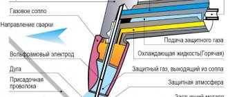
Basic and additional welding mode parameters
The main parameters of the manual arc welding mode are the diameter of the electrode, the strength of the welding current, as well as its type and polarity, arc voltage and welding speed.
Additional parameters include indicators such as the amount of sticking out of the electrode, the composition and thickness of the protective coating on it, the position of the electrode and the spatial arrangement of the welded joint (i.e. how welding is performed: welding vertical seams, welding horizontal seams, welding ceiling seams, etc.). d.).
Welding safety
The regulations establish the following rules:
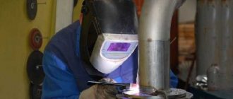
- The welder puts on a special suit, gloves made of spark-resistant material, and closed shoes with rubber soles. They protect the skin from splashes of molten metal and harsh ultraviolet radiation from the arc. The face is covered with a mask with dark glass. Eyes must be protected not only from direct ultraviolet rays, but also from side glare (reflections from walls).
- The post is equipped with a hood. If work is carried out in the field or installation conditions, ventilation will be organized. If this is not possible, the welder works in a respirator. Electrodes with an acidic coating are the most toxic. Instead, it is recommended to use rutile acid.
- If there are people near the post, the master loudly pronounces the word “eyes” immediately before lighting the arc. So he warns them about the need to turn away or protect their eyesight.
- When performing work at height, use a mounting belt and other safety equipment.
- Comply with electrical safety requirements.
The last item includes the following settings:
- Before starting work, check the integrity of the insulation of cables and other live parts. If there are ruptures, crumbled areas and other defects, it is prohibited to use the device.
- If it is necessary to repair, replace consumables, move, or during downtime or a lunch break, the equipment is de-energized.
- The connection to the network is made through a circuit breaker that protects against short circuits.
- Welding in conditions of high humidity (in a boiler room, cooling tower, basement or outdoors during rain) should be carried out by a welder with the appropriate skills.
The welder puts on gloves and a special suit.
What is the influence of welding current?
This value determines the amount of heat released: Q=(I^2)*R,
Recommended reading: Why do you need a welding log?
Where:
I – amperage;
R – arc resistance.
Thus, the depth of metal melting depends on this parameter. If you choose it too low, the seam will be weak and there will be uncooked areas.
Excessive amperage leads to through burning of the workpiece with subsequent leakage of metal from the weld pool.
What does the parameter depend on?
To select the correct current value for welding, it is necessary to take into account a number of factors. To understand their role, each should be considered in detail.
Electrode thickness
The most important criterion. As the diameter of the consumable increases, the amperage increases. The average ratio is 30 A per 1 mm.
The thickness of the electrode affects the amount of current for welding.
On the packaging with consumables, the recommended current is indicated as a range, for example, 80-120 A. The technician selects the exact value experimentally.
Sheet metal thickness
This indicator influences the choice of consumables. As the thickness of the metal increases, the diameter of the rod increases. The amperage increases accordingly. This is because more heat is required to melt the edges of massive workpieces.
The actual size of the part must be taken into account. If the edges were cut, i.e. chamfers were cut from them, then their thickness in the joint area will be less. The current is reduced accordingly.
Seam characteristics
There are 2 welding methods:
- Single pass.
- Multilayer.
The second type is used to connect parts of large thickness. Each layer uses its own consumable diameter and amperage. The root part is boiled with a 3 mm electrode, then thicker rods are used.
The choice of current strength is influenced by the spatial position of the seam. Depending on this, the manufacturer’s recommended value is used:
- Lower – 100% of the manufacturer’s recommended value.
- Vertical – 85-90%.
- Ceiling – 75%.
The choice of current strength is influenced by the position of the seam.
In the latter case, consumables with a diameter of no more than 4 mm are used.
Current polarity
When welding with direct current, there are 2 types of polarity:
1 Direct. The negative pole of the source is connected to the consumable.
2 Reverse. “Minus” is connected to one of the blanks.
The temperature distribution in the arc depends on the polarity. Taking this into account, the amperage is adjusted.
Welding arc length
To achieve a good connection, it is important to correctly determine not only the diameter of the welding electrodes, but also the length of the welding arc. There is a common belief among welders that the length of the arc should correspond to the diameter of the electrode used. However, it is very difficult for novice electric welders to maintain such a short arc without it being pulled to the side.
Therefore, when selecting this value, you should proceed from the current strength and diameter of the electrodes used for welding:
- For electrodes up to 2 mm - the arc length is 2-2.5 mm;
- For 3 mm electrodes, the arc length is 3.5 mm;
- For 4 mm electrodes, the arc length is 4.5 mm;
- For 5 mm electrodes, the arc length is maintained within 5.5 mm.
In addition, it is important to take into account the optimal welding speed, which also largely depends on the current strength and other features. Here you can follow one proven path, and with the correct selection of welding speed, the welding seam should be approximately twice the diameter of the electrode used.
Universal table for determining current strength
It is convenient to present the dependence of the amperage and diameter of the consumable on the thickness of the workpiece in tabular form. In this case, the relative position of the parts is taken into account.
For butt joints
The surfaces to be welded are located parallel to each other. Set the following amperage:
| Edge thickness, mm | Consumable diameter, mm | Amperage, A |
| 1,5-2,0 | 1,6-2,0 | 30-45 |
| 3 | 3 | 65-100 |
| 4-8 | 4 | 120-200 |
| 9-12 | 4-5 | 150-200 |
| 13-15 | 5 | 160-250 |
| 16-20 | 6-8 | 200-350 |
| Over 20 | 6-8 | 200-350 |
For corner and T-joints
The surfaces of the workpieces are located perpendicularly. The cross section of the surfacing has the form of a right triangle with a convex hypotenuse. The amperage is set in accordance with the table:
| Seam leg, mm | Consumable diameter, mm | Amperage |
| 3 | 3,0 | 65-100 |
| 4-5 | 4,0 | 120-200 |
| 6-9 | 5,0 | 160-250 |
More information about choosing current for electrode welding in practice
Recommendations from experienced welders will help you find the optimal value.
Influence of welding mode
The parameters that regulate the process are divided into basic and additional. The first group includes:
- speed of movement of the consumable;
- its diameter;
- arc voltage;
- type, polarity and current.
We recommend reading Reinforcement welding technology
Arc voltage, polarity and current control the welding process.
Additional options are:
- position of the consumable;
- composition and thickness of its coating;
- part orientation.
All of these factors are called welding mode. They are interconnected: a change in one value entails a correction in the other. For example, if you need to reduce heat input, you can do it in 2 ways:
- Reduce amperage.
- Increase the speed of movement of the consumable.
This relationship is taken into account and, if necessary, productivity is increased. Set the speed to a higher speed while simultaneously increasing the amperage.
It is impossible to evaluate the influence of each factor mathematically and derive the corresponding formulas. In each case, it is important to adapt and select the optimal amperage experimentally.
Arc length
There is a linear relationship between arc length and arc voltage. As the first indicator increases, so does the second. In this case, the current strength and heat generation change little.
Arc length affects voltage.
As the length of the arc increases, the quality of the seam decreases. The reasons are as follows:
- The discharge “walks” along the surface, as a result of which heat spreads over a large area. Accordingly, the edges in the joint zone warm up worse.
- The molten metal from the consumable rod bounces off the poorly heated surface. Spattering increases and the seam becomes dirty. Only part of the alloying elements enters the weld pool.
The optimal arc length in mm is determined by the formula L=d+0.5, where d is the electrode diameter in mm.
The melting consumable is gradually shortened during operation, so the holder is gradually brought closer to the workpiece.
Forward or reverse polarity
When welding with direct current in an arc, 2 zones are distinguished:
- Anode spot. Located on the positive pole side of the source.
- Cathode. It is located on the minus side.
The zones have different temperatures. When using a consumable electrode, the anode spot is colder than the cathode spot, so to connect thin-walled workpieces proceed as follows:
- “Plus” is connected to the part being welded (straight polarity).
- Set the minimum current from the recommended range.
In the argon arc method, direct polarity is used.
This prevents burning of the workpieces.
To connect thick-walled parts, strong heating is required. For this:
- A “minus” is connected to them (reverse polarity when welding).
- Set the maximum amperage from the proposed range.
This ensures deep penetration, making the connection strong and reliable.
When using a refractory electrode (argon-arc method), an inverse temperature distribution is observed: the anode spot is hotter. This technology provides only direct polarity, since in reverse the arc hits the consumable and it quickly becomes clogged. When connecting thin-walled parts, heat input is controlled by amperage and welding speed.
Electrode coating
Based on their composition, there are 4 types of coating:
- Rutile.
- Main.
- Cellulose.
- Sour.
The electrode coating can be rutile.
The main coating differs from the others in the presence of a deionizing element - fluorine. It reduces the number of charge carriers, which makes arcing more difficult. To stabilize this process, it is necessary to increase the amperage by 20-30 A. So, if for welding with a rutile consumable with a diameter of 2 mm, the device is set to 40-70 A, then for the main consumable of the same thickness - to 60-100 A.
Direct and alternating current
The type of current does not affect the amperage. It is selected according to the following criteria:
- If high demands are placed on the quality and strength of the seam, constant tension is used. It is characterized by slight arc deflection and weak metal spattering. The seam turns out smooth and clean. On direct current, the arc burns better; it is possible to regulate the temperature distribution by changing the polarity. This is used when working with thin-walled workpieces and non-ferrous metals.
- If the requirements for the quality and strength of the connection are low, alternating voltage is used. It allows you to reduce costs, because equipment for this type of welding costs 1.5 times less. It is also smaller in size and weight.
We recommend reading: How to weld heating pipes using electric welding
In addition, preference is given to alternating current in the following cases:
- The workpiece material contains oxides. Frequent changes in the direction of current contribute to their greater destruction. For example, aluminum is welded using alternating voltage, because an oxide film forms on its surface.
- The surface of the part is so dirty that it cannot be cleaned.
With constant current, the seam is smooth.
When choosing the type of voltage, the coating material of the consumable is also taken into account. On electrodes with a basic coating, the arc burns worse due to the deionizing effect of fluorine, so they can only be welded with direct current. For other varieties, any genus is suitable.
Features for inverters
The main difference between devices of this type is the presence of a special electronic unit that increases the frequency of the mains current to tens of kHz. This gives the following result:
- The size and weight of the transformer are reduced.
- Its efficiency increases.
- The price is reduced (due to reduced material consumption).
Electronic control makes it easy to adjust the current strength. It is set by a switch on the inverter, and the device selects the voltage automatically. Models with smooth adjustment are the most convenient to use.
The electronics independently adjusts the amperage when:
- Arc ignition. The function is called “Hot Start” or Hot Start. The current briefly increases by 5-100% of the rated current, which facilitates the occurrence of an arc discharge. On cheap models, the manufacturer sets the excess value at its discretion, and it cannot be changed. On expensive ones, the parameter is set by the user. The function is in demand when welding with poor consumables, the presence of rust and scale on parts, and unstable voltage in the network.
- Breaking the arc or connecting the electrode to the workpiece using a drop of molten metal (the consumable is welded). A surge of current also occurs. This promotes the resumption of discharge combustion or the separation of a drop from the rod. The function is called Arc Force.
- Touching the workpiece with the rod. The amperage is reset, which allows you to tear off the consumable. The name of the function is “Antistick”.
The required mode for welding with an inverter is selected taking into account its power. Many models belong to the household class and are not designed for high currents. The maximum diameter of the consumable for them often does not exceed 2 mm, the recommended amperage is 30-45 A.
Selecting the manual arc welding mode
Arc welding is controlled by a number of parameters, namely:
- welding current
- arc voltage
- welding speed
- type and polarity of current
- position of the seam in space
- electrode type and diameter
Therefore, before starting work, you should select the values of these parameters so that the welding seam is of the required size and of good quality.
1.1 Welding current (selection of welding current by selecting the electrode diameter)
The most important parameter when working with manual arc welding is the strength of the welding current. It is the welding current that will determine the quality of the weld and welding performance in general.
Typically, recommendations for choosing the welding current are given in the user manual that comes with the welding machine. If there is no such instruction, then the strength of the welding current can be selected depending on the diameter of the electrode. Most electrode manufacturers place information about welding current values directly on the packaging of their products.
The diameter of the electrode is selected depending on the thickness of the product being welded. However, remember that increasing the diameter of the electrode reduces the welding current density, which leads to wandering of the welding arc, its fluctuations and changes in length. As a result, the width of the weld seam increases and the depth of penetration decreases - that is, the quality of welding deteriorates. In addition, the level of welding current depends on the location of the weld in space. When welding seams in an overhead or vertical position, it is recommended that the diameter of the electrodes be at least 4 mm and the welding current reduced by 10-20%, relative to standard current values when working in a horizontal position.
Table 1.1
| Approximate ratio of metal thickness, electrode diameter and welding current | ||||||||
| Metal thickness, mm | 0,5 | 1-2 | 3 | 4-5 | 6-8 | 9-12 | 13-15 | 16 |
| Electrode diameter, mm | 1 | 1,5-2 | 3 | 3-4 | 4 | 4-5 | 5 | 6-8 |
| Welding current, A | 10-20 | 30-45 | 65-100 | 100-160 | 120-200 | 150-200 | 200-250 | 200-350 |
1.2 Arc voltage (welding arc length)
After the welding current has been determined, the length of the welding arc should be calculated. The distance between the end of the electrode and the surface of the work being welded determines the length of the welding arc. Stable maintenance of the length of the welding arc is very important when welding, this greatly affects the quality of the welded seam. It is best to use a short arc, i.e. the length of which does not exceed the diameter of the electrode, but this is quite difficult to implement even with solid experience. Therefore, the optimal arc length is considered to be the size that is between the minimum value of a short arc and the maximum value (exceeds the electrode diameter by 1-2 mm)
Table 1.2
| Approximate ratio of electrode diameter to arc length | ||||||||
| Electrode diameter, mm | 1 | 1,5-2 | 3 | 3-4 | 4 | 4-5 | 5 | 6-8 |
| Arc length, mm | 0,6 | 2,5 | 3,5 | 4 | 4,5 | 5 | 5,5 | 6,5 |
1.3 Welding speed
The choice of welding speed depends on the thickness of the product being welded and the thickness of the weld seam. The welding speed should be selected so that the weld pool is filled with liquid metal from the electrode and rises above the surface of the edges with a smooth transition to the base metal of the product without sagging or undercuts. It is advisable to maintain the advance speed so that the width of the weld seam is 1.5-2 times greater than the diameter of the electrode.
If you move the electrode too slowly, a fairly large amount of liquid metal is formed along the joint, which spreads in front of the welding arc and prevents it from affecting the welded edges - that is, the result will be lack of penetration and a poorly formed seam.
Unreasonably fast movement of the electrode can also cause lack of penetration due to insufficient heat in the working area. And this is fraught with deformation of the seams after cooling, up to cracks.
The simplest method for selecting welding speed is based on approximately the average size of the weld pool. In most cases, the weld pool has the following dimensions: width 8–15 mm, depth up to 6 mm, length 10–30 mm. It is important to ensure that the weld pool is evenly filled with molten metal, because the penetration depth remains almost unchanged.
The figure shows that as the speed increases, the width of the weld noticeably decreases, while the penetration depth remains almost unchanged. Obviously, the highest quality seams (in this example) are at speeds of 30 and 40 m/h.
1.4 Type and polarity of current
For most models of household machines for manual arc welding, a direct welding current is generated at the output by rectifying the alternating current. When using direct current, there are two options for connecting the electrode and the part:
- With direct polarity, the part is connected to the “+” terminal, and the electrode to the “-” terminal
- With reverse polarity, the part is connected to “-”, and the electrode to “+”
The positive pole generates more heat than the negative pole. Therefore, reverse polarity when working with electrodes is used when welding thin sheet metal, so as not to burn it. You can use reverse polarity when welding high-alloy steels to avoid overheating, but with direct polarity it is better to weld massive parts
| D.C | |
| Straight polarity | Reverse polarity |
|
|
Low-alloy steels are structural steels that contain no more than 2.5% alloying elements (carbon, chromium, manganese, nickel, etc., and carbon should not be more than 0.2%); they are widely used in construction and shipbuilding , pipe rolling production. Welding of low-alloy steels can be done either manually or automatically, regardless of the polarity of the current.
1.5 Ignition (excitation) of the welding arc
Ignition (excitation) of the welding arc can be done in 2 ways.
| First method: We strike the end of the electrode on the surface of the metal (reminiscent of the movement of a lit match). This method is most often used on a new electrode. This method is simple and does not require any special professional skills. | The second method can be called “touch”, because the electrode is brought vertically (perpendicularly) to the place where welding begins and, after lightly touching the surface of the product, the top is pulled back to a distance of approximately 3-5 mm. Most often, this method is used in hard-to-reach, narrow and other inconvenient places. |
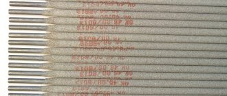
Does the electrode brand affect the choice of current strength?
The composition of the coating is determined by the brand. For example, Uoni-13 and TsU-5 consumables have a basic type of coating. They provide high quality and strength of the weld due to the absence of hydrogen in the metal, but burn worse than others. Therefore, they are welded only at constant voltage, the amperage is increased by 20-30 A. Other consumables are not so demanding on the welding mode.
Recommended parameters for all products are indicated on the packaging.
Knowing how to select the welding current, the master will perform the job efficiently with any electrode and in all spatial positions.
Power supplies
Currently, according to the type of electricity, welding with alternating and direct current can be used. It is important not only to choose the right welding mode and electrode thickness, but also to select the right power source. Let's look at the most common sources of welding current and find out what their differences are:
Welding transformers
They create welding current simply by lowering the mains voltage. This determines
x good reliability and low cost. AC welding using transformers is best suited for working with low-carbon steels. A huge drawback is its heavy weight and huge energy consumption, which is detrimental to conventional electrical networks. When the voltage decreases to 160-180 V, these power supplies do not work.
Welding rectifiers
Converts mains voltage with further rectification using diode or thyristor blocks. These power supplies are very simple and highly reliable. They are used for welding virtually any steels and alloys using various types of electrodes. When working with this welding, the formation of metal spatter occurs in less than an hour.
We eat at the transformer, while better arc burning and its stability are noticed, so the weld is better. Its energy costs are higher than those of a transformer, since a certain amount of energy is lost on the diode unit. It is also impossible to operate this device in places where the voltage can drop to 180 volts.
Welding inverters
Their principle is based on the conversion of alternating current at the input of the device into direct current, then, using transistor switches, the direct current is converted into alternating current with a frequency above 50 kHz and is supplied to a high-frequency transformer with subsequent rectification. Data
power supplies have perfect output pulse characteristics suitable for various types of welding. The rectifier has low power consumption and high efficiency (more than 85%), due to which the load on the network is reduced many times. The device is equipped with a variety of functions such as easy arc formation, non-sticking electrodes, “hot start”, etc. The inverter can work with any types of electrodes and all grades of steel.