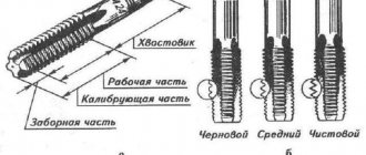
A die is a special metal-cutting tool designed for creating external threads or for calibrating them on cylindrical workpieces. In addition to manual cutting, a lerka (this is another name for a die) can be used as equipment with which machine cutting is performed. To do this, it is installed on metal-cutting machines, for example, drilling or lathes. The simplicity of the die design, combined with its versatility, makes it possible to use it in serial industrial production, as well as in everyday life, where one-time work is usually performed.
MAIN DIMENSIONS AND THREAD PROFILE
1. MAIN DIMENSIONS AND THREAD PROFILE
1.1. The main dimensions and thread profile of the taps must correspond to those indicated in Figure 1 and in Tables 1 and 2.
Damn.1. Thread profile of taps for conical inch threads with a profile angle of 60° according to GOST 6111; Thread profile of taps for conical pipe threads with a profile angle of 55° according to GOST 6211
Thread profile of taps for tapered inch threads with a profile angle of 60°
GOST 6111
Thread profile of taps for pipe tapered threads with a profile angle of 55°
GOST 6211
____________ *Size for reference.
Damn.1
Notes:
1. The bisector of the profile angle is perpendicular to the axis of the tap.
2. The thread pitch is measured parallel to the axis of the tap.
3. Maximum deviations of thread profile dimensions must be measured from the lines of the theoretical profile in the direction perpendicular to the axis of the tap.
Tapers for tapered inch threads according to
GOST 6111 Dimensions in mm
Table 1
| Tap designation | Applicability | Thread size designation | Number of steps per length 25.4 mm | (limit deviation ±0.013 at length up to 25 mm) | Maximum angle deviations | |||||||||||||
| No-min. | Prev. off For | Prev. off For | half the profile angle | inclination angle | ||||||||||||||
| 2680-0001 | 27 | 0,941 | 50 | 16 | 10 | 2,8 | 15 | 8,3 | 7,142 | 6,3 | 5,5 | 5,7 | 0,377 | -0,035 | -0,045 | 4,5 | ±30′ | -6′ +3′ |
| 2680-0002 | 16 | 8,0 | 7 | |||||||||||||||
| 2680-0003 | 55 | 18 | 11 | 10,7 | 9,519 | 8,0 | 8,0 | |||||||||||
| 2680-0004 | 19 | 11,2 | 10 | |||||||||||||||
| 2680-0005 | 18 | 1,411 | 65 | 24 | 15 | 4,2 | 14,1 | 12,443 | 11,2 | 10,3 | 0,565 | -0,040 | -0,065 | ±25′ | -5′ +3′ | |||
| 2680-0006 | 22 | 14,0 | 12 | |||||||||||||||
| 2680-0007 | 75 | 26 | 16 | 17,7 | 15,926 | 13,8 | ||||||||||||
| 2680-0008 | 14 | 1,814 | 85 | 30 | 21 | 5,5 | 26 | 21,8 | 19,772 | 18,0 | 16 | 17,0 | 0,726 | -0,050 | -0,085 | 6 | ±20′ | |
| 2680-0009 | 95 | 32 | 21 | 32 | 27,3 | 25,117 | 22,4 | 20 | 22,3 | |||||||||
| 2680-0010 | 2,209 | 110 | 40 | 26 | 6,6 | 36 | 34,1 | 31,461 | 28,0 | 25 | 28,0 | 0,884 | ||||||
| 2680-0011 | 120 | 42 | 27 | 40 | 42,9 | 40,218 | 31,5 | 29 | 36,7 | |||||||||
| 2680-0012 | 140 | 45 | 49,0 | 46,287 | 35,5 | 33 | 42,8 | |||||||||||
| 2680-0013 | 45 | 28 | 52 | 61,2 | 58,325 | 45,0 | 42 | 54,8 | ||||||||||
An example of a symbol for cutting a tapered inch thread with a shank diameter of 14 mm:
Tap 2680-0006 GOST 6227
Taps for tapered pipe threads according to
GOST 6211 Dimensions in mm
table 2
| Maximum angle deviations | |||||||||||||||||
| Tap designation | Applicability | Thread size designation | Number of steps per length 25.4 mm | (limit deviation ±0.013 at length up to 25 mm) | (limit off: peaks +0.015 -0.025; troughs +0.050) | half profile angle | inclination angle | ||||||||||
| 2680-0051 | 28 | 0,907 | 52 | 14 | 10,1 | 2,7 | 13 | 7,9 | 7,142 | 5,6 | 5 | 5,7 | 0,145 | 0,125 | 4,5 | ±25′ | -6′ +3′ |
| 2680-0014 | 59 | 15 | 10,1 | 16 | 10,0 | 9,147 | 8,0 | 7 | 7,7 | ||||||||
| 2680-0016 | 19 | 1,337 | 67 | 19 | 15,0 | 4,0 | 18 | 13,4 | 12,301 | 10,0 | 9 | 10,3 | 0,214 | 0,184 | ±20′ | ||
| 2680-0018 | 75 | 21 | 15,4 | 20 | 17,0 | 15,806 | 12,5 | 11 | 13,6 | 6 | |||||||
| 2680-0019 | 14 | 1,814 | 87 | 26 | 20,5 | 5,5 | 24 | 21,3 | 19,793 | 16,0 | 14 | 17,0 | 0,290 | 0,249 | |||
| 2680-0020 | 96 | 28 | 21,8 | 28 | 26,8 | 25,279 | 20,0 | 18 | 22,4 | ||||||||
| 2680-0021 | 11 | 2,309 | 109 | 33 | 26,0 | 7,0 | 34 | 33,7 | 31,770 | 25,0 | 22 | 28,3 | 0,369 | 0,317 | ±15′ | -5′ +3′ | |
| 2680-0022 | 119 | 36 | 28,3 | 40 | 42,4 | 40,431 | 31,5 | 29 | 36,8 | ||||||||
| 2680-0023 | 125 | 37 | 28,3 | 45 | 48,3 | 46,324 | 35,5 | 33 | 42,6 | ||||||||
| 2680-0024 | 140 | 41 | 32,7 | 48 | 60,1 | 58,135 | 40,0 | 37 | 54,3 | ||||||||
An example of a symbol for cutting a tapered pipe thread:
Tap 2680-0016 GOST 6227
(Changed edition, Amendment No. 1, 2).
1.2. The dimensions of the squares are according to GOST 9523.
1.3. For thread taps, ; , ; , it is allowed to make a groove to exit the wheel when grinding threads. (Changed edition, Amendment No. 1).
1.4. Center holes are form A according to GOST 14034. Thread taps can be manufactured with external centers. (Changed edition, Amendment No. 1, 2).
1.5. Rounding along the top and bottom of the profile of a conical inch thread is allowed within the tolerance range of .
1.6. Structural elements and geometric parameters of taps are indicated in Appendix 1.
TECHNICAL REQUIREMENTS
2.1. Taps must be manufactured in accordance with the requirements of this standard according to working drawings approved in the prescribed manner.
2.2. Taps must be made of high-speed steel in accordance with GOST 19265.
2.3. Taps for threads and more must be made welded. Taps for threading can be made welded. In the welding zone, shells, lack of penetration, arson of metal, ring cracks and fistulas are not allowed.
2.4. The shanks of welding taps must be made of steel grade 45 according to GOST 1050 or steel grade 40X according to GOST 4543.
2.5. The hardness of the taps should be:
| working part | — 63…66 HRC; |
| for high-speed steel taps with a vanadium content of 3% or more and cobalt content of 5% or more | — 64…68 HRC; |
| shank over a length including a square and an annular groove: | |
| at welding taps | — 37…52 HRC; |
| for solid taps | — 37…57 HRC. |
(Changed edition, Amendment No. 1).
2.6. Taps can be made cyanidated.
2.7. The roughness parameters of tap surfaces according to GOST 2789 should not be more than, microns:
| thread profile, front and back surface | 3,2 |
| shank (in the landing part) | 0,8 |
| grooves | 10 |
| other surfaces | 25 |
Note. The roughness parameter of the front surface must be maintained at a height not less than the height of the thread profile. A fracture of the front surface towards the undercut is allowed. (Changed edition, Amendment No. 1).
2.8. After heat treatment, the center holes and outer centers must be machined. (Changed edition, Amendment No. 2).
2.9. The taps must be backed up along the profile along the entire length of the working part and along the outer surface of the intake cone.
2.10. By agreement with the consumer, it is possible to produce taps without annular grooves.
2.11. Maximum deviations of tap sizes should not be more than:
| total length | 16 |
| working part length | 216 |
| fence length | plus thread pitch |
| length to main plane | ± thread pitch |
| length | 15 |
| shank diameter | 9 |
| diameter of ring grooves | 14 |
| radius of annular grooves | 16 |
| front corner | ±2° |
| rear angle along the cutting (taking) part for threads: | |
| from to | ±1°30′ |
| from to | ±1°. |
2.12. (Deleted, Amendment No. 1).
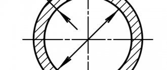
2.13. The radial runout tolerances of the cutting part, calibrating part and shank must correspond to those indicated in Figure 2 and Table 3.
Damn.2. Tolerances for radial runout of the cutting part, gauge part and shank
Damn.2
Table 3
Dimensions in mm
| Thread size designation | |||
| -, | 0,03 | 0,02 | 0,02 |
| — | |||
| , | 0,03 | ||
| -, — | 0,04 | 0,03 |
(Changed edition, Amendment No. 1).
2.14. The average time to failure and 95% operating time of taps made of R6M5 steel must be no less than the values indicated in Table 3a.
Table 3a
| Thread size designation | Average time to failure, pcs. (number of holes cut) | 95% operating time, pcs. (number of holes cut) |
| , ; , | 185 | |
| 75 | , ;, | 225 |
| 90 | , ; , | 275 |
| 110 | , , , | 175 |
| 70 | , , , | 125 |
(Changed edition, Amendment No. 1, 2).
2.15. The criterion for taps becoming dull is that the thread being cut does not meet the required accuracy.
(Introduced additionally, Amendment No. 1).
2.16. The following must be clearly marked on the tap shank: the manufacturer's trademark; designation of the tap (last four digits); thread designation; steel grade of the working part. Notes:
1. It is permissible not to mark steel grade R6M5.
2. It is allowed to mark the letters instead of the steel grade: HSS - for steel with a tungsten content of 6% or more; HSSCo - for steel containing cobalt, indicating the steel grade on the label.
3. On thread taps -, - markings may be applied on a square.
4. On thread taps -, - the designation of the taps may not be marked.
2.17. Transport marking, marking of consumer containers and packaging - in accordance with GOST 18088.
2.16, 2.17. (Introduced additionally, Amendment No. 2).
Quality of the tools used
On sale you can find dies made from a wide variety of alloys. The following metals can be used in manufacturing:
- High-speed steel 9ХС and ХСС, Р6М5. Today it is found on sale more often than other steels. This is due to its exceptional performance and relatively low cost. Less commonly used is P18 steel, which was common at the time of the existence of the USSR.
- The quality of a tool largely depends on the precision of its production. If the shape accuracy is poor, or there are defects on the surface, then this indicates poor quality of the tool.
Read also: Vacuum rubber GOST 7889
The cost of the tool may depend on a fairly large number of factors. As a rule, instruments from foreign manufacturers are much more expensive than domestic ones.
ACCEPTANCE
3.1. Acceptance rules - according to GOST 23726. (Changed edition, Amendment No. 1).
3.1.1. Periodic tests for average time to failure are carried out once every three years, for 95% operating time - once a year on at least five taps.
3.1.2. Tests of taps must be carried out on one standard size for each range of threads indicated in Table 4.
Table 4
| Thread size designation | Cutting speed, m/min |
| -; — | 2,7-3,6 |
| -; — | 3,6-5,5 |
3.1.1, 3.1.2. (Changed edition, Amendment No. 1, 2).
CONTROL METHODS
4.1. Testing of taps must be carried out on drilling or threading machines that meet the standards of accuracy and rigidity established for them.
4.2. Fastening of taps should be carried out using cartridges that ensure self-alignment of the taps or product in the radial direction, compensating for deviation from the hole and tap.
4.3. Taps must be tested on samples made of steel grade 45 according to GOST 1050, hardness 197...207 HB.
4.4. For products intended for threading, the holes must be pre-processed with conical reamers with a conical shape of 1:16. The diameter of the machined hole must correspond to the internal diameter of the thread in accordance with GOST 6111 or the diameter of the holes for cutting conical pipe threads in accordance with GOST 21350.
4.1-4.4. (Changed edition, Amendment No. 1).
4.5. Tests of taps for performance, average time to failure and 95% operating time must be carried out under the modes specified in Table 4. (Changed edition, Amendment No. 1, 2).
4.6. Each test subject must use a tap to cut the number of holes indicated in Table 5.
Table 5
| Thread size designation | Number of holes cut |
| From to ; from to | 35 |
| And ; And | 25 |
| And ; And | 12 |
| From to ; from to | 10 |
After the performance test, the cutting edges should be free of chipping. After testing, taps must be suitable for further work.
4.7. A 5% (by weight) solution of emulsol in water with a flow rate of at least 5 l/min is used as a cutting fluid for machine thread cutting.
4.6, 4.7. (Changed edition, Amendment No. 1).
4.8. Acceptance values of mean time to failure and 95% operating time should not be less than those indicated in Table 6.
Table 6
| Thread size designation | Acceptance values of operating time, pcs. (number of holes cut) | |
| average | 95% | |
| , ; , | 210 | 85 |
| , ; , | 255 | 100 |
| , ; , | 310 | 125 |
| , ; , | 198 | 80 |
| , ; , | 140 | 55 |
(Changed edition, Amendment No. 1, 2).
4.9. The hardness of the taps is measured according to GOST 9013.
4.10. Appearance is controlled by inspection.
4.11. The surface roughness parameters of taps are checked by comparison with roughness samples in accordance with GOST 9378 or with standard tools having the values of surface roughness parameters specified in clause 2.7, using a magnifying glass LP-1-4 in accordance with GOST 25706.
4.12. When monitoring the parameters of taps, methods and measuring instruments must be used, the error of which does not exceed: when measuring linear dimensions - the values specified in GOST 8.051; when measuring angles - 35% of the tolerance value for the angle being tested; when monitoring the shape and location of surfaces - 25% of the tolerance value for the parameter being tested.
4.13. Compliance of the parameters of the cut thread with the requirements of clause 2.15 is controlled using conical thread gauges (plugs) in accordance with GOST 6485.
4.9-4.13. (Changed edition, Amendment No. 1).
How to cut threads using a groove
Before you start actually cutting the thread, you should chamfer the end of the workpiece at an angle of 45 degrees. This will make it easier to roll the first turns due to the ability to position the die so that its axis is strictly parallel to the axis of the workpiece. Then you should do the following:
- the workpiece is secured in a bench vice. In this case, it is necessary to control that its axis is oriented strictly vertically;
- the tool and workpiece are lubricated with technical oil;
- the die is applied to the end of the rod strictly horizontally;
- then several initial rotations of this tool are made;
- if in the first circles a clear distortion is noticed, you should remove the bench, tap the bar being processed and start working again;
- rotation of the tool at the beginning of the cutting procedure should be accompanied by uniform pressure on the handles of the die holder;
- Having created the first few turns, you should check the horizontality of the handle and the knob. To do this you need to use a level. If the tool is oriented correctly in space, thread cutting continues along the entire length of the workpiece;
- Having made one or two turns to remove the chips, you need to turn the blade in the opposite direction half a turn;
- when approximately the middle of the piece of workpiece on which the thread is cut is reached, the pressing force can be weakened due to the start of the self-tightening process;
- Having completed the cutting, the tool should simply be returned to its original position along the thread made and removed from the workpiece.
Checking the correctness of the work performed is carried out using special templates, calipers, or by screwing on a nut of the appropriate size.