DIY Telwin 165 inverter repair
In this article, we will slightly lift the curtain on the everyday life of a regular service center for the repair of welding equipment. Today we present to your attention the repair of the Telwin Force 165 welding inverter. Perhaps, after reading the information provided, you will be able to fix some problems yourself. And remember, do not undertake repairs if you are not confident in your actions, as a result, it will always be expensive.
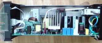
No matter how trite it sounds, repairs begin with disassembling the device. First, remove the handle, which is secured with 4 screws. Then unscrew 2 screws located on the plastic part (holding the front and back panels) and 2 screws that secure the case on the sides). Also, be sure to remove the current control knob by pulling it towards you, because it will prevent the front panel of the inverter from being separated from the overall body.
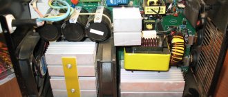
Diagnostics begins with a superficial inspection of the board. You need to look carefully to see if there are any burnt out tracks, damaged elements, or the like. A quick inspection immediately shows that the charging resistor, which is responsible for the smooth charging of the capacitors, has failed.
Without it there will be a big hit to the network. The fact that the charging capacitor has burned out indicates 3 things:
- Broken diode bridge
- Electrolytic capacitors are broken;
- Power switches – IGBT transistors.
Let's start calling
It is better to start testing from the output terminals, this way the suitability of the output diode bridge is checked.
Then they check
- input bridge on the back of the board;
- diode bridge for short circuit;
- high side capacitors;
- IGBT power transistors need to be measured between the drain and source, that is, between the collector and emitter.
In this particular case of Telwin Force 165 repair, it was the transistors that failed.
Usually, when transistors burn out, drivers also burn out. In this case, the transistors need to be removed. After dismantling the transistors, you need to check the serviceability of the drivers. To do this, find resistances of 15 ohms and ring them in the tester's dialing mode. If they are intact, there is a high probability that the driver is good. If these resistors are broken, then you will have to completely check the driver. Diodes and transistors are located nearby; they are checked for breakdown.
Before turning it on, you need to make sure that there is no short circuit at high (that the short circuit was actually in the transistors). We check on capacitors.
The topology of this inverter, Telwin 165, is an oblique half-bridge. The output transformer is connected between the transistors. Why is it called that, an oblique half-bridge? The transistors are turned on as if obliquely. The other oblique arm of the bridge contains discharge diodes. They need to be called in advance, because when transistors break down, very often these diodes also break down.
Suppressors - transistor snubbers - are also checked. They rarely fly out.
If there is no short circuit, you need to apply power and use an oscilloscope to see what signal is received by the transistors. Many repairmen look at the waveforms on the gates, but we recommend soldering a 220 -1000 pF capacitor from the emitter to the gate. This simulates gate capacitance and loads the driver circuit. So the entire output transistor driver thinks it is driving the transistor's gate. The oscillogram will be approximately the same as when working with a real transistor. Without load everything can show well, under load we will see what the shape will be.
Before connecting the power, you will definitely need a hundred-watt light bulb with two wires. Unless you are an experienced repairman, you will need to trim the trace on the board. The fact is that you may not notice a shorted transformer, a broken snubber, diodes, etc. Cutting the supply path will save you from costly failure of all power.
After any manipulation, when you turned on the power and then turned it off, you need to discharge the capacitors on the light bulb. The voltage on them is lethal, 310V, it can even be fatal.
During the adjustment process, a light bulb is soldered between the two cut tracks, which limits the current flowing through the output part. And even if something is wrong somewhere (the frequency is too low, transformers are broken, the output is broken, etc.), the light bulb will simply light up at full intensity, and everything else will remain intact.
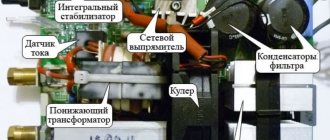
In the Telwin Force 165, the circuit is constructed as follows: as such, there is no control room, but... through a resistor, the mains voltage (310V) charges the capacitors, which feed the PWM and it tries to start the power part with short pulses. At the moment the power section is started, the tap from the power transformer, through a diode and crank, begins to power the entire circuit. The entire circuit “starts up” - at this moment the relay clicks and the fan turns on. In this way, the inverter is started, i.e. it operates on self-feeding (not from the duty room). If you turned on the inverter and the relay clicked, the fan rotated - this means that the power “started up”.
In the specific board under consideration, when power is applied, there should be short “packs” of pulses at the pins shown in the photo between the emitter and the gate - startup attempts - approximately once every second.
To check, you need to solder the negative probe of the oscilloscope to the emitter.
Important point! The voltage you supply must be galvanically isolated from the mains so that the oscilloscope and all other devices you connect do not fall under the phase (including the person who is repairing the inverter).
Another oscilloscope probe is placed on the gate and power is applied.
A series of trigger pulses should appear on the oscilloscope screen. This means that the driver, the TGR, and the transistor that controls the TGR are all in working order.
Then, the power is turned off, the capacitors on the light bulb are discharged and a switch is made to the other arm.
The impulses on the other shoulder are checked. Using an oscilloscope, you can measure the peak-to-peak and calculate their duration.
We solder the entire final cascade and try to start it, because everything is working as normal, as evidenced by the test described.
When installing new power IGBT transistors, all surfaces of the aluminum radiators to which they will be adjacent must be perfectly clean: cleaned of any contaminants and washed with alcohol.
Run your finger over the radiator where the transistors are installed: there should be no inclusions, the holes for the threads should not be burred and should not rise (when a screw is unscrewed, it is as if they are “pulling out” the threads from aluminum - you get a bump).
You need to make sure that there are no inclusions on the IGBT transistors, because any grain of sand will create a gap between the transistor and the heatsink, and accordingly, the heat sink function will not be fully performed.
KPT-8 paste ( Organosilicon Paste Teploconductive ) GOST 19783-74, used to improve heat transfer between powerful electronic components and the radiator, must be applied to the transistor exclusively from a tube . There is no need to scoop the paste out of the jars with spatulas.
The paste should be spread in as small a layer as possible and only on the metal part. When tightening the transistor, it should barely come out from under the housing. A thick layer leads to deformation of the transistor.
Radiators with transistors are installed back on the board and sealed. A light bulb is soldered into the technological section of the board track, which was mentioned earlier, and then power is supplied. The relay should click and the fan should turn on, this means that the power unit has started. If the light does not light, this indicates that everything is working normally and the quiescent current is normal.
We need to check the exit. Voltage should appear at the inverter output terminals. Carry out all work very carefully, because at the time of testing the circuit is under a high voltage of 310V DC!
A small 40 W light bulb is connected to the output terminals and if everything is normal, it should light up - the power part is in working order.
Next, the board is washed with isopropyl alcohol to remove the soldering flux, the “broken” track is restored and loaded onto the rheostat (the output current is checked).
The current regulator is set to minimum and a rheostat is connected. The probes are installed and the idle voltage is removed. The load is connected and the current is adjusted using the inverter handle. In this particular case of repair, the current was not regulated, i.e. was constantly at its maximum value. If the load were not a rheostat, but a real welding electrode, at the first contact with the metal with this electrode, the entire power part would burn out again, since the inverter constantly operates at its maximum power! It turns out that the original problem that led to the breakdown was the lack of current regulation. This suggests that the fault is somewhere in the master oscillator. The effect of the knocked-out force has already been repaired, but the cause needs to be looked for.
The transformer through which the primary winding of the power transformer passes is responsible for regulating the current. It is necessary to check the integrity of the secondary winding of this control transformer. The LM324 opamp makes a comparison between the set position of the current control knob in one arm and the data obtained from the trance shown in the photo in the other arm.
The results obtained by the op-amp are fed to the PWM microcircuit (the master oscillator for the operation of the entire power section) and the output current depends on the duration of its pulses. The duration of the pulses is set by the operating microcircuit based on the data received between the installed handle and what came from the transformer. In this case of repair, this scheme does not work. The reason needs to be established.
By replacing the LM324 comparator chip, the problem was solved and the inverter repair was completed. Further tests on the rheostat showed that the device is fully operational, and the current adjustment knob works as it should.
Source: Powerful Electronics
Schemes of welding machines and inverters
Photos of the internals, as well as the power electrical circuit of the inverter welding source PICO-160 Operating instructions and photographs of the Chinese inverter welding source MAXPOWER WT-180S
Schematic diagram of the LISA-12 feeding mechanism from KEMPPI
Hand-drawn diagrams of the PDG-101 U3.1 source, intended for semi-automatic welding in a shielding gas environment. The source can also be used as a booster charger
Passport for ARC FIRTER VIR-101 UZ
Operating manual and diagrams of semi-automatic welding machine PYTHON (PDG-15-3U3, PDG-20-3U3 380V)
Operating manual for oscillator OSPPZ-300 M1
Schematic electrical diagram of the power part and control unit of a single-phase version of the PULSAR semiautomatic device
Hand-drawn diagrams of an Alpha Technologies uninterruptible power supply (UPS) with sine wave output voltage. The source converter uses a ferroresonant stabilizing transformer (FST), which makes it possible to quite simply generate a stabilized sinusoidal voltage without the formation of a multi-pulse voltage modulated according to the sinusoidal law.
Technical description and operating instructions for welding source VDU-506
Technical description and operating instructions for the semi-automatic welding machine PULSAR
Operating manual (English) inverter welding source, ThermalArc model 250S DC CC, Thermadyne Company. Compared to ThermalArc model 160S, this version is more powerful and is powered by a three-phase network. The manual shows the functional and power diagrams of the source. The power circuit is interesting in that it uses two half-bridge converters (each with its own transformer) connected in series. Current-voltage characteristics are given.
Operating manual (English) for inverter welding source, ThermalArc model 160S DC CC, from Thermadyne Company. The manual shows the functional and power diagrams of the source. The power circuit is interesting in that it uses a half-bridge converter and a mains rectifier with voltage doubling. Current-voltage characteristics are given. When the output voltage is less than 10V, in TIG mode, the internal resistance of the source becomes negative, thereby reducing the erosion of the tungsten electrode during a short circuit.
Operating instructions for the inverter welding source Invertec V100 & V130 (English) from the well-known company Lincoln Electric, which, among other things, shows the power electrical circuit of the source
Description of the universal welding installation UDGU-301. The installation is intended for manual argon-arc welding with a non-consumable electrode on direct and alternating current (Rus.)
Schematic electrical diagram of the universal welding installation MARC 500 HF mig from the Finnish company KEMMPI. The installation is designed for manual argon-arc welding with a non-consumable electrode on direct and alternating current
Schematic diagram of the universal oscillator LHF500 from the Finnish company KEMPPI
Two pages from some book dedicated to oscillators
Owner's manual for using the Maxstar150 welding machine (English). There are some wiring and schematic diagrams.
Operating instructions for timer TGE-2, model 61925
Diagrams and description of installations UDG-301 and UDG-501 (rated welding currents 315A and 500A, respectively) for welding aluminum and its alloys with a non-consumable tungsten electrode in an argon environment using alternating current.
Photos of the insides of the inverter welding source Rus-2005
Technical description and schematic electrical diagrams of the ETU3601 electric drive designed to create, based on high-torque DC electric motors, high-speed and widely adjustable (with a control range of 1:10000) feed drives for metal-cutting machines, including CNC machines
Photos of the internals, as well as a circuit diagram of the power section and drivers of the COLT 1300 inverter welding source, manufactured by the Italian company CEMONT.
Technical description and diagram of a welding installation type UDG-101, intended for manual argon-arc welding with a non-consumable (tungsten) electrode on direct current of products made of stainless steel, copper and its alloys of small thicknesses (from 0.2 to 2.5 mm).
Technical description and diagram of a universal four-station welding source. The documentation describes quite well the formation of the current-voltage characteristic with all current and voltage feedbacks. Also, the device has a circuit for limiting the idle voltage and compensating for the voltage drop in the welding cables. from the author: I repaired and configured two such units, so I had to fully understand their operation, and my notes were preserved on the diagrams, maybe it will be useful to someone...
Technical description of a time controller based on integrated circuits of the RVI series. The regulator is designed to control the welding cycle of AC resistance welding machines.
Technical description and operating instructions for semi-automatic welding machine A-547Um type PDG-309, intended for electric arc welding of metal with thin electrode wire in carbon dioxide.
Technical description and diagrams of the welding rectifier VDU-505, intended for manual arc welding with stick electrodes and for single-station mechanized welding in carbon dioxide and submerged arcs.
Technical description and operating instructions for CATHODE WELDING DEVICE (PPK). Essentially, the device is a capacitor contact welding machine.
Power circuit and control unit circuit of the thyristor inverter welding source VDUCH-16
Operating manual and schematic diagram of the LIGA-2 electrolyser
Passport and operating instructions for the inverter welding source VD-160I U2 (VD-200I-U2), produced by Linkor LLC. An electrical circuit diagram and oscillograms at characteristic points are shown.
Description of a microplasma welding machine designed for cutting materials, including refractory ones, with low-temperature plasma, welding and soldering of ferrous and non-ferrous metals. Water vapor is used as a plasma-forming medium.
Photos of the insides of the Fora-120 inverter welding source. An interesting feature of the source is the self-generating mode of operation of the inverter. Current regulation is carried out by changing the generation frequency (by the control generator).
Instructions and drawings for Alplaz-04 and Multiplaz 2500. Multiplaz 2500 is the prototype of Alplaz and their instructions are like two peas in a pod, it differs in the increased power of the power source and the ability to work with a direct arc.
Diagram of an ultrasonic generator taken from the passport for the ultrasonic spark alloying installation.
Photos of the insides of the IMS1600 inverter welding source. The design of the smoothing choke is interesting - a wire passed through three rings.
Photos of the internals, as well as the power electrical circuit of the domestic inverter welding source BME-160.
Circuits and description of a thyristor pulse generator from the POLYVAC E2000 emission spectrometer, used for spectral analysis of iron-containing alloys (cast iron, steel, etc.). The generator is quite powerful (1 - 1.5 kW).
View of the insides of a powerful charger designed for charging locomotive batteries, based on two welding inverters.
Photos and hand-drawn diagrams of the Klasik 141 inverter welding source
Technical description, diagram and operating instructions for semi-automatic welding machine type PDG-508M
Technical description and operating instructions for the control unit for semi-automatic welding machine type BUSP-2U3.1.
Schematic electrical diagrams of welding sources VDG-303-3, VDG-401 and semi-automatic machine PDG-312-4 produced by SELMA.
Schematic diagram of a single-phase semi-automatic device of type....
Manual for KAMA welding diesel generator
Scheme of the Pulsar-100ME semi-automatic welding machine.
Diagram of a household induction cooker Elenberg IC-1900
Scheme of the industrial universal welding source VDU-601.
Scheme of industrial charger TPP-160-70-U3.1. The diagram was copied from the unit during repair.
Diagrams and description of TPE and TPP rectifiers designed for charging traction batteries. batteries: - alkaline at Unom = 24-72 V and capacity from 300 to 600 A*h, - acidic at Unom = 24-80 V and capacity from 160 to 400 A*h. Features of the circuit: Thyristor 3-phase rectifier with three-winding current transformers on the rectified voltage side. The UEs of all thyristors are combined.
Diagram of the Telwin conica160 welding source copied from the original. The diagram does not show the relay power supply circuit from cx. sticking control.
Complete documentation for the asynchronous deep-adjustable complete electric drive Size 2M-5-21, which is designed to operate in automatic speed control systems for the electric motors of two feed mechanisms and the spindle motor of CNC lathes.
Schematic diagram of the VDU-504 welding source.
Photos of the insides of the MK300A inverter welding source.
Schematic electrical diagram of the Telvin 130 inverter welding source. The diagram was copied from a sample during repair. To view the diagram, you will need Pcad2000 and higher.
Proprietary circuit diagram of the control unit of the Forsazh inverter source, produced by the Ryazan Instrument-Making Plant.
Inverter welding source Forsazh-125. Schematic diagram of the power section and control unit, as well as six photographs with views of the source and a bunch of oscillograms!
Schematic diagram of the B31-5A charger.
Setup instructions and diagrams with descriptions for welding machines NEON VD-161 and NEON VD-201, manufactured by JSC ElectroIntel, Nizhny Novgorod.
Electrical circuit diagram for inverter welding machine TELWIN-140, manufactured by the Italian company TELWIN
Certificate for the unified three-phase electric drive of the EPU1...D,M series. The drive is designed to regulate and stabilize the rotation speed of a DC motor in the range of up to 1000 with a constant torque for a single-zone version, with feedback on the rotation speed and full excitation flow up to the rated rotation speed and with a decrease in the excitation flux above the rated one for a two-zone version.
Electrical circuit diagram of a small-sized power source of the MIP-200(250;300;250T;300T)U3 type, intended for arc welding.
Diagram of the power part of the inverter welding source VDUCH-350.
Operating instructions for Oscillator OSPZ-2M.
Passport and diagram of the resistance welding control unit RKS-14.
Diagram of the RUS-2004,2005 welding inverter, drawn by hand during repairs.
Passport for resistance welding machine type MTR-1201 UHL. The resistance welding machine is designed for electric resistance spot welding of parts made of low-carbon steel sheets in intermittent mode.
Passport for resistance welding regulator RKS-502. The regulator is designed to complete resistance electric welding machines and ensures the sequence of operation of single-phase resistance spot welding machines. Unfortunately, the passport does not contain a schematic diagram of the regulator!
Incomplete documentation for the p/a either PA-107, or PSh-107 or PSSh-107. It was not possible to accurately determine the marking letters. P/a is intended for welding with flux-cored wire. There are all the schematic diagrams, but there are no wiring diagrams or specifications of the elements. The description was partially (%95) restored.
Passport, operating instructions, description and circuit diagram of the UZA-150-80-U4 automatic charging device.
Description, operating instructions and schematic diagrams of the inverter welding current source DC250.31, produced by the Technotron research and production enterprise.
Complete documentation for the ET-1E1 drive. This is a thyristor, single-phase, irreversible DC drive, with feedback based on EMF. Rotation speed 72-3600 rpm. The adjustment is made down from maximum.
Scanned passport of the arc ignition device type 13RP, intended for exciting the arc in plasma torches. What is important is that the passport contains winding data for the transformer and chokes.
Operating manual for welding rectifier VD-0801 (Ukrainian).
Scanned passport of the inverter welding source DC250.31 NPP Technotron, Cheboksary. Photos of the insides of a similar device DC250.33 can be viewed here. DC250.33 differs from DC250.31 in that the former uses 150EBU04 diodes instead of the HEA320NJ40C module at the output. The last 250.31 also used 150EBU04 output diodes. The inverter uses 4 transistors per arm + diode. Currently only 250.33 are produced, which use IRGPS40B120U or IRG4PSH71U. diode - DSEP3012CR, or HFA30PB120 (on a separate radiator, the device is no longer in production). The magnetic core of the welding transformer is 120x80x15 mm (I can’t exactly vouch for the dimensions) produced by OJSC Ashinsky Metallurgical Plant, made of amorphous iron 5BDSR with a non-magnetic gap. The primary is wound with LEPShD1000x0.05 wire in three wires. Secondary - power lines 119x0.1 (I don’t remember how long I lived). both wires are LITZENDRAT, in the designation of which the diameter of the veins appears after the “x”, only the LEPSD is additionally in silk insulation, and the power line is stretched into a heat-shrinkable tube. The output choke is very massive, the iron is like the trance of old color TVs. “Bayans” are installed on duralumin radiators isolated from each other, each measuring 90x210 mm. The radiator has 7 fins 210x32 mm. The output rectifier module (diodes) is installed on a radiator measuring 100x160 mm. The radiator has 9 fins 160x32 mm.
Documentation for the welding unit ADD-3124, which is intended for use as an autonomous power source for one station for manual arc welding, cutting and surfacing of metals with direct current. Welding current control limits 40-315A Rated welding voltage 32.6V Rated rotation speed 1800+/-30 rpm.
Documentation and diagrams for the ET-6 series DC electric drive, which is designed to regulate and stabilize the rotation speed of a DC electric motor in the range of 1:10000 (if permitted by the technical conditions for a given electric motor). The documentation also includes a description of the tachogenerator TP80-20-0.2, which works in conjunction with this drive.
Operating instructions, as well as electrical circuit diagrams for the universal inverter welding source INVERTEC V300-I produced by the well-known company LINCOLN ELECTRIC.
Factory repair instructions and block diagram analysis for the Prestige (aka Technika) welding inverter from Blue Weld, translated into our native language. The archive contains two Word files with drawings and schematic diagrams of the power section and control unit.
Schematic diagram of the universal welding source KIU-501
Detailed description and diagram of KEMPOC DC drive.
A detailed description, as well as a repair manual for power supplies for plasma cutting ENTERPRISE PLASMA 160 HF, SUPERIOR PLASMA 90 HF and TECNICA PLASMA 18 -31, produced by the Italian company TELWIN. The information is in English, but thanks to the abundance of pictures and diagrams it is very easy to understand.
Description and diagram of the two-board version of the welding rectifier type VDU-505. The rectifier is designed for manual arc welding with stick electrodes and for single-station mechanized welding with direct current in a carbon dioxide and submerged arc environment.
A diagram of the Chinese inverter welding source WT-180S copied from the original.
External views, types of installation and printed circuit boards, as well as a circuit diagram of the Korean welding inverter NSAX-180.
Schematic electrical diagram of the BRIMA-ARC160 welding inverter, manufactured by the German company Brima Welding International.
External views and electrical circuit diagram of the Chinese welding inverter ASEA-250.
External views and internal views of inverter welding sources BRIMA ARC200B, BRIMA TIG180A, EPS BIGTRE, FRONIUS, GUS-165, KAIZER-100, JASIC-MIG350, MISHEL SZ ST200, NEBULA-500, NEON, POWERMAN-200 and TECOMEC MARK-170G. Unfortunately, the photographs were taken with not very high resolution, but the layout solutions can be seen very well.
A detailed description, as well as a repair manual for welding inverters TELWIN TECNICA 141-161, TELWIN TECNICA 144-164 and TELWIN TECNICA 150-152-170-168PU, produced by the Italian company TELWIN. The information is in English, but thanks to the abundance of pictures and diagrams it is very easy to understand.
A detailed description, as well as a repair manual for a series of welding inverters TELWIN TECNICA 141-161, produced by the Italian company TELWIN. The information is in Spanish, but thanks to the abundance of pictures and diagrams it is very easy to understand.
External views, electrical circuit diagrams, as well as a list of components for the inverter welding source GYSMI-161, produced by the French company GYS.
Schematic diagram of the TOP4000 inverter welding machine.
External views and photo report of the repair of the TELWIN Tecnica-144 inverter welding source, manufactured by the Italian company TELWIN. At the end of the photo report there are circuit diagrams of the source.
Schematic electrical diagram of the Prestige144 inverter welding source, manufactured by the Italian company BLUEWELD.
A schematic diagram of the inverter welding source SAI 200, produced by the TCC group of companies, copied from the original.
Schematic diagram of the inverter welding source Inverter 3200 TOP DC made in China.
Types and basic electrical circuit of the inverter welding source MOS 168, produced by the Italian company DECA.
Technical description, circuit diagrams and data of the winding units of the power supply system of the legendary personal computer EC-1840
Passport, technical description, as well as electrical circuit diagrams for the semi-automatic welding machine type FEB-150, produced by NPO FEB LLC.
Operating manual for arc welding type MAGMA-315(U/R)M, produced by NPO FEB LLC. The manual contains information on maintenance and repair of the source.
A set of repair technical documentation for wire feed units FEB-09, (07) and FEB-12, (02) produced by NPO FEB LLC. The kit includes schematic electrical diagrams, lists of elements, layout diagrams of elements, as well as technical descriptions.
Repair manual for an unknown Chinese UPS with a power of 6-10kVA. The manual contains a general block diagram, power diagrams of the main components, as well as oscillograms at characteristic points. Accompanying text in English.
Circuit diagrams, descriptions, repair instructions for uninterruptible power supplies, manufactured by PowerCom.
Circuit diagrams, descriptions, repair instructions for uninterruptible power supplies, manufactured by APC.
Schematic diagram of the Powermax inverter welding source in PCAD2006 and GIF formats. The author did not specify the manufacturer of this source, but, according to some information, devices with such names are produced by Hypertherm and Castolin Eutectic.
Service Manual and circuit diagrams of inverter welding sources COLT, COLT-1300, PUMA-150, manufactured by the Italian company CEMONT.
A very detailed and high-quality description, as well as instructions for repairing and setting up DC welding sources Forsazh-315, Forsazh-315M, Forsazh-315GAZ. The documentation is presented in TGBrowser format (browser included).
Description and circuit diagrams of an inverter welding source for manual arc welding CEMONT S1000, produced by the Italian company CEMONT.
A high-quality schematic diagram of the control unit for semi-automatic welding BUSP-2UZ.1.. Description and schematic diagram of the welding rectifier for MMA/TIG welding model UTA-200-1 produced by the Czech company TRIODYN.
Operating instructions and a brief electrical circuit diagram of the Powermax-1250 plasma cutter, manufactured by Hypertherm.
Description and circuit diagram of universal welding sources VDU-504-1UZ and VDU-504-1E4.
Schematic diagram of the universal welding source VDU 506 UZ, manufactured in Kaliningrad, in double-board and single-board versions.
Source certificate ARC-250 and others, produced by SVAROG (St. Petersburg).
Schematic diagram of the inverter welding source GYSMI-165, produced by the French company GYS.
Schematic diagram of the inverter welding source VD-200.
Russian-language version of the operating manual for the universal inverter welding source INVERTEC V350-PRO, produced by the well-known company LINCOLN ELECTRIC.
Technical description, operating instructions, as well as electrical circuit diagrams of the universal rectifier VSVU-400, designed to power installations for automatic, semi-automatic and manual welding of conventional and compressed continuous and pulsating arcs of heat-resistant stainless steels and titanium alloys in an argon environment.
Technical description, operating instructions, as well as circuit diagrams of a three-phase voltage stabilizer STS2M with a power from 10 to 100 kVA, designed for automatic voltage stabilization when powered from an alternating current network with a frequency of 50 or 60 Hz.
Description and electrical circuit diagrams of the resistance welding regulator RKS-801 UHL4
Passport, operating instructions, as well as power circuits for semi-automatic devices PDG-250-3 “Esaul”, PDG-270-3, PDG-350-3 and PDG-350 “Profi Mig” manufactured by the Plasma company.
Types of internals, printed circuit board topology, as well as electrical circuit diagrams of the source and feed mechanism of the semi-automatic device PDG-270-3, manufactured by the Plasma company. In the above source circuit, unlike the factory version, where thyristors are used, a magnetic starter is used. There are also some inconsistencies with LEDs. These changes were made to the circuit by the owner of the source in order to improve its operation.
Types of internals, printed circuit board topology, electrical circuit diagrams, as well as brief comments on external inspection and use of a source for semi-automatic welding Loris-203M
Electrical circuit diagram and photographs of the insides of the ARC-200 inverter welding machine
Electrical circuit diagram and photographs of the insides of the MMA-160 inverter welding machine
Passport, description, as well as circuit diagrams of the pulse stabilizer of the welding arc ST-500 “MASTER”, produced by the Kostroma plant of welding and electrical switchboard equipment RUSELCOM. This stabilizer has been repeated and tested in operation. After this, the following conclusions were made: The device works perfectly ONLY IF THERE IS A CHOCKE IN THE WELDING CURRENT CIRCUIT!!! The stabilizer CANNOT BE USED if thyristor switches are used in the primary/secondary windings of St. t-ra. On the original board R42\R18 - 30KOhm. On the diagrams - 24KOhm. You can check the functionality of the device by connecting any transformer with a voltage of 70-80V instead of a welding one. Close the voltage transistor V16\VT14, thereby “turning on” the stabilizer without igniting the arc. Connect an oscilloscope to the output of the stabilizer and observe the superposition of short pulses on the sine wave, see Fig. 2. With correct phasing, H1 lights up. I am very pleased with the performance of the stabilizer. I use the “installation”: 220\75V transformer + choke in the welding circuit + RB-300 + this “craft” + argon torch. Unfortunately, at currents less than 30A it is not stable\does not work\. Ignition of the arc is CONTACT. It is BETTER to use in work than an oscillator with a spark gap\personal opinion.
Passport, description, as well as circuit diagrams of the resistance welding regulator type RKS-501
Operating manual, description, electrical circuit diagrams of the welding source UDGU-501 AC/DC U3.1, manufactured by SELMA. In addition, the archive contains many photographs of the insides of the source.
Technical description of the inertial rectifier for arc welding VDUCH-350MAG. The documentation describes the design and operation of the source, but unfortunately there are no electrical circuit diagrams.
Description of the device, as well as recommendations for repairing the inverter welding source Torus-200, produced by the company TOP. The archive also contains circuit diagrams, a drawing of a printed circuit board, as well as many photographs of the insides of the source.
Description and circuit diagram of the rectifier device 50VUK-120
Schematic diagram of an oscillator from a Rusich welding machine, produced by NPO Svarka. Researched Wentmiller circuit and winding data.
Schematic electrical diagram of the semi-automatic device PDG-251 as part of the SELMA welding machine produced by JSC Elektromashinostroitelny.
Types of the insides of the UVK-7 universal welding oscillator produced by SVARBI.
Schematic circuit diagram of the oscillator from the Rusich S-400 welding machine produced by NPO SVARKA
Passport and circuit diagram of the inverter welding source STRAT-200 (160 manufactured by Aktiv LLC, St. Petersburg
Repair manual for inverter welding source GYSMI-183, produced by the French company GYS. Manual in English.
Archive with operating instructions and electrical diagrams for universal welding machines PHOENIX 301; 351; 401; 421; 521 EXPERT [PULS] forceArc, manufactured by the German company EWM>. Instructions in pure Russian.
Schematic diagram of the Korean inverter welding source ASEA-160.
Operating instructions for the inverter welding source INVERTEC V275-S manufactured by the well-known company LINCOLN ELECTRIC. Instructions in English.
Maintenance instructions for the inverter welding source IDEALARC DC-400 manufactured by the well-known company LINCOLN ELECTRIC. The instructions contain partial electrical circuit diagrams of the source, as well as maintenance and repair procedures. Instructions in Russian.
Maintenance instructions for the inverter welding source INVERTEC STT & STT II manufactured by the well-known company LINCOLN ELECTRIC. The instructions provide a detailed description of the STT technology, circuit diagrams of the source, as well as maintenance and repair techniques. Instructions in English.
Maintenance instructions for the inverter welding source INVERTEC V205-T AC/DC manufactured by the well-known company LINCOLN ELECTRIC. The instructions provide basic electrical diagrams, methods for servicing and repairing the source. Instructions in English.
Maintenance instructions for the inverter welding source INVERTEC V250-S manufactured by the well-known company LINCOLN ELECTRIC. The instructions provide basic electrical diagrams, methods for servicing and repairing the source. Instructions in English.
Maintenance instructions for the inverter welding source INVERTEC V300-I manufactured by the well-known company LINCOLN ELECTRIC. The instructions provide basic electrical diagrams, methods for servicing and repairing the source. Instructions in English.