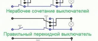
Using a changeover switch
In fact, this is also a connection to a distribution machine, only without the need to disconnect the input wiring.
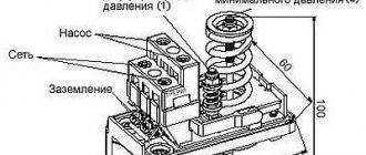
A three-position switch is mounted in front of the machine to avoid unscrewing the wiring. The task of this switch is to switch the network power from one branch to another (from an external network or generator). To perform this function, you need to select a switch with 4 input terminals (2 “phases” and 2 “zeros”), since the generator has its own “zero”, and a three-terminal switch will not work in this case. An alternative to a 3-position switch would be to install a pair of two-way machines next to each other, but rotated 180 degrees to each other. The keys of both devices are secured with pins through holes specially provided for this purpose. In operation, when switching the keys, for example, down, such a combination of machines will block the power supply to the network from the external line and open the way for the electric current generated by the autonomous generator. The opposite action with the keys will lead to the passage of current from the power line and blocking the flow of energy from the generator.
For convenience, such a switch should be installed in close proximity to the generating device, since it is launched in a certain sequence:
- Direct start of the generator engine.
- Warming up the device.
- And only then connect the load.
Naturally, it is more convenient to perform these actions and control the process in one place.
To prevent the generator from running in vain, that is, when voltage is already supplied to the backup line, it is necessary to mount a terminal for the lamp in front of the switch. Turning it on will signal the need to turn off the autonomous source and switch to supplying electricity from the main power line.
Three-phase circuits. How is voltage applied to them?
In a three-phase circuit, the voltage can be phase or linear. The vector diagram looks like this:
The graph contains three voltage (phase) vectors – Uа, Ub and Uс. The angle between them is 120°. This is observed between windings in the simplest electrical equipment. In order for the sign of the vector Ub to change to the opposite, it must be reflected in such a way that the vector beginning and end are swapped, while the original angle of inclination is preserved. After setting the vector beginning Ub to the end Ua, the resulting distance will be considered as the linear voltage vector (Ul).
How to properly connect a generator to the home network
Connecting a power plant to your home network is possible in several ways. A popular option is to connect the network reserve through a changeover switch or packet switch.
How to connect a generator to the network at home
For the case of automatic connection of a power plant with auto-start, an ATS system (automatic transfer of reserve) is used. It is also possible to connect various household appliances through an extension cord with several sockets. In this case, the extension cable cross-section is calculated based on the total load current.
Installation of a changeover switch
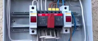
The easiest way to connect an electric generator to your home is to install a changeover switch or packet switch. The batch switch is installed on a DIN rail in the electrical panel of the house. The switch is placed near the electrical panel.
The external electrical network is connected to the upper contacts of the switch, and the lower contacts are used to connect the cable from the power plant. The middle pins connect the home network input. After installing and connecting the changeover switch, put on the protective housing.
Connecting the generator through a switch and automatic transfer switch (ATS)
It is recommended to connect the switch after the electric meter and before the water dispenser. When the mains voltage disappears, the generator is started. After the engine has warmed up, the changeover switch is moved to the lower position (to the contacts going to the generator). After the network appears, the switch is moved to the upper position and the power plant is turned off.
Connecting the power plant via ATS
For automatic control of the power grid and automatic transition to a backup generator in the event of a network failure, there is an ATS device with automatic start-up of power plants. The AVR system monitors the electrical network and, when it disappears, disconnects the magnetic starter from the network and turns on the autostart of the generator.
When the generator reaches its rated speed, another magnetic starter is turned on, which connects the home network to the power plant. When the network is restored, the ATS disconnects the home network from the generator and connects another starter to the external network.
Connecting a 3-phase generator to a three-phase network at home
This transition from the backup generator does not occur immediately after the network appears, but with some time delay until the external network becomes stable. For the case of three-phase networks, it is recommended to install a single-phase generator, and connect all necessary household appliances and equipment to it via a separate backup electrical wiring with a changeover switch.
In a private home, AVR does not always pay off, since it always has to be controlled. With the same success, you can use a changeover switch and start the power plant manually. It is recommended to use a switch in case of rare outages of the external network.
Power plant grounding
For electrical safety purposes, in cases of voltage breakdown on the generator housing, a grounding connection is required. For power plants, you can make a simple ground loop. A piece of steel pipe, a pin or a metal rod with a diameter of 20 mm and 1.5 meters in length, is driven completely into the ground.
Generator grounding
At the end of the grounding conductor it is necessary to weld a bolt for the grounding conductor. As a conductor, a copper stranded flexible wire of 4-6 mm², with external insulation, is used.
The installation location of power plants must be selected taking into account fire safety, noise, precipitation and room temperature.
Differences between linear and phase voltage
The three-phase power supply circuit for buildings and industrial facilities is popular in the Russian Federation, as it has advantages - cost-effectiveness (in terms of the use of materials) and the ability to transmit more electricity compared to a single-phase power supply circuit.
A three-phase connection makes it possible to switch on high-power generators and electric motors, as well as the ability to work with different voltage parameters, this depends on the type of load connected to the electrical circuit. To work in a three-phase network, you need to understand the relationship of its elements.
Through an automatic (distribution) switch
The ideal option is if the panel has an outlet. This method should not be confused with the one described above. On the electrical goods market, some ready-made panels are initially equipped with such outputs (it is recommended to choose them for private households). Sometimes, when assembling the panel yourself, they install an incoming AV, a meter, an RCD and one or two sockets for insurance, so it is convenient to carry out repairs. Then the generator can be connected there without any problems.
You need to be reliably aware that this is not an ordinary power outlet.
The rules must be followed:
- the socket must pass at least 16 A or more under the power of the backup device;
- AV at the input must be disabled.
If the described elements are not in the shield, then remove the input wires from the switchboard and connect the device directly to it. If RCDs and RCBOs are further installed, the polarity must be observed. Let us remind you: if you connect to the “firefighter” AB in front of the metering device, the circuit will work, but the meter will count its own electricity already produced. The introductory AB is sealed by energy sales, so more often than not the possibility of this option is completely absent. It is necessary to choose exactly the distribution (group, common) AB or RCBO after the metering device.
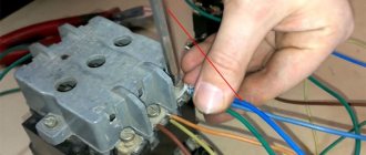
Algorithm of actions:
- Turn off the input machine. After connecting the backup source, it can be activated again, and this will be necessary before installing the control lamp.
- Unscrew the clamps on the switchgear terminals and remove the wiring.
- In place of the indicated cores, observing the polarity, especially if further than the RCD, RCBO, connect the cores from the generator cable.
- You can mount a light bulb on the folded wires, which will indicate the resumption of the main power supply; after installing it, the introductory circuit breaker is turned on.
Generators by fuel type
Since we have determined by power that a relatively small generator is needed for the house. Then cheaper and more reliable options should be considered, i.e. gasoline generators.
Diesel portable generators are not the best options for home use. They make a lot of noise. They are more difficult to start. They are initially more expensive. Small selection of manufacturers. Consumption savings are also kept to a minimum. Spare parts for them cannot be found.
The advantages of diesel engines are that portable generators do not have them (my subjective opinion).
Switch Connection
The simplest way to connect a generator is using a switch. The switch operates in three positions. In the initial position, the object is connected to a centralized power grid, without the participation of a gas generator.
When the switch moves to the next position, the object is completely de-energized. The next time you turn the switch, the power to the home network switches to a backup source - a gas generator.
Keep in mind that if the total power of all consumers is 6 kilowatts, then the switch must support at least 30 Amps.
Calculation of the relationship between phase and line voltage
To calculate the ratio, you need to know the linear parameters. All calculations are made according to the formula: 12UAB=UA cos 30˚, or UAB=2√3/2×UA=√3×UA. Thus, we conclude that the final formula looks like this – Ul=√3×UФ.
At first glance it may seem that the formulas are too complicated, but this is not so. On the other hand, there is practically no point in doing such calculations for a home master. A simple voltage check on each phase with a conventional multimeter is sufficient.
Choice
The buyer must determine from the very beginning which technical parameters are the most important for him. It is worth taking a closer look at these indicators:
- Weight.
- Dimensions.
- Power.
- Fuel consumption.
- Noise level.
- Duration of work.
Automation and price are parameters that are also being looked at
This is important for those who are interested in how to connect a generator to the home network, the diagram of which is posted on specialized websites
Generator operation
By parameters
Many people first look for an answer to the question of how many phases a generator should have for maximum convenient operation. To do this, you need to understand what electrical appliances will be connected. Three-phase options allow connection to both single- and three-phase devices. Single-phase ones are combined with only one type of consumer. But this does not mean that models with more phases will be better under all circumstances.
At each phase, the maximum load should be no more than 30%. This means that in reality the owners will not be able to use more than a third of the rated power that the outlet initially has. For example, the rated power of a three-phase generator is 6 kW. This means that no more than 2 kW can be removed from a regular 220 V outlet. The load still needs to be distributed over several phases when connecting a single-phase generator to a three-phase network at home.
Note! For power, they also check the parameters of the devices that are planned to be connected
It is important to have a reserve of at least 20-30%. Otherwise, you may encounter problems such as overload and work stoppage. Too much fuel will also be consumed
Too much fuel will also be consumed
Otherwise, you may encounter problems such as overload and work stoppage. Too much fuel will also be consumed.
Type
Synchronous and asynchronous types of devices are available. The choice involves a careful study of the characteristics of each of the existing models.
Asynchronous
Their main problem is their inability to handle so-called peak loads. Although these devices can also be used to maintain normal voltage readings. They are suitable for joint use with equipment sensitive to voltage surges:
- Electronic devices.
- Computer Engineering.
- Medical devices supporting gasoline generators.
Residual magnetization of the rotor is the main source of energy for such devices. Therefore, the service life of asynchronous generators is longer than that of their closest analogues. They do not require the use of cooling systems; the unit housing is completely closed. Thanks to this, protection from dust and moisture is fully guaranteed.
Interesting! The asynchronous generator is immune to short circuits. Therefore, this energy source is the optimal solution for welding machines. But such devices can be very sensitive to overloads. Therefore, it is prohibited to connect them to devices with initially high inrush currents.
Synchronous
The quality of the current in this case is lower when compared with the previous option. Suitable for providing emergency power in various circumstances:
- Offices.
- Refrigeration units.
- Electrical equipment in dachas and country houses.
- Construction projects.
Such devices also have some positive qualities:
- Resistance to short-term overloads.
- Ability to normally withstand peak loads, including mechanical loads.
But protection from moisture, dust and dirt is worse than that of asynchronous structures. After all, in order to cool, such generators need to pass a certain amount of air through themselves. A synchronous generator will be needed if devices operating with reactive loads are used. Then the power will be less.
Changeover switches
Phasing
It has already been mentioned above. It is worth buying three-phase generators only if there is a consumer with the appropriate characteristics in the house. If all the devices are single-phase, then the generator is selected of this type. This even applies to situations where there is a three-phase network connected to the house.
Network connection
Three-phase input and increasing power in the apartment
To increase the level of comfort in an apartment, you first need to reach the required amount of allocated power per apartment. You can understand this value by calculating the power based on the selected equipment. Almost always, an apartment is equipped with a single-phase input, but powerful modern equipment requires a three-phase input. Finally, it is necessary to obtain the missing power, put the new electrical installation of the apartment into operation and apply voltage. All these issues can be solved, but require a serious systematic approach. The first thing you need to do is contact the operating organization (MC, HOA, DEZ), get a certificate about the amount of power allocated to the apartment and find out the possibility of increasing the power. Any options are possible, but almost always the power is there, but you have to pay for it. In new houses, a reserve for sale is specially laid down during construction; in old houses, this is ensured by a safety margin from Soviet times. The cost of increasing power will be determined as a result of negotiations with the operating organization, while it must be taken into account that the consumer does not have any legal rights to receive additional power. You should not quarrel with the operating organization, as it may simply refuse you, citing disagreement with using its network or charging an exorbitantly high price. You must understand that the electrical network of your apartment is connected to the electrical network of another balance holder (MC, HOA, DEZ), which has every right to refuse you additional use of its network and not give you a new connection point to its network. Unfortunately, it is almost impossible to connect an apartment directly to the network of the electric grid company (to a transformer substation or input device), since this is extremely expensive and difficult due to the small amount of connected power. Having received the consent of the operating organization, it is necessary to conclude a purchase and sale agreement for electric power and obtain permission to connect the power to the networks of the electric grid company. A three-phase input must be specified in the power connection permit if you expect to connect three-phase equipment. According to the new laws, the cost of obtaining power under a power purchase and sale agreement is negligible for household consumers up to 15 kilowatts. Power over 15 kilowatts is paid at high tariffs for legal entities. It is advisable to agree with the operating organization so that the point of connection of the new power is as close as possible to the apartment (in the riser on the landing). This will save money when laying a new cable line. In the worst case, you will have to run a new cable line to the ASU of the building, which may be located in the basement of another entrance. If you have permission to connect and have completed work on supplying additional power, the energy sales company will enter into a new power supply contract with you without additional conditions. A power supply project is not required in this case. The only condition of the energy sales company is the availability of the required electricity meter. If you have special knowledge, it is possible to independently complete the paper part of this set of works, but in any case, for the apartment owner, the results of the negotiations will be much worse in monetary terms than for intermediary organizations. It is more profitable to entrust the entire complex of work to one authorized organization and receive a discount for the complex of work.
How to connect the generator?
The electric generator can be connected in two ways:
- Through a switch (connection to the panel);
- Using automatic or semi-automatic reserve input.
The generator is connected to the panel using a changeover or reversing switch:
- Before installing it, a cable is laid, depending on the power of the generator.
- Then the switch itself is installed in the panel in a special box, protecting it from rust and corrosion.
- After that, all that remains is to connect the switch (the main network cable is located on top, the private circuit of the house is in the center, and grounding is below), and start the generator.
Connecting a generator with a semi-automatic automatic transfer switch involves installing two semiconductors in protective boxes that are connected to each other. When the lights go out, you need to start the backup power source, then there will be an automatic transition from the main network to the generator.
Automatic reserve input means turning on the generator automatically, without any intervention.
Errors when connecting backup power
You cannot connect portable power stations if the machine in the input panel is turned off. Unfortunately, many people do this without realizing that such a step can lead to a short circuit or even a fire. Why does this happen? It's simple. The power of the reserve is many times greater than the capacity of stationary wiring. For example, for most outlets, the optimal figure is 3.5 kW. After contact with very powerful equipment, they may fail, causing the generator to fail and no longer be repairable. However, there are still effective ways to connect mini-power plants to the home network.
The installation can be connected to a home switchboard, but provided that the load power indicators are comparable to the permissible ones, and the connection is made exclusively to the switch contacts on the generator side. It makes sense to use an extension cord, and then plug in the rest of the appliances. This method will avoid short circuits through direct contact with the home network. If we are talking about arranging backup power in country houses or in the country, then experts recommend giving preference to the following connection methods:
- using a switch;
- using a reversing switch;
- using an automatic reserve start system.
Read also: What is the name of a small saw
What types of generators are there?
Many people think that generators and uninterruptible power supplies are mutually interchangeable and identical. But that's not true. UPS are devices that provide current only for a while. Their work is just enough to save important information on the computer, for example. The generator can produce electricity many times longer.
There is another device that many also confuse with generators. These are voltage stabilizers. They equalize the voltage if surges occur in the network. Stabilizers protect equipment from sudden changes in network voltage, thereby extending the service life of electrical appliances.
Before answering the question of how to connect a generator to the home network, you need to understand which generators can be connected to the home network.
There are three main types of generators based on engine type:
- gasoline;
- diesel;
- gas.
A gasoline generator is used only for a short time; its operation is not suitable for long-term loads. If the main power source is, then gasoline units should be purchased only to maintain the operation of the devices for a short time (up to 12 hours), if there are frequent network outages.
The diesel generator is the most powerful unit. This is, in fact, a diesel station that can continuously generate electricity, or be used as a backup generator for lighting the house.
Gas generators consume the least amount of fuel, which is why they are considered the most economical generators. They can operate either from a gas cylinder or from a gas main.
Also, both gas and gasoline can be used as fuel in one generator - with the ability to switch. They are called dual-fuel.
There are two more types of generators - inverter and welding. Both gas and gasoline can be used as fuel.
Inverter generators have a distinctive feature - performance adjustment. For example, during a power outage, all appliances in the house are connected to the generator. If you turn off any device, automatic performance adjustment will work, and the generator itself will reduce the load.
Welding generators are designed to power welding machines, mainly manual ones.
The number of phases and the cooling system also depend on the type of generator.
Based on the number of phases, generators are divided into single-phase (output voltage 220 V) and three-phase (380 V). The first are used in residential buildings where there is only one power and ground line. A three-phase generator provides power via three power lines, with one grounding line.
Generators use air or liquid cooling. The first is used on generators or power plants whose power does not exceed 6 kW. Liquid cooling is installed on more powerful generators, the number of engine hours of which is about thirty thousand. It is better to buy such generators on official websites or in specialized stores to prevent interference with the device by unscrupulous sellers.
How to connect a three-phase generator?
In the case of using a switch, a winding is required for each phase separately, that is, a jumper from one phase to another.
Phase and line voltage
The voltage between phase and zero is called phase. On one phase the voltage is always 220 V, and on zero, respectively, 0. Since the difference between them is 220 V, this means the phase voltage will always be 220 V (in a household network there are surges and dips, so the voltage may vary slightly).
But if everything is extremely clear with phase voltage, then with linear voltage everything is not so simple. Line voltage is the voltage between two phases. We know that it is 380V, but where does it come from?
It's all about the operation of the generator, which generates electricity and is installed at the substation. Pay attention to the illustration below. The windings (phases A, B and C) of the generator are located at an angle of 120° relative to each other. The internal inductor or magnet (indicated by the letters C and Y) rotates and creates an electromagnetic field. But since the phases are located at an angle of 120° relative to each other, the rotation of the inductor with respect to each phase is shifted by 1/3 of the cycle. As a result, when a magnet passes near one phase, it excites the winding to a maximum of 220 V, and at the same time the other phase is excited only at -160. In this case, the linear voltage will be Ul = 220 - (-160) = 380 V.
Also, for a four-wire wiring system when connecting a three-phase generator with a star, there is the following formula: Ul = square root of 3 * Uph, where Uph is the phase voltage, which is equal to 220 V. As a result, we get Ul = 1.73 * 220 = 380 V.
No matter how you decide to carry out the calculations, you will arrive at 380 V.
Automatic generator start via AVR unit
The purpose of such devices is to partially or completely eliminate human participation in the operation of the generator. There are two main types of such devices. The first completely copies the auto-switching system, which operates on two starters, but with the addition of an electronic unit for starting and stopping the generator. A low-current cable is connected to it from the main power supply line, through which the unit receives information about the presence or absence of voltage in the network. Depending on this, it sends a command to the engine to start or stop, and switching between input from the main line or from the generator is performed by the starters themselves. In general, this is the same system as the proposed scheme for self-assembly, but here you don’t have to invent anything - just install a ready-made unit.
The disadvantage of such a block is the same - its purpose is only to start and stop the engine without additional protection.
The diagram itself looks like this:
1. Introductory machine. 2. Electricity meter. 3. Automatic generator start block. 4. Generator. 5. Time relay. 6. RCD. 7. Main input contactor. 8. Backup input contactor.
A more advanced option is a complex system controlled by microprocessor electronics. In general, it works in the same way as a homemade autostart system, but its main advantage is the presence of numerous sensors that monitor all aspects of the generator's operation. If any equipment malfunction occurs, the ATS unit will be able to react adequately - not torment the generator with autostart attempts, but if there is a GSM module, send a message to the owner about the malfunction.
The ATS unit itself is mounted instead of a distribution panel - this does not require much knowledge - you just need to connect wires from the main line, power and control cables from the generator and output to the house to it.
1. Introductory machine. 2. Electricity meter. 3. AVR. 4.Generator. 5. Control cable. 6. Consumer machines. 7. Zero bus. 8. Grounding bus.
Such a unit is a complex set of equipment and its cost in some cases can be equal to the price of a generator. Therefore, its purchase is justified only in case of frequent power outages and for sufficiently powerful generators.
Voltage between two phases
In this short article, without going into the history of AC networks, we will understand the relationships between phase and line voltages. We will answer questions about what phase voltage is and what line voltage is, how they relate to each other and why these relationships are the way they are.
It's no secret that today electricity from generating power plants is supplied to consumers via high-voltage power lines with a frequency of 50 Hz. At transformer substations, high sinusoidal voltage is reduced and distributed to consumers at the level of 220 or 380 volts. Somewhere the network is single-phase, somewhere three-phase, but let's figure it out.
Effective value and amplitude value of voltage
First of all, we note that when they say 220 or 380 volts, they mean the effective voltage values, expressed in mathematical language - root mean square voltage values. What does it mean?
note
This means that in fact, the amplitude Um (maximum) of the sinusoidal voltage, phase Umph or linear Uml, is always greater than this effective value. For a sinusoidal voltage, its amplitude is greater than the effective value by the root of 2 times, that is, 1.414 times.
So for a phase voltage of 220 volts, the amplitude is equal to 310 volts, and for a linear voltage of 380 volts, the amplitude will be equal to 537 volts. And if we take into account that the voltage in the network is never stable, then these values can be either lower or higher. This circumstance should always be taken into account, for example, when choosing capacitors for a three-phase asynchronous electric motor.
Phase mains voltage
The windings of the generator are connected in a star configuration, and the ends X, Y and Z are connected at one point (at the center of the star), which is called the neutral or zero point of the generator. This is a four-wire, three-phase circuit. Linear wires L1, L2 and L3 are connected to the terminals of windings A, B and C, and neutral wire N is connected to the zero point.
The voltages between terminal A and the zero point, B and the zero point, C and the zero point are called phase voltages, they are designated Ua, Ub and Uc, but since the network is symmetrical, you can simply write Uph - phase voltage.
In three-phase AC networks in most countries, the standard phase voltage is approximately 220 volts - the voltage between the phase wire and the neutral point, which is usually grounded and its potential is taken to be zero, which is why it is also called the neutral point.
Three-phase line voltage
It will be interesting➡ All about the VVG-Png(A) cable
The voltages between terminal A and terminal B, between terminal B and terminal C, between terminal C and terminal A are called linear voltages, that is, these are the voltages between the linear conductors of a three-phase network. They are designated Uab, Ubc, Uca, or you can simply write Ul.
Standard line voltage in most countries is approximately 380 volts.
It is easy to notice in this case that 380 is 1.727 times greater than 220, and, neglecting losses, it is clear that this is the square root of 3, that is, 1.732.
Important
Of course, the voltage in the network fluctuates all the time in one direction or another depending on the current load on the network, but the relationship between linear and phase voltages is exactly that.
Where does the root of 3 come from?
In electrical engineering, the vector method of depicting voltages and currents that vary sinusoidally over time is often used. The method is based on the position that when a certain vector U rotates around the origin with a constant angular velocity ω, its projection onto the Y axis is proportional to the sine ωt, that is, the sine of the angle ω between the vector U and the X axis, which is determined at each time.
The graph of the projection magnitude versus time is a sinusoid. And if the voltage amplitude is the length of the vector U, then the projection that changes over time is the current voltage value, and the sinusoid U(ωt) reflects the voltage dynamics.
So, if we now draw a vector diagram of three-phase voltages, it turns out that between the vectors of the three phases there are identical angles of 120°, and then if the lengths of the vectors are the effective values of the phase voltages Uph, then in order to find the linear voltages Ul, it is necessary to calculate the DIFFERENCE of any pair vectors of two phase voltages. For example Ua – Ub.
Having carried out the construction using the parallelogram method, we see that the vector Ul = Ua + (-Ub), and as a result Ul = 1.732Uph. Hence it turns out that if standard phase voltages are equal to 220 volts, then the corresponding linear ones will be equal to 380 volts.
Grounding
The very principle of operation of the generator involves the periodic occurrence of static electricity on its body, therefore all permanently installed devices necessarily require a separate grounding circuit.
The ideal option is to create a full-fledged grounding loop, but in general you can get by with the simplest method, for which you will need a metal rod 1.5-2 meters long, a steel bolt or clamp connection and a soft copper wire. A bolt is welded to the iron rod, and the pin itself is driven the entire length into the ground. The copper wire is screwed with one side to the bolt (or clamped with a clamp), and the other to the generator housing - the grounding is ready.
These are all the main ways to connect a gas generator to the network at home and possible nuances. The presented diagrams will help determine whether it is worth installing autostart systems or whether it will be easier to do with manual switching. Of course, when installing each individual generator, ATS unit or homemade autostart system, additional questions may arise, but they will have to be resolved in each case separately, depending on the device model and the home electrical circuit diagram.
Scheme
Correct connection of a diesel or gasoline (gasoline generator) backup power source involves the use of additional circuits and configurations. The diagram must be drawn up correctly and efficiently, so it is better to entrust this procedure to a professional. Here all the subtleties of the home network are taken into account and permissible loads are determined. Some consumers prefer 2-3 kW installations, which are sufficient to operate for several hours after a failure. The connection diagram for a gas generator may look very simple. The main thing is that it is compiled correctly , and it ensures proper load indicators.
As mentioned above , without the proper skills or experience, there is no point in creating connection diagrams yourself. This may not lead to the most pleasant consequences, because... It is difficult for an inexperienced consumer to correctly draw up a diagram and apply it in action. Instead, it would be wise to consult with an experienced electrician and have him do the job.
Read also: Tools for grinders for cutting sheet metal
UPD: Connecting the boiler to the generator.
Often a generator is purchased to be used in winter to power the heating system boiler. There are some peculiarities here.
For imported phase-dependent boilers, it is important that the power system has a solidly grounded neutral, i.e. neutral and ground are connected together, and when connecting, the polarity is observed (phase-zero)
In the case of a portable generator, which is discussed in the article, there is neither zero nor phase. They must be made artificially - one output of the generator will be a phase (L2), and the second (N2) will be placed on the ground, i.e. ground.
In addition, as is known, boilers are very sensitive to the voltage form. And at the output of a conventional generator, the sine wave is “dirty”; if necessary, I will take an oscillogram. First of all, this happens because... The alternator that generates electricity is brushed, and because of the brushes sparking, failures, and similar unpleasant things occur.
It is because of this that Off-line and Smart UPS are not suitable for boilers. There at the output there is a quasi-sine with a bunch of harmonics, the oscillograms can be viewed here. And for boilers, Online UPS (double conversion uninterruptible power supplies) is used. For such a UPS, the shape, magnitude and frequency of the input voltage are not particularly important, because it cooks a constant voltage from all this mess, from which it then electronically receives a pure sine wave. And if the boiler is powered through such a UPS, then you can use a regular generator for its backup power.
For boilers and other sensitive equipment, it is recommended to use inverter generators - this is a generator plus an online UPS. The inverter generator includes a regular generator, which is controlled by a controller, and an inverter, which produces pure sine wave - what boilers need.
Peculiarities
To reduce the likelihood of phase overload, the load is distributed evenly across phases. Failure to comply with this condition, as well as burnout of the “zero” conductor or its poor contact, will lead to a difference in voltage on the phase conductors, up or down.
Thus, converted single-phase power (220 V) will lead to malfunction of electrical consumers connected to it. This will happen due to the fact that some devices will receive an increased voltage (240-270 V), while others will receive a reduced voltage (160-200 V).
Important! If the load is unevenly distributed across phases, on meters that are not sensitive to distortions, there will be an increased consumption of electricity.
Distribution board diagram with a “network-generator” switch
Details Published: 04 June 2015
In dacha areas, garden plots, the private sector and similar places, frequent power outages are common. Here they can turn off the lights for an hour, for the whole day or for a longer time. This creates quite a few problems, since people can no longer imagine life without electricity. He has things working at home: a refrigerator, a TV, room lighting, a pump for watering the garden, and the like.
Gasoline power plants are very popular in such places. Turn off the lights, start the gas generator and continue to enjoy life. The power plant must be connected to the distribution board through a special outlet. Below I look at the diagram of a distribution board with a “mains-generator” switch, which allows you to switch to power supply from a gas generator when the external network is lost and back.
Here I am considering manual switching, which is carried out using a reversing switch. All diagrams show an ABB OT40F3C switch. This is a high-quality and reliable reversible switch. It has three positions:
- the handle is turned to the left - the contacts on its left side are closed, and on the right side they are open;
- the handle is in a vertical position - all contacts are open (both right and left);
- the handle is turned to the right - the contacts on its right side are closed, and on the left side they are open.
If what is written is not entirely clear, then look at the latest diagram and you will immediately understand how it works.
It is worth noting that if you take such a reversing switch for a higher current, then the switch handle is not included in the kit. It must be purchased separately.
Below is a simple single-phase switchboard diagram with a mains-generator switch. This is plenty for a small dacha or garden house. If you have a large house, then you need to revise the ratings of the input machine and increase the number of group lines. Everything is individual here.
It is very convenient to use a network indicator in such panels. For example, the signal lamp LS-47. Why is she needed here? Let's say the lights are turned off and you start the power plant. Everything is working.
Next, how to determine whether there is voltage in the network or not? You won’t run to the switchboard every half hour and use an indicator to check whether the light is on or not. This is not convenient and is forgotten over time. So you can miss this moment and “sit” on the gas generator until the evening. And gasoline is expensive these days.
In such a situation, the mains voltage indicator will immediately show you when the light comes on
It will just light up and you will immediately notice it. It is clearly visible from afar even through the transparent cover of the shield. As soon as the warning light came on, they immediately turned off the power plant and switched the switch to mains mode
As soon as the warning light came on, they immediately turned off the power plant and switched the switch to mains mode.
Below is the same diagram of the distribution board, but with an LS-47 signal lamp.
If you want to protect yourself and your dacha from current leaks, then you need to install an RCD. Below is a diagram with one common protective device. If you want more, then go ahead and fight. Here you can fantasize endlessly.
For a better understanding of the operation of such a circuit, I schematically showed the state of the contacts of the reversing switch with red lines and the direction of the current with red arrows.
Below is the work from an external network.
And here the work from a gas generator is already presented.
And these are already two diagrams of the operation of this switchboard in one. It looks like a cartoon. Like?
At the request of site visitors, I am posting below a 3-phase electrical panel diagram with a “network-generator” switch
Also don't forget to smile:
A drunk man goes home and hits his head on every lamppost. Then an acquaintance meets him and asks: “Why are you hitting the pillars like that, why are they bothering you?” Can't get around? “That’s not the point at all, it’s just how I determine the way home.” - Didn't understand. - What’s incomprehensible here? Here are 3 more pillars along this street, then 7 more along another - and I’m home.
Power distribution system
Initially, the voltage is always three-phase. By “initially” I mean a generator at a power plant (thermal, gas, nuclear), from which a voltage of many thousands of volts is supplied to step-down transformers, which form several voltage stages. The last transformer lowers the voltage to a level of 0.4 kV and supplies it to end consumers - you and me, apartment buildings and the private residential sector.
Large enterprises with power consumption of more than 100 kW usually have their own 10/0.4 kV substations.
Visually:
Three-phase power supply – stages from generator to consumer
The figure shows in a simplified way how from generator G a voltage (everywhere we are talking about three-phase) 110 kV (can be 220 kV, 330 kV or another) is supplied to the first transformer substation TP1, which lowers the voltage for the first time to 10 kV. One such transformer substation is installed to power a city or region and can have a capacity of the order of a few to hundreds of megawatts (MW).
Next, the voltage is supplied to the second stage transformer TP2, at the output of which the end-user voltage is 0.4 kV (380V). The power of transformers TP2 is from hundreds to thousands of kW. From TP2, voltage is supplied to us - to several apartment buildings, to the private sector, etc.
Such voltage level conversion stages are necessary in order to reduce losses during the transportation of electricity. Read more about losses in cable lines in my other article.
The circuit is simplified, there may be several steps, the voltage and power may be different, but the essence does not change. There is only one final voltage of consumers - 380 V.
Connection diagram of a single-phase generator to a three-phase network
Let's consider the key points of connecting a single-phase generator to a three-phase network. Recently, this topic was created on the forum, and I decided to give a more detailed answer, as well as discuss this issue on the blog, since many readers do not visit the forum.
Connecting a single-phase generator is relevant for private houses and cottages that want to have an independent power source.
Many luxury houses (cottages) have three-phase input due to high power consumption. Here the question may arise: what kind of generator is needed? A three-phase generator of the required power suggests itself.
Generator for a private home
Is a three-phase generator really necessary?
I will not give a definitive answer to this answer, however, I assume that a single-phase generator will be cheaper than a three-phase one.
I have already told you why three-phase input is bad. The main problem is that it is very difficult to achieve uniform phase distribution. Perhaps the generator does not tolerate operating modes very well when there is constant phase imbalance.
But how can we convert our three-phase shield into a single-phase one?
Everything is very simple. Scheme for automatically connecting a single-phase generator to a three-phase network:
Connection diagram of a single-phase DG to a three-phase network
For this we need only 2 contactors, not counting the auxiliary elements.
In normal mode, consumers are connected to a three-phase network through the KM1 contactor. If the main power is turned off, the generator starts. Starting can be done using the additional contact of the KM1 contactor. Contactor KM1 is turned off, and contactor KM2 is turned on and combines phase 3 into one.
If you do not need automatic starting of the generator, then instead of this ATS you can use, for example, a cam switch for the appropriate power. The connection diagram is similar to KM2. Here we must use either two manual switches or 1 switch, and turn off the supply network with an input circuit breaker.
Which solution is preferable? The choice is yours.
I also advise you to review my old articles:
I recommend reading:
“Scheme for connecting a single-phase generator to a three-phase network”
“At the same time, do not forget that the power of a single-phase generator will be at least 2 times greater than a three-phase one.”
They didn’t write about the zero cross section.
I don't understand the question about power.
The cross section of the zero is not less than the cross section of the phase wire. For example, VVG-3×16.
Why will the power of a single-phase generator be at least 2 times greater than a three-phase one?
About zero. Which cable to lay from the automatic transfer switch to the distribution board with a three-phase input with a power of 15 kW. Emergency diesel is acceptable at 15 kW.
Single-phase diesel respectively.
You calculate the current, select the machine, and then select the cable cross-section. At 15kVA - VVG-3×16
But then how will there be power from the network in three-phase mode?
The supply cable from the three-phase network will be your own, for example SIP4-4×16 or SIP4-4×25.
from the support to the ATS and from the diesel engine to the ATS everything is already clear. What kind of cable is placed from the AVR to the distribution board? And why is the power of a single-phase generator 2+ times greater than the power of a three-phase generator?
After AVR, you will have group lines. There should be no intermediate shields.
When you transfer all electric motors to one phase, the total Kc should decrease, therefore the power of the single-phase generator will be Pantryk:
There should be no intermediate shields.
If the ATS is built into a panel with group devices, then yes, there will be devices right away. And if the AVR is a separate design. It includes two cables (one from the diesel engine and one from the support) and one goes to the panel with group devices. So I’m talking about the zero of such a cable. Or for example, I have a two-story mansion and the allocated power is 30 kW, and I set the diesel to the same 15 kW. At the same time, I have a switchboard for the second floor. It is three phase. It comes with a 5x4 cable. And now we apply common-mode voltage to all phases. What happens to zero? In the particular case with one input distribution board, nothing bad will happen because The tire section is quite sufficient
But in the general case of using a single-phase generator in a three-phase network, it is worth paying attention to the zero cross-section in three-phase cables and groups
I did not consider all the nuances in detail, and did not become attached to a specific object. We always need to look at what currents we will have and, depending on them, select machines and cable sections.
If you have a project, we can discuss it in more detail on the forum.
Where is the voltage used at 220V, and where at 380V?
In most residential buildings (apartments, houses, cottages and country houses), single-phase electrical networks are installed and used, in which the voltage is standard 220V. This is justified by the fact that the level of consumption in an ordinary house or apartment does not, as a rule, exceed 10 kW.
A three-phase electrical network is installed at facilities where the planned level of power consumption exceeds 10 kW, and electrical installations are installed and used that require a three-phase voltage supply to ensure correct operation. For example, if you use only one phase using a capacitor to start a three-phase motor, this will significantly reduce the efficiency of the electrical installation and at the same time increase the consumption of electrical energy.
On the other hand, if the level of maximum power consumption in a private household does not exceed 9 kW, it is permissible to use a two-core copper cable with a cross-section of 6 mm at the input and install a 40A machine.
In the case where the maximum load is supposed to be 15 kW, for a wire of one phase the value of the passing current will be 70A. Therefore, it will be necessary to install a copper wire with a 10 mm cross-section and a power circuit breaker. However, the cost of such a network is much more expensive. Therefore, a way out of the situation may be to install a conventional three-phase network and distribute the effective load equally between the phases, that is, 5 kW each. Today, such power supply solutions are used by most shops, enterprises and offices.