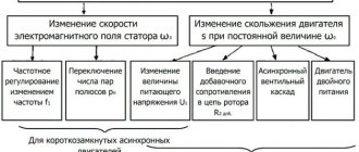
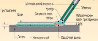
Among electrical machines designed to perform mechanical work, three-phase units are considered one of the most productive. The rotor rotates through the simultaneous influence of magnetic flux from the phase windings. Which ensures the simultaneous force of three moments at once, proportionally interacting with each other. How you can connect a three-phase motor, depending on their design features and the parameters of the electrical network, we will consider further.
Selecting a starting capacitor for an electric motor
A modern approach to this issue involves the use of special calculators on the Internet that perform quick and accurate calculations.
To carry out the calculation, you should know and enter the following indicators:
- Motor winding connection type: delta or star. The capacitance also depends on the type of connection.
- Engine power is one of the determining factors. This indicator is measured in Watts.
- Mains voltage is taken into account in calculations. As a rule, it can be 220 or 380 Volts.
- Power factor is a constant value that is often 0.9. However, it is possible to change this indicator during calculation.
- The efficiency of the electric motor also affects the calculations performed. This information, as well as others, can be found by studying the information printed by the manufacturer. If it is not there, you should enter the engine model on the Internet to search for information about what the efficiency is. You can also enter an approximate value, which is typical for such models. It is worth remembering that efficiency may vary depending on the condition of the electric motor.
Such information is entered into the appropriate fields and an automatic calculation is carried out. At the same time, we obtain the capacity of the working condensate, and the starting condensate should have an indicator 2.5 times greater.
You can carry out such a calculation yourself.
To do this, you can use the following formulas:
- For the star winding connection type, the capacitance is determined using the following formula: Cр=2800*I/U. In the case of a triangle connection of the windings, the formula Cр=4800*I/U is used. As you can see from the information above, the type of connection is the determining factor.
- The above formulas determine the need to calculate the amount of current that passes through the system. For this, the formula is used: I=P/1.73Uηcosφ. For the calculation you will need engine performance indicators.
- After calculating the current, you can find the capacitance indicator of the working capacitor.
- The starting one, as previously noted, should be 2 or 3 times higher in capacity than the working one.
When choosing, you should also consider the following nuances:
- Operating temperature range.
- Possible deviation from the calculated capacity.
- Insulation resistance.
- Loss tangent.
Usually, the above parameters are not paid much attention. However, they can be taken into account to create an ideal electric motor power system.
Overall dimensions can also be a determining factor. In this case, the following dependence can be distinguished:
- Increasing the capacitance leads to an increase in the diametrical size and outlet distance.
- The most common maximum diameter is 50 millimeters with a capacitance of 400 µF. At the same time, the height is 100 millimeters.
In addition, it is worth considering that on the market you can find models from foreign and domestic manufacturers. As a rule, foreign ones are more expensive, but also more reliable. Russian versions are also often used when creating an electric motor connection network.
general information
Connecting three-phase motors involves a relatively complex operation that requires an understanding of the processes occurring in the electrical installation. For this purpose it is necessary to consider both the constituent elements and their purpose.
Structurally, three-phase electric motors consist of:
- Stator with magnetic core;
- Rotor with shaft;
- Winding.
Depending on the type of engine, there are models with a squirrel cage or wound rotor. In some, the rotor rotates only due to the electromagnetic field induced from the stator windings, in others, the rotation of the shaft receives force from the rotor field when current flows in its windings. To turn on three-phase motors, you need to understand how the phases of the windings are connected to each other.
Asynchronous or collector: how to distinguish
In general, you can distinguish the type of engine by a plate - a nameplate - on which its data and type are written. But this is only if it has not been repaired. After all, anything can be under the casing. So if you are not sure, it is better to determine the type yourself.
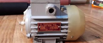
This is what a new single-phase capacitor motor looks like
How do collector motors work?
You can distinguish between asynchronous and commutator motors by their structure. The collectors must have brushes. They are located near the collector. Another mandatory attribute of this type of engine is the presence of a copper drum, divided into sections.
Such motors are produced only as single-phase ones; they are often installed in household appliances, as they allow one to obtain a large number of revolutions at the start and after acceleration. They are also convenient because they easily allow you to change the direction of rotation - you just need to change the polarity. It is also easy to organize a change in the rotation speed by changing the amplitude of the supply voltage or its cutoff angle. That is why such engines are used in most household and construction equipment.
Commutator motor structure
The disadvantages of commutator motors are high operating noise at high speeds. Remember a drill, an angle grinder, a vacuum cleaner, a washing machine, etc. The noise during their operation is decent. At low speeds, commutator motors are not so noisy (washing machine), but not all tools operate in this mode.
The second unpleasant point is that the presence of brushes and constant friction leads to the need for regular maintenance. If the current collector is not cleaned, contamination with graphite (from brushes being worn out) can cause adjacent sections in the drum to become connected and the motor simply stops working.
Asynchronous
An asynchronous motor has a stator and a rotor, and can be single or three-phase. In this article we consider connecting single-phase motors, so we will only talk about them.
Asynchronous motors are characterized by a low noise level during operation, therefore they are installed in equipment whose operating noise is critical. These are air conditioners, split systems, refrigerators.
Structure of an asynchronous motor
There are two types of single-phase asynchronous motors - bifilar (with a starting winding) and capacitor. The whole difference is that in bifilar single-phase motors the starting winding works only until the motor accelerates. Afterwards it is turned off by a special device - a centrifugal switch or a start-up relay (in refrigerators). This is necessary, since after overclocking it only reduces efficiency.
In capacitor single-phase motors, the capacitor winding runs all the time. Two windings - main and auxiliary - are shifted relative to each other by 90°. Thanks to this, you can change the direction of rotation. The capacitor on such engines is usually attached to the housing and is easy to identify by this feature.
You can more accurately determine the bifilar or capacitor motor in front of you by measuring the winding resistance. If the resistance of the auxiliary winding is twice as large (the difference can be even greater), most likely this is a bifilar motor and this auxiliary winding is a starting winding, which means that a switch or starting relay must be present in the circuit. In capacitor motors, both windings are constantly in operation and connecting a single-phase motor is possible through a regular button, toggle switch, or automatic machine.
Calculation of the total capacity
When capacitors are connected in parallel, their capacitances add up, but when they are connected in series, on the contrary, the total capacitance will be less, here the sum of the reciprocal values is equal. When two identical capacitors are connected in parallel, the total capacitance doubles, and if in series, it is halved. That is, the sum of the capacitance of two 100 microfarad capacitors can be either 200 μF or 50 μF. It all depends on the type of connection between them.
Another example: the total capacitance of capacitors of 60 μF and 90 μF with a parallel connection will be 150 μF, with a series connection - 36 μF. This can be used creatively when choosing from what you have or buying cheaper.
How to calculate the capacity of a working capacitor
For two connections of windings, slightly different ratios are taken.
The formula introduces the connection coefficient Kc, which for a triangle is 4800, and for a star - 2800.
Cр=Кс*I/U;
I=P/(√3*U*η*cosϕ);
or
Cр=Кс*P/(√3*U²*η*cosϕ).
Where the values of P (power), U (voltage 220 V), η (motor efficiency, as a percentage divided by 100) and cosϕ (power factor) are taken from the motor nameplate.
You can calculate the value using a regular calculator or using something like a similar calculation table. In it you need to substitute the values of the engine parameters (yellow fields), the result is obtained in the green fields in microfarads
Table
However, there is not always confidence that the engine operating parameters correspond to what is written on the nameplate. In this case, you need to measure the real current with a measuring clamp and use the formula Cр = Кс*I/U.
Reverse
To change the direction of rotation of the rotor, you need to switch the capacitive circuit to another wire or terminal of the electric motor box. A phase is supplied to one terminal, zero to the other, and the capacitor group is switched on to the third. Now, when the second wire of the capacitor is connected to the phase, the motor rotates in one direction, and when connected to zero, in the other.
This is enough to figure out how to connect a three-phase motor to 220, but if everything worked out and it seems to be working correctly, it turns, does not heat up, does not burn, a simple and in this case optional check will help to finally make sure that the assembled circuit is correct. While working with a constant, identical load, use a current clamp to measure the currents in the phase, neutral and capacitor wires. Ideally, they should be equal to each other; if there are small differences (30 percent), then this is not ideal, but still good.
And the difference in currents is corrected simply - by changing the capacitance of the working capacitor. It is necessary not to make sudden movements and not to burn the winding by installing too large a capacity of the working capacitor.
Model overview
electric motor AIR
One of the most popular are electric motors of the AIR series. There are models made on feet 1081, and models of combined design - feet + flange 2081.
Electric motors in the foot + flange design will cost about 5% more than similar ones with feet.
As a rule, manufacturers provide a warranty of 12 months.
For electric motors with a rotation height of 56-80 mm, the frame is made of aluminum. Motors with a rotation height of more than 90 mm are available in cast iron.
Models differ in power, rotation speed, height of the rotation axis, and efficiency.
The more powerful the engine, the higher its cost:
- An engine with a power of 0.18 kW can be purchased for 3 thousand rubles (electric motor AIRE 56 B2).
- A model with a power of 3 kW will cost about 10 thousand rubles (AIRE 90 LB2).
As for the rotation speed, the most common models are with frequencies of 1500 and 3000 rpm, although there are engines with other frequency values. With equal power, the cost of an engine with a speed of 1500 rpm is slightly higher than that of one with a speed of 3000 rpm.
The height of the rotation axis for motors with 1 phase varies from 56 mm to 90 mm and directly depends on the power: the more powerful the engine, the greater the height of the rotation axis, and therefore the price.
Different models have different efficiencies, typically ranging from 67% to 75%. Greater efficiency corresponds to a higher cost of the model.
You should also pay attention to engines produced by the Italian company AACO, founded in 1982:
- Thus, the AACO series 53 electric motor is designed specifically for use in gas burners. These motors can also be used in washing installations, warm air generators, and central heating systems.
- Electric motors of the 60, 63, 71 series are designed for use in water supply installations. Also, the company offers universal motors of the 110 and 110 compact series, which are distinguished by a diverse range of applications: burners, fans, pumps, lifting devices and other equipment.
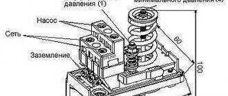
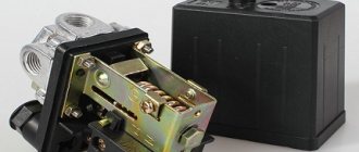
We move towards the push-button post
On the push-button post, in my case, there are two buttons - “STOP” (its contacts are constantly closed) and “START” (the contact is constantly open, and closes only when pressed). The first thing you need to do is connect the phase terminal of the working starter and the contact of the “STOP” button with a jumper, applying power to it.
We attach one end of the jumper to the phase terminal (“L1”) and stretch the contact
The second end goes to the terminal of the “STOP” button
It should also be noted that if the push-button post has already been installed somewhere, then the jumper between the “START” and “STOP” contacts may be missing. In this case, it needs to be installed. This is very easy to do - from the photo below you can clearly see how to do this kind of work.
A jumper between the start and stop button is required
We continue to connect the push-button post
Next, you need to assemble the circuit in such a way that the start button interacts with the coils of both starters. To do this, a jumper is mounted between it and one of the permanently open contacts of the working magnetic starter coil. In our case, I chose the green wire. We fix one end of it on the contact of the “START” button, to which the jumper from the stop button fits.
Connection on the start button - work with the post is almost complete
We connect the second end to the coil of the working starter and immediately tighten it too - there will be no more connections here.
Switching with permanently open contact of the working starter coil
All that remains is to complete the connection of the push-button post. We mount a jumper from the free contact of the start button to power the coil of the additional starter. Thus, it turns out that when you press the “START” button, power will be supplied to the 50 uF capacitor, but only while it is held down. If the button is released (the engine is running), the circuit is broken, the power supply to the coil is stopped, and the contacts of the additional starter open.
We connect one end of the jumper to the free contact of the “START” button. The second end of this wire is connected to the coil terminal of the additional starter
Starting a 3-phase motor from 220 Volts
Starting a 3-phase motor from 220 Volts
Often there is a need to connect a three-phase electric motor in a subsidiary farm, but there is only a single-phase network (220 V). Nothing, the matter can be fixed. You just have to connect a capacitor to the motor and it will work.
Read more in detail below
The capacity of the capacitor used depends on the power of the electric motor and is calculated by the formula
C = 66·Рnom,
where C is the capacitance of the capacitor, μF, Rnom is the rated power of the electric motor, kW.
That is, we can assume that for every 100 W of power of a three-phase electric motor, about 7 μF of electrical capacitance is required.
For example, a 600 W electric motor requires a capacitor with a capacity of 42 μF. A capacitor of such a capacity can be assembled from several parallel-connected capacitors of smaller capacity:
So, the total capacitance of the capacitors for a 600 W motor must be at least 42 μF. It must be remembered that capacitors are suitable whose operating voltage is 1.5 times the voltage in a single-phase network.
Capacitors of the KBG, MBGCh, and BGT types can be used as working capacitors. In the absence of such capacitors, electrolytic capacitors are also used. In this case, the housings of the electrolytic capacitors are connected to each other and are well insulated.
Note that the rotational speed of a three-phase electric motor operating from a single-phase network almost does not change compared to the rotational speed of the motor in three-phase mode.
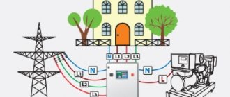
Most three-phase electric motors are connected to a single-phase network in a delta circuit (Fig. 1). The power developed by a three-phase electric motor connected in a delta circuit is 70-75% of its rated power.
A three-phase electric motor is also connected according to the “star” circuit (Fig. 2).
To make a star connection, you need to connect two phase windings of the electric motor directly to a single-phase network (220 V), and the third through a working capacitor (Cp) to any of the two network wires.
To start a three-phase electric motor of low power, usually only a running capacitor is sufficient, but with a power greater than 1.5 kW, the electric motor either does not start or picks up speed very slowly, so it is also necessary to use a starting capacitor (Cn). The capacity of the starting capacitor is 2.5-3 times greater than the capacity of the working capacitor. Electrolytic capacitors of the EP type or the same type as the working capacitors are best used as starting capacitors.
The connection diagram for a three-phase electric motor with a starting capacitor Sp is shown in Fig. 3.
Final conclusions
- Existing technical methods make it possible to connect three-phase asynchronous motors to a single-phase 220 volt network. Numerous researchers offer a wide range of experimental schemes for this purpose.
- However, this method does not ensure efficient use of electrical power resources due to large energy losses associated with poor-quality voltage conversion for connection to the stator phases. Therefore, the engine operates with low efficiency and increased costs.
- Long-term operation of machines with such engines is not economically justified.
- The method can only be recommended for connecting non-critical mechanisms for a short period of time.
- In order to effectively use an asynchronous electric motor, it is necessary to use a full three-phase connection or a modern, expensive inverter converter of appropriate power.
- A single-phase electric motor with the same power in a household network is better able to cope with all tasks, and its operation will be cheaper.
Thus, the designs of asynchronous motors, previously widely connected to home wiring, are now not popular, and the method of connecting them is outdated and rarely used.
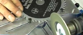
A variant of such a mechanism is shown in a photograph of an emery board with the protective shield and limit stop removed for clarity. Even with this design, it is difficult to work on it due to power losses.
Practical advice from Alexander Shenrok, presented in his video, clearly complements the material in the article and allows you to better understand this topic. I recommend viewing it, but be critical of measuring the insulation resistance with a tester.
Ask questions in the comments, share the article with friends via social network buttons.
Design and purpose of capacitors
This element of the electrical circuit consists of two plates (plates). The plates are positioned relative to each other so that there is a gap between them. When a capacitor is connected to an electric current circuit, charges accumulate on the plates. Due to the physical gap between the plates, the device has low conductivity.
Attention! This gap can be air or filled with a dielectric. The following dielectrics are used: paper, electrolyte, oxide films. The main feature of such a two-terminal network is the ability to accumulate electric field energy and instantly transfer it to the load (charge and discharge)
The main feature of such a two-terminal network is the ability to accumulate electric field energy and instantly transfer it to the load (charge and discharge).
Part device
The first prototype of the container was the Leyden jar, created in 1745 in the city of Leiden by the German von Kleist. The jar was lined with copper foil inside and out. This is how the idea of creating covers came about.
Leyden jars connected in parallel
The graphic designation of a two-terminal network on diagrams and drawings is two vertically located lines (like plates) with a gap between them.
Designation on diagrams
Download
If the topic interests you more deeply, I recommend that you read the literature listed on the page.
Here is one of the books listed there: • Lomonosov, V.Yu.; Polivanov, K.M.; Mikhailov, O.P. Electrical engineering. / Lomonosov, V.Yu.; Polivanov, K.M.; Mikhailov, O.P. Electrical engineering. One of the best books on the basics of electrical engineering. The presentation begins with the very basics: it explains what voltage, current and resistance are, provides instructions for calculating the simplest electrical circuits, and talks about the relationship and interdependence of electrical and magnetic phenomena. Explains what alternating current is and how an alternating current generator works. It describes what a capacitor is and what an inductor is, what their role is in alternating current circuits. It is explained what three-phase current is, how three-phase current generators are designed and how its transmission is organized. A separate chapter is devoted to semiconductor devices: it talks about semiconductor diodes, transistors and thyristors; on the use of semiconductor devices for rectifying alternating current and as semiconductor switches. The achievements of microelectronics are briefly described. The last third of the book is entirely devoted to electrical machines, units and equipment: chapter 10 deals with direct current machines (generators and motors); Chapter 11 is devoted to transformers; AC machines (single-phase and three-phase, synchronous and asynchronous) are described in detail in Chapter 12; switches, electromagnets and relays are described in Chapter 13; Chapter 14 deals with electrical diagramming. The last, chapter 15, is devoted to measurements in electrical engineering. This book is a great way to learn the basics of electrical engineering, to understand the fundamental principles of the operation of electrical machines and units., zip, 13.87 MB, downloaded: 2727 times./
• Starting and protection of AC motors / Starting and protection of AC motors. Starting and braking systems for AC motors. Protection devices and fault analysis of AC motors. Guide to selecting protection devices. Manual from Schneider Electric, pdf, 1.17 MB, downloaded: 2104 times./
Connecting an asynchronous motor
Three-phase alternating current
The three-phase alternating current electrical network is the most widely used among electrical energy transmission systems. The main thing in comparison with single-phase and two-phase systems is its efficiency. In a three-phase circuit, energy is transmitted through three wires, and the currents flowing in different wires are phase-shifted relative to each other by 120°, while the sinusoidal EMFs at different phases have the same frequency and amplitude.
Three-phase current (phase difference 120°)
Star and triangle
The three-phase stator winding of the electric motor is connected according to the circuit depending on the mains supply voltage. The ends of a three-phase winding can be: connected inside the electric motor (three wires come out of the motor), brought out (six wires come out), brought into a distribution box (six wires come out of the box, three wires come out of the box).
Phase voltage - potential difference between the beginning and end of one phase
Another definition for a star connection: phase voltage is the potential difference between the line wire and the neutral (note that the delta connection does not have a neutral)
Line voltage
- potential difference between two linear wires (between phases).
| Star | Triangle | Designation |
| Uл, Uф - linear and phase voltage, V, | ||
| Il, Iph - linear and phase current, A, | ||
| S — total power, W | ||
| P—active power, W |
Attention: Although the power for star and delta connections is calculated using the same formula, connecting the same electric motor in different ways to the same electrical network will result in different power consumption. In this case, incorrect connection of the electric motor can lead to melting of the stator windings.
Example: Let’s say the electric motor was connected in a star configuration to a three-phase alternating current network Ul=380 V (respectively Uph=220 V) and consumed current Il=1 A
Total power consumption:
S = 1.73∙380∙1 = 658 W.
Now let’s change the connection diagram to a “triangle”, the linear voltage will remain the same Uл=380 V, and the phase voltage will increase by the root of 3 times Uф=Uл=380 V. An increase in the phase voltage will lead to an increase in the phase current by the root of 3 times. Thus, the linear current of the delta circuit will be three times greater than the linear current of the star circuit. And therefore the power consumption will be 3 times greater:
S = 1.73∙380∙3 = 1975 W.
Thus, if the motor is designed to be connected to a three-phase AC network in a star configuration, connecting this electric motor in a delta configuration may lead to its failure.
If in normal mode the electric motor is connected in a delta circuit, then to reduce the starting currents during the start-up it can be connected in a star circuit. In this case, along with the starting current, the starting torque will also decrease.
Connecting an electric motor according to a star and delta circuit
Designation of the stator terminals of a three-phase electric motor
Designation of the terminals of the stator windings of newly developed
three-phase machines according to
GOST 26772-85
| Winding connection diagram, name of phase and output | Pin designation | |
| Start | End | |
| Open circuit (number of pins 6) | ||
| first phase | U1 | U2 |
| second phase | V1 | V2 |
| third phase | W1 | W2 |
| Star connection (number of pins 3 or 4) | ||
| first phase | U | |
| second phase | V | |
| third phase | W | |
| star point (zero point) | N | |
| Delta connection (number of pins 3) | ||
| first conclusion | U | |
| second conclusion | V | |
| third conclusion | W |
previously developed stator winding terminals
and modernized three-phase machines in accordance with
GOST 26772-85
| Winding connection diagram, name of phase and output | Pin designation | |
| Start | End | |
| Open circuit (number of pins 6) | ||
| first phase | C1 | C4 |
| second phase | C2 | C5 |
| third phase | C3 | C6 |
| Star connection (number of pins 3 or 4) | ||
| first phase | C1 | |
| second phase | C2 | |
| third phase | C3 | |
| zero point | ||
| Delta connection (number of pins 3) | ||
| first conclusion | C1 | |
| second conclusion | C2 | |
| third conclusion | C3 |
About starting three-phase motors, cosine φ and more...
I’ve seen enough videos of turners Mehamozg and Viktor Leontyev on YouTube and I wanted to fulfill my old dream - to also do metal turning. At a local bending enterprise I purchased an old and worn-out 1E61MT machine from 1969.
Inexpensive, almost at the price of scrap metal. There we were also able to purchase a drilling and sharpening machine in a similar condition. So I dragged the whole thing into the garage and the question arose of connecting all this disgrace to electricity. More precisely, this question arose even before the purchase of the machines, several solutions were come up with, and now the time has come to put the ideas into practice.
The machines, like all general industrial equipment, are designed to be connected to a three-phase 380 V network. The lathe consumes the most from this network - about 4.5 kW, most of which is consumed by the asynchronous motor of the main drive. Of course, it will consume maximum power only under the most severe cutting conditions, but still, 2-3 kW is necessary for normal operation. In the garage, there is only a single-phase 220 V network available. Although now you can use the state program and connect 3 phases 15 kW for 550 rubles, but, as people write, there may be problems of an organizational nature that could delay the resolution of the issue indefinitely. Therefore, it was decided to try to make do on our own for now.
The simplest solution today for starting an asynchronous electric motor is to use a frequency converter. In a frequency converter, the original voltage (one or three phases) is rectified to direct current (at least with mandatory correction of the power factor - cosine φ). And then, from direct current using pulse-width modulation, it is generated again, but already three phases, shifted in phase by 120 degrees.
In this case, it is possible to change the voltage and frequency of these phases within certain limits, and, accordingly, change the rotation speed of the asynchronous motor (since in asynchronous motors, the frequency of the supply network directly determines the rotor speed). Thus, you can smoothly accelerate and decelerate the engine and change its speed. This useful property of the frequency converter allows you to even slightly modernize the lathe, throw out the gearbox as unnecessary, significantly simplifying the transmission and thereby reducing the loss of mechanical energy in it, vibration and the overall noise of the machine. The frequency generator is a great thing, but the prices are still steep. Although the Chinese on Aliexpress already offer options within 10 thousand rubles. On Avito, for example, they offer from elevator control stations for 15 - 20 thousand.
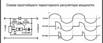
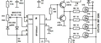
But the frequency converter does not solve all problems. Firstly, there are frequency generators for working in single-phase and three-phase networks. Typically, “single-phase” frequency converters are powered by one phase of 220 V and produce 3 phases with a phase-to-phase voltage of also 220 V (that is, for 380/220 delta-connected motors). Accordingly, “three-phase” frequency generators require 3 phases of 380 V for power supply, and also output 3 phases with a phase-to-phase voltage of 380 V. They differ in the voltage that is obtained after rectification and smoothing of the network. In “single-phase” after rectification the voltage is about 310 V, in three-phase - about 530 V. If a three-phase frequency generator is connected to only one phase, it, in principle, will work, but will complain about the low network voltage (310 instead of 530). To deceive him, some suggest changing the values of the resistors in the divider chain (in the diagram above - R1 and R2), with which the frequency controller measures the mains voltage. The divider is recalculated in such a way that when the voltage on the smoothing capacitor is 310 V, the controller thinks that there is 530 V. But this is not an option, since at the output such a frequency generator will still produce phases with an amplitude of the same 310 V, that is, it will require connecting the motor with a triangle, which is not always possible.
A better option is to supply an increased voltage of 380 V (single-phase) to the frequency generator, for example, using a step-up transformer 220/380 V. But, since in this connection option only one phase is rectified, the level of output voltage ripple will be significantly greater than when rectifying 3 phases. Therefore, it is necessary to increase the filter capacity and it is advisable to install a choke if there was none initially, fortunately, many frequency converters have additional terminals specifically for these purposes.
Another option is to remake the input rectifier and filter using a voltage doubling circuit (as is implemented in computer power supplies with a 110/220 V switch). In this case, the rectifier becomes half-wave.
According to this scheme, a voltage of 220 V is supplied to the rectifier diodes and to the midpoint of additional filter capacitors C3, C4, which in this case should have an even larger capacity than in the version with a transformer. The total voltage after such a rectifier becomes 310 + 310 = 620 V, which is already quite close to the threshold at which the frequency driver will begin to complain about excess voltage. This method is applicable for small engine powers, approximately up to 1 kW.
But I have this planned for later (either buy a frequency generator or solder it myself), but for now I decided to do it the old fashioned way. Using starting capacitors. As you know, in inductances and capacitors the phases of voltage and current do not coincide. On inductances, the current phase lags behind the voltage phase, but on capacitance, on the contrary, it leads. Thus, with the help of additional capacitance, you can shift the phase and ensure that the phases on all three terminals of the motor differ by approximately 120 degrees. These circuits have long been known, tables of the required capacitor capacities have long been calculated, they are available both on the Internet and in paper publications. The most commonly used circuit is a starting and working tank. The starting capacitance is connected briefly, only during engine acceleration. The disadvantage of this method is that the maximum engine power is reduced; it is not recommended to load it more than 70% of its maximum power.
Another problem associated with starting an asynchronous motor is that 380 motors are usually connected as a star, the phase-to-phase voltage is 380 V. To be connected to a 220 V network, the windings must be reconnected to a triangle. In this connection, the phase-to-phase voltage of the motor becomes 220 V. If the motor is connected as a 380V star to a 220V network, nothing bad will happen, nothing will burn, the motor will spin, but will not develop the required power, since the voltage on it will be 60% of the nominal. That is, in addition to the fact that the power will drop from working in a single-phase network, the power will also drop from the voltage mismatch, in the end we will get only 20-30% of the rated power. This, of course, is already too little. There is no power reserve, but there should be.
However, very often asynchronous motors are produced without the ability to manually switch the windings in the switching box. For example, all the engines that I came across were exactly like this. 3 wires simply come out of them, connected inside the engine by a star and nothing can be done about it. A long time ago I disassembled one such motor, found the connection point of the three windings inside and brought it out with three separate wires. Everything seemed to work out, the engine started working according to the triangle diagram, but this was still a lot of work. Without the necessary tools and equipment, you can ruin a lot of things. For example, bearings may be skewed, which will then begin to wear out very quickly. And also (almost always) the stator winding is filled with epoxy and, by picking at it, you can easily damage the winding itself.
I decided to do it easier. If it is impossible to reconnect the windings to 220 V, then we have no choice but to increase the voltage to the required 380 V. Turn single-phase 220 V into single-phase 380 V. This can be done using the step-up transformer mentioned above. The only thing is that such a 3-4 kW transformer will be the size of a welding transformer, weigh about the same and, on top of everything else, will cost a pretty penny. If you're lucky enough to find one at all. You can save money here by including a transformer using an autotransformer circuit.
In this case, you need a transformer with an output winding of only 160 V. For the same, for example, 2 kW of output power, the autotransformer will already have to have a power of only 840 W, which is already more or less acceptable. To build the autotransformer, I used transformers from the UPS. They can now be bought very inexpensively, since old 300-500 W UPSs are now being written off en masse, and selling such transformers for copper is not very profitable, since they have a welded magnetic circuit and cannot be disassembled without a grinder. I very successfully purchased 10 of these transformers very inexpensively at one time.
They have a voltage of about 15-16 V on the power winding. If these windings are connected in series in phase, you can get the missing 160 V. If then these 160 V are connected in series in phase with the input voltage of 220 V, we will get the 380 V we need so much.
Another good thing about this method is that you don’t have to worry about replacing starters, local lighting transformers, and other electrical fittings with similar ones, but with a voltage of 220 V. With a step-up transformer, they will work in nominal mode. In general, in a circuit you can generally use some 220 V starters and some 380 V starters, since both voltages are available.
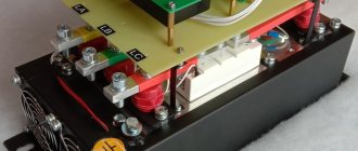
I mounted the transformers in a suitable sized iron box. The front panel displays voltmeters for input and output voltages, an ammeter for the current consumed by the load, and control lights.
The only thing is that not 10, but only 9 transformers fit into the box. I got the missing voltage by connecting 7 low-power 18 volt windings in parallel. All of them together in cross-section become equal to one force. The input of the autotransformer is protected by a double 25 A circuit breaker. One such transformer can power a lathe, drilling machine, as well as other machines that may appear in the future. A voltage of 30 and 45 V is also taken from the transformer taps, which is then rectified and is supposed to be used to brake the main drive motor with direct current. Using the toggle switch, you can select either 30 or 45 V voltage, and the rotor deceleration speed changes accordingly. From the low-power windings of two transformers connected in series, it is supposed to power 36 V LED lamps for local lighting and indication lamps. Here is a sample diagram.
From the same autotransformer it is possible in the future to power electric motors through a frequency converter.
Let's look at the engine starting circuits. For a drilling machine, the circuit is relatively simple.
When you press the “START” button, the starter is activated through one pair of contacts and self-locks, supplying voltage to two phases and through a working capacitor to the third phase. The starting capacitor is connected through another pair of contacts in parallel with the working capacitor. The button must be held down for a split second until the engine spins up. After this, the button can be released. To reverse the direction of rotation, there is a switch; the circuit remains the same, but voltage is supplied to the capacitors from a different wire and the motor begins to spin in the opposite direction. I don’t know why I need to turn the drill in the opposite direction, but since this was the operating logic of the machine initially, I kept it. When the “STOP” button is pressed, the contactor power circuit is broken and the machine is de-energized. There is also a 6 A circuit breaker at the input of the circuit.
The contactor in the diagram is drawn conventionally; in reality, for such a small machine, any very low-power starter, having only three power closing contacts and one low-power one, is sufficient.
To start the engine of a lathe, a similar scheme could be used, except that the starting capacity is required several times larger. That's what I wanted to do at first, with button control. I even purchased a convenient push-button post for this. But then I decided to leave the control from the standard drum switch of the machine. This switch type BP1-153 has three fixed positions “FORWARD”, “STOP” and “BACK”. In the “FORWARD” and “BACKWARD” positions the corresponding pair of contacts is closed. The scheme is something like this:
Each pair of contacts includes its own starter. The starter supplies power to two phases of the motor and through the working capacitance to the third phase. In this version, to change the direction of rotation, instead of changing the location of the capacitor connection, I decided to change the phasing of the power supply on two phases. As mentioned above, it is advisable to turn off the starting tank for the machine after starting it. This can be done, for example, using time relays (DA1 and DA2). After spinning up the engine, the latter becomes a 3-phase generator, from which you can power other consumers that require three-phase power, for example, a coolant pump, which is turned on by a standard package. The “FORWARD” and “BACKWARD” starters are interlocked with normally open contacts. If one is switched on, the switching circuit of the other is broken. When both starters are turned off, the circuit of the fourth starter is closed, which connects a direct current of 30 or 45 V to the two phases of the motor. This starter is turned on briefly, for a split second, to stop the spindle. Short duration is also ensured by a time relay. The circuit of a homemade time relay is shown below and is assembled on the well-known NE555 microcircuit or its analogues.
The connection circuit for the NE555 microcircuit is, in general, typical. The chain of parts R1, VD1, ... VT1, VT2 is necessary to discharge the timing capacitance after the voltage at the relay input is lost.
A few words about the starting capacity. To start the machine engine, you need a sufficiently large capacitance and a sufficiently high voltage, at least 650 V. Collecting such a capacitance from Soviet metal-paper capacitors is not a very good idea, especially if they are not at hand in sufficient quantities. Such a battery will take up a huge amount of space and cost a pretty penny. Modern capacitors are smaller in size, but can also make a big dent in the budget. By the way, you should distinguish between starting and running capacitors. Starters are designed for short-term operation and cannot withstand high reactive power for a long time. They should not be used instead of workers. A very attractive option is to use polar (electrolytic) capacitors. They have high capacity with small dimensions. They can, for example, be installed relatively free of charge on the boards of old tube monitors, televisions and any other equipment that has a switching power supply and a large “network” capacitance after the rectifier. True, their maximum voltage is usually 400 - 450 V, so to work in 380 V circuits I will have to connect 2 of them in series. For example, like this.
To operate on alternating current, such pairs are connected in back-to-back series and are shunted by protective diodes. With a positive half-wave, one capacitor works, with a negative half-wave, another. High-resistance resistors serve to discharge the battery after removing voltage from it and to equalize potentials. This scheme is suitable, for example, for a drilling machine. Here it is assembled.
A lathe requires a significantly larger capacity. When two capacitors are connected in series, the total capacitance is equal to half the capacitance of one capacitor. Therefore, in order to reach the required capacity, we will connect two such chains in parallel. If in the second chain the capacitors are turned in the opposite direction, then a ready-made diode bridge can be used as protective diodes. Approximate diagram.
A very important note for those who want to use such a circuit: this circuit is intended only for short-term operation, only as a starting capacitance. A battery of electrolytic capacitors cannot work for a long time; these capacitors also do not tolerate high reactive power, they heat up and swell.
While selecting the optimal starting and operating capacitance, I noticed an interesting feature - an electromagnetic type ammeter shows the different current consumed by the motor depending on the size of the connected capacitance. In this case, the engine operates with the same constant load. Obviously, the ammeter shows not only the active component of the consumption current, but also the reactive component too. And the reactive component, apparently, is decent. This includes the inductance of the motor, the inductance of electromagnetic starters, and the inductance of a step-up autotransformer.
To study this issue and measure the value of active and reactive power, a Chinese-made device was purchased on Aliexpress. About the same as in the photo.
The device measures and displays the voltage in the network, the current through the load, calculates active and reactive power and cosine φ. The measurement accuracy is stated to be 1% and its own power consumption <0.2 W. The device can be ordered in two versions: for a supply voltage range of 80-300 V and 200-400 V. This is exactly what you need. When I received the device, the first thing that upset me was that instead of the device I ordered for the 200-400 V range, they sent me one for 80-300. After I climbed inside the device to see how it could be converted to 380 V, a second disappointment awaited me: the device itself was powered in the simplest way using a quenching capacitor, a resistor and a zener diode. With a current consumption of 65-70 mA, this meant a power consumption of 20 W at a network voltage of 300 V. Which, of course, is unacceptable. In addition, the use of capacitive ballast introduced errors into the readings of the device itself, albeit relatively small ones. For example, when connecting a 60 W incandescent light bulb (the most active load), the device showed a cosine φ of about 0.909. I experienced the third and greatest disappointment from the product of our Chinese comrades after reading the reviews. In one of the reviews, another buyer reported that in this product the 1st and 2nd digits of the lower indicator are swapped. That is why this device showed such a large cosine φ for a purely active load. This number should actually look like 0.990. It also displayed the power incorrectly. He displayed a power of 20 W as 02 W.
In order for the device to be able to be used somehow, it had to be modified with a file. First, cut the conductors on the board, add jumpers and swap digits 1 and 2 of the lower indicator to correctly display the information. The common cathodes (or anodes) of the indicator are searched for by continuity. Secondly, I threw out all the power circuits from the quenching capacitor up to the internal 3.6 V stabilizer. Instead of the quenching circuit, I used a 5 V switching power supply from a cell phone charger that had long since become unnecessary. If you have the opportunity to choose from several such power sources, you should give preference to branded ones, which are made on a specialized PWM chip and have all the necessary noise filtering elements, rather than no-name ones made haphazardly on a single transistor. It is also necessary to replace the filter tanks on the “hot” side with higher voltage ones, at least 450 V. There are no special requirements for the power of such a power source, since the current consumed by the device does not exceed 100 mA; absolutely any charger can handle such a load. Despite the fact that there is enough free space inside the device to install some particularly small-sized power supply inside the case, I still installed it outside. Firstly, due to the fact that the 450 V filter tanks turned out to be slightly larger than what they were. And secondly, to place this source of interference away from the measuring coil, made on a ferrite ring. The modified device operates stably in the range of 80-270 V, consumes significantly less energy and does not produce an error when measuring cosine φ. When connecting a 60 W incandescent light bulb, the device readings (cosine φ) are now 0.999, that is, as they should be.
Now let’s shed some light on the question of why all this is needed. Because almost all household single-phase meters (all disk meters are 100%) count only active energy. That is, ordinary small consumers are unlikely to have to pay for reagents. Energosbyt forces only large consumers to take into account reactive energy and install total energy meters. But there are a couple of nuances that small consumers should also take into account. Large reactive power traveling through the wires, firstly, leads to heating of these same wires, and this is quite a kind of active power, which is perfectly taken into account by the meter and is then reflected in the payment receipt. If the length of these wires is large, then the losses in them can be significant. Secondly, to reserve reactive power, it is necessary to lay wires of a larger cross-section, which cost a lot of money. If they saved on the wires and laid exactly the same amount as the active power of the consumer, without a current reserve, then the additional reactive power can lead to their heating above the safe level and, also, to large losses of active energy in them. If, for example, a certain consumer consumes active power of 1 kW, but its cosine φ is only, for example, 0.33, then the total power traveling through the wires is 3 times greater! In other words, the wires for such a consumer should be designed for 3 kW. And the losses in the wires will be as much as 3 kW. Accordingly, the switching equipment must also be designed for a power of 3 kW.
In my case, the wires and switching equipment in the garage cooperative have long been laid. Moreover, in ancient times and with the expectation of a couple of Ilyich light bulbs and nothing more, and no one will change them anymore. Therefore, I would not like wires to burn out somewhere in the common panel, other unpleasant things to happen, and then to listen to all sorts of comments from the local electrician and neighbors in the garage.
Let's try to improve the cosine φ using an example with an existing small machine park. The main consumers in it are a drilling machine, a lathe and a sharpening machine. All three machines are powered through the autotransformer described above, which converts a single-phase voltage of 220 V into a single-phase 380 V. First you need to examine the situation, measure this cosine φ, evaluate how good or bad everything is. Maybe the game isn't worth the candle?
Let's connect the meter to the panel, immediately after the meter and the main machine. Thus, the device will measure network parameters at the very cable entrance to the garage. Plugging in incandescent lamps or a soldering iron into the network does not in any way worsen the cosine φ. The device displays 0.999. Turning on all LED and compact fluorescent lighting worsens the cosine φ, but only slightly, to about 0.76.
Indeed, most of them contain a pulse converter with a rectifier and a capacitive filter at the input. Light bulbs create reactivity of a capacitive nature, because connecting a radio receiver with a transformer power supply to the network improves the readings of the cosine φ.
Turning off the light bulbs and turning on the input circuit breaker of the autotransformer (unloaded), we see that the cosine φ sharply drops to a value of 0.5.
Hence the conclusion - the inductance of the transformer is subject to mandatory compensation. When the sharpening machine is turned on, the cosine φ drops to an unacceptably low level - 0.3 - which also needs to be compensated.
But when the drilling machine is turned on, the cosine φ increases slightly - this is the working capacity of the engine starting circuit, which is probably chosen to be slightly larger than required. When the lathe is turned on, the cosine φ remains at a quite acceptable level - 0.95, which means that the working capacity in it is also selected of a sufficient value.
To select a compensating capacitance, we will assemble a battery of several capacitors, each of which can be separately turned on and off with toggle switches.
We will choose capacities in the battery of 4, 6, 20, 40, 64 μF, that is, close to powers of two. Thus, by including different combinations of toggle switches, you can select any capacitance from the range of 4 -134 µF with an approximate step of 4 µF. It feels like this amount of capacitance should be enough to compensate for the existing reactivity. It is clear that it will not be possible to perfectly compensate the cosine φ to 1; for this you need to very accurately select the required capacitance, but this is not required. Let us set ourselves the goal of ensuring a cosine φ of at least 0.95 when turning on any of the existing equipment.
Selecting various combinations of capacitors, it turned out that to compensate for the inductance of the autotransformer, a capacitance of about 5 μF is needed, but I didn’t have one in my kit, so I installed 4 μF there. To compensate for the inductance of the sharpening machine, 24 uF is needed. We also selected a more optimal capacitance for the lathe - 40 uF, with this capacitance the current consumption dropped from 9 to 7 A. I also selected a capacitance for the welding transformer, although for its operating mode this is unlikely to somehow improve the situation, but at least will drive less reactant during downtime. I didn’t touch the drilling machine, everything is fine there. It is better, in my opinion, for small electrical facilities to add a compensating capacitance directly to the device that creates the reactivity. And do not make a general compensator, as is done in large industries. So that when switching on and off consumers you do not have to select a new compensating capacity. Of course, this process can be easily automated by writing a simple program for a microcontroller, if you somehow read information from the meter. But selecting and plugging in the required capacity once is much easier and more reliable (I assume that some on this site will scold me for such a simple approach, without processors and nanotechnological solutions).
By the way, if it is not possible to purchase the φ cosine meter I mentioned or a similar device, you can use any suitable electromagnetic-type panel ammeter. This device shows the total current consumption (active and reactive) and when selecting a compensating capacitance, one should be guided by the minimum readings of the device.
In general, using such simple and relatively simple methods, I was able to start three-phase motors, achieve a good power factor and, probably, some energy savings. The article does not describe anything fundamentally new or innovative, but I think the information will be useful to those who are currently solving a similar problem. Please write comments and suggestions in the comments.
Connection diagrams
Options for connecting the motor via a capacitor:
- connection diagram for a single-phase motor using a starting capacitor;
- connecting an electric motor using a capacitor in operating mode;
- connection of a single-phase electric motor with starting and running capacitors.
All these schemes are successfully used in the operation of asynchronous single-phase motors. Each case has its own advantages and disadvantages; we will consider each option in more detail.
Circuit with starting capacitor
The idea is that the capacitor is included in the circuit only at start-up; a start button is used, which opens the contacts after the rotor spins up, and by inertia it begins to rotate. The magnetic field of the main winding maintains rotation for a long time. Buttons with a group of contacts or relays are used as a short-term switch.
Since the circuit for short-term connection of a single-phase motor through a capacitor provides a button on a spring, which, when released, opens the contacts, this makes it possible to save money by making the starting winding wires thinner. To exclude an interturn short circuit, a thermal relay is used, which, when a critical temperature is reached, turns off the additional winding. In some designs, a centrifugal switch is installed, which opens the contacts when a certain rotation speed is reached.
Schemes and designs for adjusting the rotation speed and preventing overloads of the electric motor on the machine may be different. Sometimes a centrifugal switch is installed on the rotor shaft or on other elements rotating from it with a direct connection, or through a gearbox.
Under the influence of centrifugal forces, the load pulls back the springs with the contact plate, when the set rotation speed is reached, it closes the contacts, the relay switch de-energizes the engine or sends a signal to another control mechanism.
There are options when a thermal relay and a centrifugal switch are installed in the same structure. In this case, the thermal relay turns off the engine when exposed to a critical temperature or by the forces of the expanding weight of the centrifugal switch.
Due to the characteristics of an asynchronous motor, the capacitor in the additional coil circuit distorts the magnetic field lines, from round to elliptical, as a result of which power losses increase and efficiency decreases. Starting characteristics remain good.
Circuit with working capacitor
The difference between this circuit is that the capacitor does not turn off after start-up, and the secondary winding spins the rotor with pulses of its magnetic field throughout the entire operation. In this case, the power of the electric motor increases significantly; you can try to bring the shape of the electromagnetic field closer from an elliptical shape to a round one by selecting the capacitor capacitance. But in this case, the starting moment is longer and the starting currents are higher. The complexity of the circuit lies in the fact that the capacitance of the capacitor to equalize the magnetic field is selected taking into account current loads. If they change, then all the parameters will not be constant; to stabilize the shape of the magnetic field lines, you can install several capacitors with different capacities. If you turn on the appropriate capacitance when the load changes, this will improve performance, but significantly complicate the circuit and operation process.
Combined circuit with two capacitors
The best option for averaging operating characteristics is a circuit with two capacitors - starting and working.
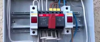
Reconnection from 380 volts to 220
It is very important to understand how a three-phase electric motor is connected to a 220V network. To connect a three-phase motor to 220V, note that it has six terminals, which corresponds to three windings. Using a tester, the wires are pinged to find the coils. We connect their ends in twos - we get a “triangle” connection (and three ends).
To begin with, we connect the two ends of the network wire (220 V) to any two ends of our “triangle”. The remaining end (the remaining pair of twisted coil wires) is connected to the end of the capacitor, and the remaining capacitor wire is also connected to one of the ends of the power wire and coils.
Whether we choose one or the other will depend on which direction the engine starts to rotate. Having completed all the above steps, we start the engine by applying 220 V to it.
The electric motor should work. If this does not happen, or it does not reach the required power, you need to return to the first stage to swap the wires, i.e. reconnect the windings.
If, when turned on, the motor hums but does not spin, you need to additionally install (via a button) a capacitor. At the moment of starting, it will give the engine a push, forcing it to spin.
Video:
Video: How to connect an electric motor from 380 to 220
Calling, i.e. resistance measurement is carried out by a tester. If this is not available, you can use a battery and a regular flashlight lamp: the identified wires are connected to the circuit in series with the lamp. If the ends of one winding are found, the lamp lights up.
It is much more difficult to determine the beginning and ends of the windings. You can't do without a voltmeter with an arrow.
You will need to connect a battery to the winding, and a voltmeter to the other.
By breaking the contact of the wire with the battery, observe whether the arrow deviates and in which direction. The same actions are carried out with the remaining windings, changing the polarity if necessary. Make sure that the arrow deviates in the same direction as during the first measurement.
How to decide on engine type
If the engine is new, then there will be no special problems, since its nameplate indicates the engine type and other data. If the engine has been repaired, then determining its type is associated with some difficulties: the plate could simply be lost or damaged mechanically. Therefore, in such cases, it is better to know how to independently determine the type of engine.
Brushed motors
Brushed motor
Determining whether a motor is commutator or asynchronous is not at all difficult, since they have different structures. A characteristic difference between a commutator motor is the presence of brushes that are stationary, as well as a commutator that rotates and consists of a set of copper plates. Brushes are pressed against these plates, transmitting electric current to the motor armature winding.
The advantage of such engines is that they accelerate quickly and allow you to get high speeds. In addition, by changing the polarity, it is possible to change the direction of rotation of the device. No less important can be considered the factor that you can easily organize control of the engine speed, with its adjustment within a wide range.
A significant disadvantage of commutator engines is their increased noise during operation, especially at high speeds. As for low speeds, the performance of these engines can be considered quite acceptable. It should also be taken into account that the friction of the brushes and commutator leads to wear of both the brushes and the commutator. As a result, you have to change the brushes or grind the commutator. If you do not constantly monitor the condition of the brushes and commutator, there is a high probability that the device will have to be repaired.
Checking the insulation resistance of the stator windings
If the engine was stored in an unheated room, it came into contact with moist air and became damp. Its insulation is broken and can create leakage currents. Therefore, its quality must be assessed by electrical measurements.
A tester in ohmmeter mode is not always able to detect such a violation. It will only show an obvious defect: the power of its current source is too low and does not provide an accurate measurement result. To check the condition of the insulation, it is necessary to use a megohmmeter - a special device with a powerful power source that ensures that an increased voltage of 500 or 1000 volts is applied to the measuring circuit.
An assessment of the insulation condition must be carried out before applying operating voltage to the windings. If leakage currents are detected, you can try to dry the engine in a warm, well-ventilated environment. Often this technique allows you to restore the functionality of the electrical circuit assembled inside the stator core.
Selecting a capacitor
In an alternating current circuit - and this is exactly our case - you should not use polar capacitors that have positive and negative contacts (anode and cathode). But if necessary, this problem can be circumvented by using a diode bridge or two polar capacitors combined into one by connecting contacts of the same name, but here again it is better to call an experienced electrician.
There is a formula for the required capacity of a working capacitor, but having calculated it, you will still need to check the operation of the device in practice. If there are any capacitors, it is better to immediately switch to the method of thoughtful selection, but thoughtful, and not completely thoughtless. Capacitors must be non-polar, have the same operating voltage, no less than 300 V, but preferably 400 V and higher.
The operating voltage of the capacitors must be the SAME, otherwise the one where it is lower will fail.
Start with a value of 30 microfarads (μF) per 1 kilowatt of rated motor power when connecting the stator windings with a star; with a triangle, you can try with 50−70 μF. The electric motor at idle speed (without load) should start and gain speed without getting too hot; prolonged idling is undesirable, the engine may burn out. If the idle start occurs normally, without overheating and a burning smell, then the working capacitor has been selected and will work on it, connect the load and continue testing in working condition.
What if the connection of a 380 V electric motor to 220 V through a capacitor occurs immediately under a serious load? Here you will need a starting capacitor; its capacitance must begin to be selected from values one and a half times greater than the working one. Example: working 60 μF, then the starting one is initially set to 90 μF and, if there is no normal starting, then we add the capacitance of the starting circuit of capacitors (the approximate capacity of the starting circuit is up to three working ones, in our example up to 180 μF). After reaching operating speed, the starting capacitors are turned off, leaving only the working one. The circuits of the working and starting capacitors are parallel; a separate switch can be placed in each.
In a household network, you do not need to use devices with a power of more than 3 kW - the protection will work or the wiring will burn out.