home
Reading time 6 min Published 06/25/2021
Each of us has some kind of electrical appliance at home that has been working in the house for more than one year. But over time, the power of the technology weakens and does not fulfill its intended purpose. This is when you should pay attention to the insides of the equipment. Mostly problems arise with the electric motor, which is responsible for the functionality of the equipment. Then you should turn your attention to a device that regulates engine speed without reducing its power.
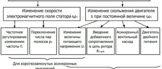
Types of engines
The speed control with power maintenance is an invention that will breathe new life into an electrical appliance, and it will work like a newly purchased product . But it is worth remembering that engines come in different formats and each has its own maximum performance.
The engines have different characteristics. This means that this or that technique operates at different speeds of the shaft that triggers the mechanism. The motor can be :
Mostly three-phase electric motors are found in factories or large factories. At home, single-phase and two-phase are used. This electricity is enough to operate household appliances.
Conclusion
When voltage is applied to asynchronous motor models, the rotor jerks. This phenomenon negatively affects the operation of both the unit itself and its drive. That is why the adjustment is carried out according to the principle of a smooth start. It is provided by the following factors:
- start via LATR;
- acceleration and operation of the motor by switching windings according to triangle/star circuits;
- the use of protective devices, for example, a frequency converter.
It is important when regulating the speed not to lose power. Using the methods described above will allow you to determine rotations without reducing productivity. A wide selection of factory models, but you can also implement the part yourself.
Power speed regulator
Work principles
A 220 V electric motor speed controller without loss of power is used to maintain the initial set shaft speed. This is one of the basic principles of this device, which is called a frequency regulator.
With its help, the electrical device operates at the set engine speed and does not reduce it . The engine speed controller also affects the cooling and ventilation of the motor. With the help of power, the speed is set, which can be either raised or reduced.
Many people have asked the question of how to reduce the speed of a 220 V electric motor. But this procedure is quite simple. One has only to change the frequency of the supply voltage, which will significantly reduce the performance of the motor shaft. You can also change the power supply to the motor by activating its coils. Electrical control is closely related to the magnetic field and motor slip. For such actions, they mainly use an autotransformer and household regulators, which reduce the speed of this mechanism. But it is also worth remembering that engine power will decrease.
Shaft rotation
Engines are divided into:
The speed controller of an asynchronous electric motor depends on the current connection to the mechanism. The essence of the operation of an asynchronous motor depends on the magnetic coils through which the frame passes. It rotates on sliding contacts. And when, when turning, it turns 180 degrees, then through these contacts the connection will flow in the opposite direction. This way the rotation will remain the same. But with this action the desired effect will not be obtained. It will come into force after a couple of dozen frames of this type are added to the mechanism.
The commutator motor is used very often . Its operation is simple, since the transmitted current passes directly - because of this, the power of the electric motor is not lost, and the mechanism consumes less electricity.
The washing machine motor also needs power adjustment. For this purpose, special boards were made that cope with their job: the engine speed control board from a washing machine has multifunctional use, since its use reduces the voltage, but does not lose rotation power.
The circuit of this board has been verified. All you have to do is install diode bridges and select an optocoupler for the LED. In this case, you still need to put a triac on the radiator. Basically, engine adjustment starts at 1000 rpm.
If you are not satisfied with the power regulator and its functionality is lacking, you can make or improve the mechanism . To do this, you need to take into account the current strength, which should not exceed 70 A, and heat transfer during use. Therefore, an ammeter can be installed to adjust the circuit. The frequency will be small and will be determined by capacitor C2.
Next, you should configure the regulator and its frequency. When outputting, this pulse will go out through a push-pull amplifier using transistors. You can also make 2 resistors that will serve as an output for the computer's cooling system. To prevent the circuit from burning out, a special blocker is required, which will serve as double the current value. So this mechanism will work for a long time and in the required volume. Power regulating devices will provide your electrical appliances with many years of service without special costs.
Read also: Control of stepper motor uln2003
Smooth engine operation, without jerks or power surges, is the key to its durability. To control these indicators, an electric motor speed controller is used for 220V, 12V and 24V; all of these frequencies can be made with your own hands or you can buy a ready-made unit.
More details:
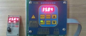
The module is a small board with all the necessary elements for wiring and built on a TDA1085c . A prerequisite for connection is the presence of a tachometer (tachogenerator), which allows for feedback from the electric motor to the microcircuit. When the engine is loaded, the speed begins to drop, which is detected by the tachometer, which commands the microcircuit to increase the voltage and vice versa, when the load weakens, the voltage to the engine drops. Thus, this design allows you to maintain constant power of the commutator motor when the rotor speed changes.
This module fits well with the electric motor from an automatic washing machine . In combination of two devices, you can easily make it yourself: Wood lathe, Milling machine, Honey extractor, Lawn mower, Potter's wheel, Wood splitter, Emery, Drilling machine, Feed cutter and other devices where rotation of mechanisms is necessary.
There is an option for capacitor power supply:
The cost of this board is 57.00 BYN .
Connection
To connect the commutator motor to the control board, you need to understand the pinout of the wires. A standard commutator motor has 3 groups of contacts: tachometer, brushes and stator winding. Rarely, there may also be a 4th group of thermal protection contacts (the wires are usually white).
Tach sensor : located at the rear of the engine with wires coming out (smaller in cross-section than the others). The wires can be probed with a multimeter and may have a slight resistance.
Brushes : wires connect with each other and the engine commutator.
Winding : wires have 2 or 3 terminals (with a middle point). The wires communicate with each other.
When connecting the commutator motor to a 220 Volt network:
We short-circuit one end of the brush and winding wires (or put a jumper in the terminal block), connect the other end of the wires to a 220V network. The direction of rotation of the motor will depend on which of the winding wires will be connected to the 220V network. If you need to change the direction of movement of the motor, place a jumper on another pair of “winding-brush” wires.
When connecting a brushed motor to the speed controller board:
We connect the wires that connected the engine to the 220V network to the “ M” . to the Taho . to the “LN” . Polarity doesn't matter.
The kit includes a switch (terminal SA ). If a switch is not needed, install a jumper.
Settings
The board provides 3 types of settings:
— adjusting the smoothness of the speed increase;
— setting the speed control range.
For operational reliability and correct setup, it is recommended to perform the setup in the following sequence:
1) Setting the smoothness of the set of revolutions is carried out by trimming resistor R1 , which is responsible for the smoothness of the set of revolutions of the commutator motor.
2) The tachometer is adjusted using trimming resistor R3, which allows you to eliminate jerking and jerking in engine operation when adjusting the rotation speed.
3) The speed adjustment range is adjusted using trimming resistor R2 . The setting allows you to limit or increase the minimum speed of the commutator motor, even with the potentiometer turned down to the minimum.
Reverse connection
To connect the reverse switch, you need to remove the jumper in the motor (winding and brushes). The wires in the switch are separated by three pairs of wires, one of which has tinned ends. The pair with tinned ends is connected to terminal M. The remaining two pairs are connected to the winding and brushes. Which pair will be connected to the winding or brushes does not matter. The polarity of the connection does not matter.
A pair of wires for connecting to the engine tach sensor is green or black.
The reverse switch is not included in the standard package of the board and must be purchased separately.
Scheme for connecting the reverse to the board:
Board is customized and tested before sale!
Specifications
Why do you need a speed controller?
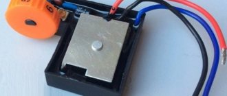
An engine speed controller, a frequency converter, is a device with a powerful transistor, which is necessary to invert the voltage, as well as to ensure smooth stopping and starting of an asynchronous motor using PWM. PWM – wide-pulse control of electrical devices. It is used to create a specific sinusoid of alternating and direct current.
Photo - a powerful regulator for an asynchronous motor
The simplest example of a converter is a conventional voltage stabilizer. But the device under discussion has a much wider range of operation and power.
Frequency converters are used in any device that is powered by electrical energy. Governors provide extremely precise electrical motor control so that engine speed can be adjusted up or down, maintaining revs at the desired level, and protecting instruments from sudden revving. In this case, the electric motor uses only the energy needed to operate, instead of running it at full power.
Photo – DC motor speed controller
Why do you need a speed controller for an asynchronous electric motor:
- To save energy. By controlling the speed of the motor, the smoothness of its start and stop, strength and speed, you can achieve significant savings in personal funds. As an example, reducing speed by 20% can result in energy savings of 50%.
- The frequency converter can be used to control process temperature, pressure or without the use of a separate controller;
- No additional controller required for soft start;
- Maintenance costs are significantly reduced.
The device is often used for a welding machine (mainly for semi-automatic machines), an electric stove, a number of household appliances (vacuum cleaner, sewing machine, radio, washing machine), home heater, various ship models, etc.
Photo – PWM speed controller
Single-phase frequency converter
The compact frequency conversion device is used to control single-phase electric motors for household equipment. Most frequency converters have the following design capabilities:
- Most models use the latest vector control technologies in their design.
- They provide improved torque for single-phase motors.
- Energy saving is set to automatic mode.
- Some models of frequency converters use a removable control panel.
- Built-in PLC controller (it is indispensable for creating data collection and transmission devices, for creating telemetry systems, and integrates devices with various protocols and communication interfaces into a common network).
- Built-in PID controller (monitors and regulates temperature, pressure and technological processes).
- The output voltage is adjusted automatically.
Fig. No. 7. Modern Optidrive converter with basic functional features.
The frequency converter does not serve for double voltage conversion; due to the presence of a PWM regulator in the design, it can increase the voltage value by no more than 10%.
The main task of a single-phase frequency converter is to provide power to both single- and three-phase electric motors. In this case, the motor current will correspond to the connection parameters from a three-phase network and remain constant
Operating principle of the speed controller
The speed controller is a device consisting of the following three main subsystems:
- AC motor;
- Main drive controller;
- Drive and additional parts.
When the AC motor is started at full power, current is transferred with the full power of the load, this is repeated 7-8 times. This current bends the motor windings and generates heat that will be generated for a long time. This can significantly reduce engine longevity. In other words, the converter is a kind of step inverter that provides double energy conversion.
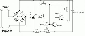
Photo - diagram of the regulator for a commutator motor
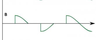
Depending on the incoming voltage, the frequency regulator of the speed of a three-phase or single-phase electric motor rectifies the current of 220 or 380 volts. This action is carried out using a rectifying diode, which is located at the energy input. Next, the current is filtered using capacitors. Next, PWM is generated, the electrical circuit is responsible for this. Now the windings of the induction motor are ready to transmit the pulse signal and integrate them into the desired sine wave. Even with a microelectric motor, these signals are issued, literally, in batches.
Read also: Pure silver how to cook
Photo – regulator diagram for brushless motors
There are two parts in this circuit - one is logical, where the microcontroller is located on the chip, and the second is power. Basically, such an electrical circuit is used for a powerful electric motor.
Video: electric motor speed controller with SHIRO V2
Carrying out regulation in AC motors
Devices operating on alternating voltage also support speed control. Let us briefly consider the main methods of such control, characteristic of AC modifications with phase-wound rotors.
Using voltage
For this purpose, autotransformers of the LATR type are used, which change the voltage on the motor windings. This is how the shaft speed is controlled.
The method is also suitable for variations with squirrel cage rotors. The operator has the opportunity to carry out control within the range from minimum to nominal engine parameters.
Regulator
Definition of resistance
The variable resistance of the rheostat (or several such phenomena) is realized directly in the rotor circuit. It affects the rotor field and current indicators, which makes it possible to change the slip values and the exact number of revolutions of the electric motor. There is a pattern: the lower the current level, the higher the motor slip rate and the lower the speed.
Advantages:
- wide range of speed control of electrical equipment;
- restrained output characteristics of the machine.
The disadvantages include:
- decrease in engine productivity;
- general decrease in the operating parameters of the mechanism.
Dual power application
Motors with dual power supplied through valve fittings are used here. The main emphasis is on changing slip performance. When regulating the operation of large specialized machines, the component supplies and regulates the amount of EMF (electromotive force) to the rotor from separately selected voltage sources.
How to make a homemade engine speed controller
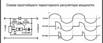
You can make a simple triac motor speed controller, its diagram is presented below, and the price consists only of parts sold in any electrical store.
To work, we need a powerful triac of the BT138-600 type, it is recommended by a radio engineering magazine.
Photo - do-it-yourself speed controller diagram
In the described circuit, the speed will be adjusted using potentiometer P1. Parameter P1 determines the phase of the incoming pulse signal, which in turn opens the triac. This scheme can be used both in field farming and at home. You can use this regulator for sewing machines, fans, tabletop drilling machines.
The principle of operation is simple: at the moment when the motor slows down a little, its inductance drops, and this increases the voltage in R2-P1 and C3, which in turn leads to a longer opening of the triac.
A thyristor feedback regulator works a little differently. It provides energy back into the energy system, which is very economical and profitable. This electronic device involves the inclusion of a powerful thyristor in the electrical circuit. His diagram looks like this:
Here, to supply direct current and rectify, a control signal generator, an amplifier, a thyristor, and a speed stabilization circuit are required.
Almost all household appliances and power tools use a commutator motor. Newer models of grinders, screwdrivers, hand routers, vacuum cleaners, mixers and others have engine speed control, but later models do not have this function. It is not always convenient to work with such tools and household appliances, and therefore there are speed controllers with power maintenance.
Design Features
The microcircuit is equipped with everything necessary for high-quality engine control in various speed modes, from braking to acceleration and rotation at maximum speed. Therefore, its use greatly simplifies the design, while simultaneously making the entire drive universal , since you can select any speed with a constant torque on the shaft and use it not only as a drive for a conveyor belt or drilling machine, but also for moving a table.
The characteristics of the microcircuit can be found on the official website. We will indicate the main features that will be required to construct the converter. These include: an integrated frequency-to-voltage conversion circuit, an acceleration generator, a soft starter, a Tacho signal processing unit, a current limiting module, etc. As you can see, the circuit is equipped with a number of protections that will ensure stable operation of the regulator in different modes.
The figure below shows a typical circuit diagram for connecting a microcircuit.
The scheme is simple, so it is quite reproducible with your own hands. There are some features that include limit values and speed control method:
- The maximum current in the motor windings should not exceed 10 A (subject to the configuration shown in the diagram). If you use a triac with a large forward current, the power can be higher. Please note that you will need to change the resistance in the feedback circuit downward, as well as the inductance of the shunt.
- The maximum rotation speed is 3200 rpm. This characteristic depends on the type of engine. The circuit can control motors up to 16 thousand rpm.
- Acceleration time to maximum speed reaches 1 second.
- Normal acceleration is achieved in 10 seconds from 800 to 1300 rpm.
- The engine uses an 8-pole tachogenerator with a maximum output voltage of 30 V at 6000 rpm. That is, it should produce 8 mV per 1 rpm. At 15,000 rpm it should show 12 V.
- To control the motor, a 15A triac with a maximum voltage of 600 V is used.
If you need to organize a motor reverse, then for this you will have to supplement the circuit with a starter that will switch the direction of the excitation winding. You will also need a zero speed control circuit to give permission for reverse. Not shown in the picture.
Types of engines and operating principles
Motors are divided into three types: commutator, asynchronous and brushless. Most power tools use the first type. This electric motor has a fairly compact size. Its power is significantly higher than that of asynchronous, and the price is quite low. As for asynchronous ones, this type is mainly used in the metalworking industry, and they are also widespread in coal mines. Quite rarely they can be found in everyday life.
The brushless electric motor is used where high speeds, precise positioning and small dimensions are needed. For example, in various medical equipment, aircraft modeling. The principle of operation is quite simple. If a rectangular frame, which has an axis of rotation, is placed between the pluses of a permanent magnet, then it will begin to rotate. The direction depends on the direction of the current in the frame. This type contains an armature and a stator. The armature rotates, but the stator stands still. As a rule, there is not one frame at anchor, but 4.5 or more.
An asynchronous motor works on a different principle. Thanks to the effect of an alternating magnetic field in the stator coils, it is driven into rotation. If you delve deeper into the course of physics, you can remember that a kind of magnetic field is created around the conductor through which the current passes, causing the rotor to rotate.
The principle of operation of the brushless type is based on turning on the windings so that the magnetic fields of the stator and rotor are orthogonal to each other, and the torque is regulated by a special driver.
The figure clearly shows that in order to move the rotor it is necessary to perform the necessary commutation, but it is not possible to regulate the speed. However, the brushless motor can rev up very quickly.
Single-phase frequency converter
The compact frequency conversion device is used to control single-phase electric motors for household equipment. Most frequency converters have the following design capabilities:
- Most models use the latest vector control technologies in their design.
- They provide improved torque for single-phase motors.
- Energy saving is set to automatic mode.
- Some models of frequency converters use a removable control panel.
- Built-in PLC controller (it is indispensable for creating data collection and transmission devices, for creating telemetry systems, and integrates devices with various protocols and communication interfaces into a common network).
- Built-in PID controller (monitors and regulates temperature, pressure and technological processes).
- The output voltage is adjusted automatically.
Fig. No. 7. Modern Optidrive converter with basic functional features.
The frequency converter does not serve for double voltage conversion; due to the presence of a PWM regulator in the design, it can increase the voltage value by no more than 10%.
The main task of a single-phase frequency converter is to provide power to both single- and three-phase electric motors. In this case, the motor current will correspond to the connection parameters from a three-phase network and remain constant
Commutator motor design
A commutator motor consists of a stator and a rotor. The rotor is the part that
rotates, but the stator is stationary. Another component of the electric motor is graphite brushes, through which current flows to the armature. Depending on the configuration, Hall sensors may be present, which make it possible to smoothly start and adjust the speed. The higher the applied voltage, the higher the speed. This type can operate on either AC or DC power.
According to the classification, commutator motors can be divided into those that operate on alternating current and direct current. They can also be divided according to the type of winding excitation: motors with parallel, series and mixed (parallel-series) excitation.
Common parameters
The operating principle and general design of such power units are known to most, because when creating or modernizing a design one cannot do without knowledge in this category. The motor consists of the following key elements:
- rotor;
- stator;
- switching unit of brush-collector type.
When power is applied to the rotor and stator, magnetic fields are formed on each of them, which interact with each other. This in turn causes rotation in the rotor.
Power is supplied to this component using graphite brushes that fit tightly to the commutator lamellas. To change the direction of rotor rotation, you need to change the position of the voltage phases on one of two elements: the stator or the rotor.
The windings of these devices can receive power from sources, or be connected to each other in parallel. It is on the basis of this feature that power units are classified into parallel and sequential. The method of exciting the copper windings depends on this.
If we talk about sequential type commutator motors, then they are most often used in household electrical appliances. This is due to the fact that it is precisely this kind of excitation that makes it possible to obtain the most overload-resistant motor.
Types of adjustment
There are quite a few options for adjusting the speed . Here are the main ones:
- Power supply with adjustable output voltage.
- Factory adjustment devices that initially come with the electric motor.
- Push-button regulators and standard regulators that simply limit the voltage.
Read also: Beautiful metal porch railings photo
These types of adjustments are bad because as the voltage decreases or increases, the power also drops. In some power tools this is acceptable, but, as practice shows, in most cases this is unacceptable due to a strong drop in power and, accordingly, efficiency.
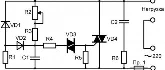
The most acceptable option would be a regulator based on a triac or thyristor. Not only does such a regulator not reduce power when the voltage decreases, it also allows for smoother starting and speed control. In addition, such a scheme can be made with your own hands. Below is a picture of the speed control with power maintenance. The circuit is assembled on the basis of a BTA 41,800 V triac .
All ratings of electrical elements are indicated in the diagram . This is the circuit after assembly, it works quite stably and provides smooth adjustment of the brushed motor. When the output voltage decreases, the power does not decrease, which is a significant plus.
If desired, you can assemble the speed controller of a 220 V brushed motor with your own hands. This circuit is assembled on the basis of a VTA26-600 triac, which must first be installed on a radiator, since this element gets quite hot under load.
It is possible to connect an electric motor with a power not exceeding 4 kW to the finished circuit.
The diagram looks like this.
It can successfully cope with the adjustment of power tools such as a drill, grinder, circular saw, and jigsaw. If desired, you can use the circuit as a power regulator for heating elements, heaters, and as a dimmer. The disadvantages include the impossibility of adjusting the power of devices powered by direct current.
Measurements
It is clear that the number of revolutions needs to be determined somehow. Tachometers are used for this. They show the rotation number at the moment. You can’t simply measure speed with a regular multimeter, except in a car.
As you can see, on electric machines you can change various parameters, adjusting them to the needs of production and household use.
DIY birthday decor
Close…
Pointed-toe cowboy bootsThe principle of operation of a homemade lock is as follows. In one half there is a permanent magnet. and in the other there is a metal plate. One of them is attached to the door. The second, with the metal plate removed, is equipped with a KEM-1 reed switch and attached to the door frame. If the door is in the closed position, the two parts of the lock are pressed, the magnet acts on the reed switch, closing its contacts. If the door opens, the magnet goes away and the reed switch contacts open.
The battery, the computer system unit, even the power supply for a laptop are all best friends. I’m already silent about such good hot water bottles as my husband and I.
Take the filler and stuff the doll. When the stuffing is completely evenly distributed, sew the product up. The handles must be sewn to the body almost near the neck.
From one pallet, sanded, impregnated and varnished, you get a garden table like a coffee table, on the left in Fig. If you have a pair in stock, you can make a wall-mounted work desk-rack out of them in literally half an hour, in the center and on the right. You can also weave chains for it yourself from soft wire, covered with a PVC tube or, better, heat-shrinkable. To fully raise the tabletop, small tools are placed on the shelf of a wall pallet.
Well, if you fill a glass bowl, vase, candy dish, punch vessel or ordinary glasses with water, scattering sea pebbles on the bottom, and let the candle-tablets float freely, you will get magical lighting for a romantic New Year. For a more interesting and unexpected effect, you can experiment with the color of the water. How are studs installed on rubber?
Handmade toys for children are beautiful, cheap and enjoyable. Every child needs original and educational toys, but it is not always possible to purchase them. Today we will show you 5 examples of fun toys that you can make yourself. They can be made from cardboard, paper or wood. In general, be inspired and make your children happy more often.
For the base of such a structure, you can use thick plywood, and for its upper part - polycarbonate. Finding solar panels online today is also not a problem.
Attention! When joining panels, do not use too much force, as you may damage the joint. This is exactly how many knives a housewife should have in her kitchen so that the cooking process is always simple and enjoyable.
This is exactly how many knives a housewife should have in her kitchen so that the cooking process is always simple and enjoyable.
To make a feeder with your own hands we will need:
Timber calculation. The boards, called staves, have biconvex sides to give the cooperage product a convexity. To make them like this, you need to take the lower part of a tree trunk and split it, similar to chopping wood. If you cut it carefully, the natural integrity of the fibers will be disrupted, which is bad for such a product. You shouldn’t start figure sawing right away - the logs need to be dried for 2 months. Moreover, dry it not under the scorching sun, but in a dark, cool room.
How to weave bracelets from laces
The fact that most New Year's costumes for preschool children are easily sewn on the basis of overalls can significantly narrow and facilitate creative search. If you learn how to sew a jumpsuit - the basis for a New Year's costume and come up with (draw from) and make decorative elements for it with your own hands, then you can make amazing and quite interesting models of New Year's outfits for children. The main thing is to think through everything in advance to the smallest detail, arm yourself with knowledge on the topic - so that the result of the work will pleasantly surprise and delight everyone.
Wardrobe design
Images
DIY birthday gift for mom photo instructions
Similar news
.
With the ever-increasing growth of automation in the domestic sector, there is a need for modern systems and devices for controlling electric motors.
Control and frequency conversion in small-power single-phase asynchronous motors, launched using capacitors, allows you to save energy and activates the energy saving mode at a new, progressive level.
DC Power Regulators
Sometimes there is a need to adjust the speed of a brushed DC motor.
If the consumer does not have a lot of power, then it is possible to connect a variable resistor in series, but then the efficiency of such a regulator will drop sharply. There are schemes with which it is possible to regulate the speed quite smoothly without reducing efficiency. Such a regulator is suitable for changing the brightness of various lamps, supply voltage not exceeding 12 V. This circuit also acts as a speed stabilizer; when the mechanical load on the shaft changes, the speed remains unchanged.
This 12V DC motor speed controller circuit is quite suitable for regulating and stabilizing the speed of motors with a current not exceeding 5 A. This circuit includes a bipolar transistor driver and a 7555 timer, which ensures stable operation and smooth regulation speed. The price of the parts is quite low, which is a definite plus. You can also assemble a 12 V electric motor speed controller with your own hands.