To perform many types of work on wood, metal or other types of materials, it is not high speeds that are required, but good traction. It would be more correct to say - moment. It is thanks to him that the planned work can be completed efficiently and with minimal power losses. For this purpose, DC (or commutator) motors are used as a drive device, in which the supply voltage is rectified by the unit itself. Then, to achieve the required performance characteristics, it is necessary to adjust the speed of the commutator motor without loss of power.
Features of speed control
It is important to know that each motor, when rotating, consumes not only active, but also reactive power. In this case, the level of reactive power will be higher, which is due to the nature of the load. In this case, the task of designing devices for regulating the rotation speed of commutator motors is to reduce the difference between active and reactive powers. Therefore, such converters will be quite complex, and it is not easy to make them yourself.
You can construct only some semblance of a regulator with your own hands, but there is no point in talking about saving power. What is power? In electrical terms, it is the current drawn multiplied by the voltage. The result will give a certain value that includes active and reactive components. To isolate only the active one, that is, to reduce losses to zero, it is necessary to change the nature of the load to active. Only semiconductor resistors have these characteristics.
Therefore, it is necessary to replace the inductance with a resistor , but this is impossible, because the motor will turn into something else and obviously will not set anything in motion. The goal of lossless regulation is to maintain torque, not power: it will still change. Only a converter can cope with such a task, which will control the speed by changing the duration of the opening pulse of thyristors or power transistors.
Main goals
The speed controller in any electrical installation is designed to adjust the number of revolutions for a certain unit of time. Typically, rotation speed is measured in revolutions per minute (RPM). When the start button is pressed, a start pulse is generated; at this moment, the speed controller adjusts the engine for a soft start, adjusting the frequency, strength and voltage of the current. Certain technical procedures involve reducing the rate of movement of the working parts of the equipment by a specific amount.
Depending on the operating conditions, the speed controller connected to the electric motor can perform a number of other tasks:
- control of the current temperature state and pressure level in the system without the need to use a feedback unit with driven equipment parts or in the case of using an asynchronous motor;
- increasing the degree of conservation of electrical energy without loss of power. By adapting the engine for a smooth start, the controller reduces efficiency losses when starting and stopping the rotor, in the process of increasing or decreasing speed and adjusting thrust. If a motor is selected to operate in short bursts (for example, an air compressor), which is also quite small, a speed controller is a necessity;
- Induction motors under high shaft load use a regulator to prevent the starting impulse from being too strong. This reduces the likelihood of false triggering of protective automation by reducing the load on current-carrying networks;
- an electric motor for operation in a three-phase network requires a regulator to stabilize the speed at a certain value. This facilitates the implementation of precise technological operations, the fineness of which directly determines the quality of the final product. Violation of the technique may occur due to surges in power supply or load on the shaft. With a preinstalled regulator, the 220 volt electric motor operates more stably;
- if the system has a standard configuration and the electric motor is powered from a 220V network, the speed controller often performs only basic functions - changing the speed from zero to the permissible limit. This also includes maintaining torque when the engine is running slowly.
The availability of certain capabilities in a particular regulator model depends on its design. The principle of operation and design features also play an important role.
Generalized controller circuit
An example of a controller that implements the principle of controlling a motor without power loss is a thyristor converter. These are proportional-integral circuits with feedback, which provide strict control of characteristics, ranging from acceleration-braking to reverse. The most effective is pulse-phase control: the repetition rate of the unlocking pulses is synchronized with the network frequency. This allows you to maintain torque without increasing losses in the reactive component. The generalized diagram can be represented in several blocks:
- power controlled rectifier;
- rectifier control unit or pulse-phase control circuit;
- tachogenerator feedback;
- current control unit in the motor windings.
Before delving into a more precise device and principle of regulation, it is necessary to decide on the type of commutator motor. The control scheme for its performance characteristics will depend on this.
Related materials
A three-phase asynchronous electric motor for converting single-phase voltage into three-phase: we get 380 Volts in the garage... I have several machines in my garage: wood and metal lathes, a milling machine and a circular machine. But…
A universal drive with a Pulse-Phase Control System... The regulator serves not only for smooth regulation of the speed of a DC motor, but also...
Single-phase DC drive... The development of the electric drive is based on the principle of operation of a servo drive with a single-circuit system...
Soldering iron heating regulator in the extension cord housing... One of the first circuits for a beginning radio amateur is often a thyristor power regulator...
Wind generator based on an asynchronous motor... The design of this wind generator is quite simple and reliable. This is the first attempt at remodeling...
Atmel U211B - motor speed controller from a washing machine for a home machine... My new Datagor article is devoted to the topic of converting an electric motor from a washing machine into...
Automatic microdrill speed controller from Alexander Savov... Yes, this is my drill and for some reason everyone gets scared when they see it. Well, I feel sorry for the money for a normal one...
Controlling a stepper motor from a PC... A driver for a stepper motor that is controlled from a personal computer. Hi all! Decided…
Two-channel analog cooling controller for video cards, PC or amplifier. LM35, LM358, NE555... I got two inexpensive ATI HD4870 video cards with custom Thermaltake DuOrb cooling...
Power regulator on field-effect transistors with PHI control + device for powering 110-volt equipment from 220 volts... Hello to all Datagorians and guests of Datagoria! I offer a circuit that is easy to manufacture and set up...
A perpetual encoder (valcoder) with stable positions from a stepper motor... A mechanical encoder is an easy-to-use thing, but it has some annoying disadvantages. IN…
Drilling machine for printed circuit boards based on disk drive mechanisms... Nowadays the equipment is quickly becoming obsolete. Everything that remains out of use must be put back into use!…
Types of commutator motors
At least two types of commutator motors are known. The first includes devices with an armature and an excitation winding on the stator. The second includes devices with an armature and permanent magnets. It is also necessary to decide for what purposes the regulator needs to be designed:
- If it is necessary to regulate with a simple movement (for example, by rotating a grinding stone or drilling), then the speed will need to be changed within the range from some minimum value, not equal to zero, to the maximum. Approximate value: from 1000 to 3000 rpm. A simplified circuit with 1 thyristor or a pair of transistors is suitable for this.
- If it is necessary to control the speed from 0 to maximum, then you will have to use full-fledged converter circuits with feedback and strict control characteristics. Usually, self-taught craftsmen or amateurs end up with commutator motors with an excitation winding and a tachogenerator. Such a motor is a unit used in any modern washing machine and often fails. Therefore, let’s consider the principle of controlling this particular engine, studying its structure in more detail.
Connection methods
Before you begin integrating the speed controller, you must read the manual. The type and mechanism of operation of the existing model is indicated there. Without this information, you can make a mistake and cause a module or engine breakdown. As a rule, the connection diagram for the speed controller does not differ much between the varieties of the latter, so the user manual will present a drawing of a typical electrical circuit.
After studying the integration diagram, you need to understand how the pinout method is used. With its help, the number of pins for full control of the existing type of electric motor is determined. Next, a comparison is made between the output contacts of the electric motor and the color codes of the regulator connectors. It is necessary to select devices so that there are no unconnected outputs. If any contact remains unused, they can be short-circuited so that the operation of the motor is not disrupted. When all the symbols match, you can start connecting and connecting to the power supply.
Motor design
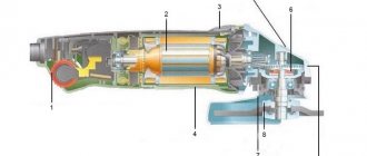
Structurally, the engine from the Indesit washing machine is simple, but when designing a controller to control its speed, it is necessary to take into account the parameters. Motors may have different characteristics, which is why the control will also change. The operating mode is also taken into account, which will determine the design of the converter. Structurally, the commutator motor consists of the following components:
- An armature, it has a winding laid in the grooves of the core.
- Collector, a mechanical rectifier of alternating mains voltage, through which it is transmitted to the winding.
- Stator with field winding. It is necessary to create a constant magnetic field in which the armature will rotate.
When the current in the motor circuit, connected according to the standard circuit, increases, the field winding is connected in series with the armature. With this inclusion, we also increase the magnetic field acting on the armature, which allows us to achieve linearity of characteristics. If the field remains unchanged, then it will be more difficult to obtain good dynamics, not to mention large power losses. It is better to use such motors at low speeds, since they are more convenient to control at small discrete movements.
By organizing separate control of the excitation and armature, it is possible to achieve high positioning accuracy of the motor shaft, but the control circuit will then become significantly more complicated. Therefore, we will take a closer look at the controller, which allows you to change the rotation speed from 0 to the maximum value, but without positioning. This may be useful if a full-fledged drilling machine with the ability to cut threads will be made from the engine from a washing machine.
Speed setting methods
To prevent negative influence during start-up, you need to reduce the speed of the electric motor 220 V or 380 V. There are several ways to achieve this goal:
- Changing the R value of the rotor circuit.
- Change in U in the stator winding.
- Change of frequency U.
- Switching poles.
When changing the R value of the rotor part using additional resistors, the rotation speed decreases, but as a result, the power decreases. Consequently, there is a significant loss of electricity. This type of regulation should be used for a wound rotor.
By changing the U values on the stator coil, mechanical or electrical control of the rotor speed is possible. In this case, the U regulator is used. Using this method allows it to be used only with a fan load (for example, a 220V fan speed regulator). For all other cases, three-phase automatic transformers are used, which allow smooth changes in U values, or thyristor regulators.
Based on the formula for the dependence of the rotation speed on the supply frequency U, it is possible to regulate the number of rotor revolutions. The frequency of the rotating magnetic field of the stator is calculated by the formula: Nst = 60 * f / p (f is the frequency of the supply network current, p is the number of pole pairs). This method provides the ability to smoothly control the rotation speed of the rotor part. To obtain a high efficiency, you need to change the frequency and U. This method is optimal for engines with a squirrel-cage rotor, since power losses are minimal. There are two methods for changing the number of pole pairs:
- In the stator (in the slots) you need to place 2 windings with different numbers p.
- The winding consists of two parts connected in parallel or in series.
The main disadvantage of this method is maintaining a stepwise change in the frequency of an electric motor with a squirrel-cage rotor.
Scheme selection
Having found out all the conditions under which the motor will be used, you can begin to manufacture a speed controller for the commutator motor. You should start by choosing a suitable scheme that will provide you with all the necessary characteristics and capabilities. You should remember them:
- Speed regulation from 0 to maximum.
- Providing good torque at low speeds.
- Smooth speed control.
Looking at many schemes on the Internet, we can conclude that few people are creating such “units”. This is due to the complexity of the control principle, since it is necessary to organize the regulation of many parameters. Thyristor opening angle, control pulse duration, acceleration-deceleration time, torque rise rate. These functions are handled by a circuit on the controller that performs complex integral calculations and transformations. Let's consider one of the schemes, which is popular among self-taught craftsmen or those who simply want to put to good use an old motor from a washing machine.
All our criteria are met by a circuit for controlling the rotation speed of a brushed motor, assembled on a specialized TDA 1085 microcircuit. This is a completely ready-made driver for controlling motors that allow you to adjust the speed from 0 to the maximum value, ensuring torque maintenance through the use of a tachogenerator.
How the device works
The operating principle and design of the engine speed controller is simple, therefore, having studied the technical aspects, it is quite possible to perform them yourself. Structurally, there are several main components that make up the rotation controllers:
- Electrical engine.
- Converter block and microcontroller control circuit.
- Mechanisms and drives.
The difference between asynchronous motors and standard drives is the rotation of the rotor with maximum power when voltage is applied to the transformer winding. At the initial stage, the current consumption and power of the motor increases to a maximum, which leads to a significant load on the drive and its rapid failure.
When the engine starts at maximum speed, a large amount of heat is released, which leads to overheating of the drive, windings and other drive elements. Thanks to the use of a frequency converter, it is possible to smoothly accelerate the engine, which prevents overheating and other problems with the unit. When using a frequency converter, the electric motor can be started at a speed of 1000 revolutions per minute, and subsequently smooth acceleration is ensured when 100-200 engine revolutions are added every 10 seconds.
Design Features
The microcircuit is equipped with everything necessary for high-quality engine control in various speed modes, from braking to acceleration and rotation at maximum speed. Therefore, its use greatly simplifies the design, while simultaneously making the entire drive universal , since you can select any speed with a constant torque on the shaft and use it not only as a drive for a conveyor belt or drilling machine, but also for moving a table.
The characteristics of the microcircuit can be found on the official website. We will indicate the main features that will be required to construct the converter. These include: an integrated frequency-to-voltage conversion circuit, an acceleration generator, a soft starter, a Tacho signal processing unit, a current limiting module, etc. As you can see, the circuit is equipped with a number of protections that will ensure stable operation of the regulator in different modes.
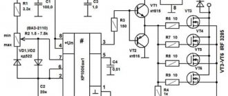
The figure below shows a typical circuit diagram for connecting a microcircuit.
The scheme is simple, so it is quite reproducible with your own hands. There are some features that include limit values and speed control method:
- The maximum current in the motor windings should not exceed 10 A (subject to the configuration shown in the diagram). If you use a triac with a large forward current, the power can be higher. Please note that you will need to change the resistance in the feedback circuit downward, as well as the inductance of the shunt.
- The maximum rotation speed is 3200 rpm. This characteristic depends on the type of engine. The circuit can control motors up to 16 thousand rpm.
- Acceleration time to maximum speed reaches 1 second.
- Normal acceleration is achieved in 10 seconds from 800 to 1300 rpm.
- The engine uses an 8-pole tachogenerator with a maximum output voltage of 30 V at 6000 rpm. That is, it should produce 8 mV per 1 rpm. At 15,000 rpm it should show 12 V.
- To control the motor, a 15A triac with a maximum voltage of 600 V is used.
If you need to organize a motor reverse, then for this you will have to supplement the circuit with a starter that will switch the direction of the excitation winding. You will also need a zero speed control circuit to give permission for reverse. Not shown in the picture.
Frequency controller structure
Currently, two main topologies of multilevel frequency converters have been developed in detail and are widely used. These are cascade and converters based on multi-level frequency voltage inverters.
Rice. No. 3 Block diagram of a high-voltage multilevel frequency converter, built on the basis of air- or water-cooled IGBT transistors.
The device includes a multi-winding transformer. Features of the circuit include the presence of power cells with a serial connection, due to which a total high voltage is obtained at the output of the device. Such a circuit serves to obtain an output voltage shape that is almost close to an ideal sine wave. The presence of cells that are shunted at the time of malfunction determines the high reliability of the circuit.
As a continuation of the previous circuit, we will consider a converter circuit based on a transformer multilevel voltage inverter with pulse width modulation using IGBT modules. The device is characterized by a fixed PWM frequency of 3 kHz. The structure of the device includes a protection system using a microprocessor.
Rice. 4 Block diagram of the converter.
The diagram shows that all blocks are functionally interconnected. The diagram shows how a frequency regulator works for an asynchronous motor, its structure and principle of operation.
The first block contains an input transformer; the block transmits electricity from a three-phase high-voltage power source. From the multi-level transformer, the reduced voltage is distributed into the inverter cabinet to the multi-level inverter.
The inverter cabinet includes a multi-level three-phase inverter consisting of converter cells. Each contains a six-pulse filter for rectifying the DC link and a bridge voltage inverter based on IGBT transistors. According to the circuit, the input alternating current is rectified, which, thanks to the inverter, is changed into alternating current with adjustable frequency and voltage.
The control protection cabinet contains a microprocessor unit with multifunctional capabilities and a power supply system from the converter TSN, a converter input device and primary sensors indicating the operating modes of the converter.
The microprocessor is used to generate inverter control signals depending on the designated operating algorithm. It is used to process information collected from voltage and current sensors. The microprocessor generates signals to control protections and emergency control buttons, and adjusts the control algorithm.
Fiber optic cable is used to transmit information and communication. For uninterrupted operation there is an independent built-in power supply. Parameter editing is performed using the remote control.
For reliable shutdown and safe performance of various types of work, the converter is equipped with a linear disconnector.
Rice. No. 5 Generalized diagram of the converter cell
Controlled alternating voltage sources form a voltage phase to perform their series connection. The output circuit of the supply network of an asynchronous motor occurs according to the “Star” winding connection diagram. The voltage in a three-phase inverter is distributed according to the circuit.
Rice. No. 6 Voltage distribution diagram in the inverter into three phases.
Control principle
When the rotation speed of the motor shaft is set by a resistor in output circuit 5, a sequence of pulses is formed at the output to unlock the triac by a certain angle. The speed of rotation is monitored by a tachogenerator, which occurs in digital format. The driver converts the received pulses into an analog voltage, which is why the shaft speed is stabilized at a single value, regardless of the load. If the voltage from the tachogenerator changes, the internal regulator will increase the level of the output control signal of the triac, which will lead to an increase in speed.
The microcircuit can control two linear accelerations, allowing you to achieve the dynamics required from the engine. One of them is installed on the Ramp 6 output circuit . This regulator is used by washing machine manufacturers themselves, so it has all the advantages to be used for domestic purposes. This is ensured by the presence of the following blocks:
- Voltage stabilizer to ensure normal operation of the control circuit. It is implemented at pins 9, 10.
- Rotation speed control circuit. Implemented using MS pins 4, 11, 12. If necessary, the controller can be switched to an analog sensor, then pins 8 and 12 are combined.
- Starting impulse block. It is implemented at pins 1, 2, 13, 14, 15. It adjusts the duration of control pulses, delays, generates them from a constant voltage and calibrates.
- Sawtooth voltage generation device. Pins 5, 6 and 7. It is used to control the speed according to the set value.
- Control amplifier circuit. Pin 16. Allows you to adjust the difference between the set and actual speed.
- Current limiting device at pin 3. When the voltage on it increases, the triggering angle of the triac decreases.
The use of such a circuit ensures full control of the commutator motor in any mode. Thanks to forced acceleration control, it is possible to achieve the required acceleration speed to a given rotation speed. Such a regulator can be used for all modern washing machine motors used for other purposes.
Making homemade relays
Making a homemade speed controller for a 12 V electric motor will not be difficult. For this work you will need the following:
- Wirewound resistors.
- Switch for several positions.
- Control unit and relay.
The use of wirewound resistors allows you to change the supply voltage and, accordingly, the engine speed. Such a regulator provides stepwise acceleration of the engine, has a simple design and can be made even by novice radio amateurs. Such simple homemade step regulators can be used with asynchronous and contact motors.
Operating principle of a homemade converter:
- Power from the network is sent to the capacitor.
- The used capacitor is fully charged.
- The load is transferred to the resistor and the bottom cable.
- The thyristor electrode connected to the positive terminal on the capacitor receives the load.
- A voltage charge is transmitted.
- The discovery of the second semiconductor occurs.
- The thyristor passes the load received from the capacitor.
- The capacitor is completely discharged, after which the half-cycle is repeated.
In the past, the most popular were mechanical regulators based on a variator or gear drive. However, they were not very reliable and often failed.
Homemade electronic regulators have proven themselves to be the best. They use the principle of changing step or smooth voltage, are durable, reliable, have compact dimensions and provide the ability to fine-tune the operation of the drive.
The additional use of triacs and similar devices in electronic regulator circuits allows for a smooth change in voltage power; accordingly, the electric motor will correctly gain speed, gradually reaching its maximum power.
To ensure high-quality regulation, variable resistors are included in the circuit, which change the amplitude of the incoming signal, providing a smooth or step change in the speed.
Screwdriver force regulator
The force regulator is a clutch that limits the force when the chuck rotates. It is made in the form of a rotating plastic drum. The amount of tightening is adjusted using a digital scale located around the circumference of the drum. By increasing the tightening value, you screw the screw in deeper.
This function will be necessary when working with material products of varying degrees of hardness, since when working with soft material, the body of the self-tapping screw will be easily recessed into it; too high a hardness of the material will contribute to the violation of the geometry of the screw, especially if it is small in size. The ratchet, as the regulator is also called, prevents cutting off the splines of the screws, as well as wear on the screwdriver attachments. The adjusting ring should be tightened in stages, starting with the slightest force. In those screwdrivers in which drilling can be done, the last pictogram on the ring will be in the form of a drill. In this position, maximum torque is achieved.
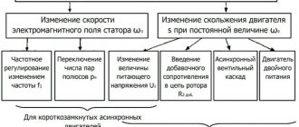
Changing the speed of an IM with a squirrel-cage rotor
There are several ways:
- Rotation control by changing the electromagnetic field of the stator: frequency regulation and changing the number of pole pairs.
- Changing the slip of the electric motor by decreasing or increasing the voltage (can be used for IMs with a wound rotor).
Frequency regulation
In this case, the adjustment is made using a frequency conversion device connected to the engine. For this purpose, powerful thyristor converters are used. The process of frequency regulation can be considered using the example of the EMF formula of a transformer:
This expression means that in order to maintain a constant magnetic flux, which means maintaining the overload capacity of the electric motor, the supply voltage level should be adjusted simultaneously with frequency conversion. If the expression calculated by the formula is saved:
then this means that the critical moment has not been changed. And the mechanical characteristics correspond to the figure below; if you do not understand what these characteristics mean, then in this case the adjustment occurs without loss of power and torque.