Scope of application of circuit breakers and switches
From all of the above, it is clear that such devices are designed to switch circuits that under no circumstances should be connected to each other.
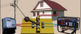
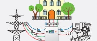
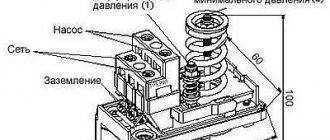
One striking example is switching an object to a backup source. Suppose you are tired of constant power outages in your country house and have acquired a gas generator. The electricians turned off the power, you switched to the generator. Turned it on - you are powering your house again from the standard network. Everything is simple in words, but how to do it practically? This is where a changeover switch will help you out. Take a look at the diagram below: In one switch position the house is connected to the mains, in the other it is connected to the generator. Moreover, even if there is voltage in both the network and the generator, switching does not threaten anything - it is impossible to connect the network to the generator. Unfortunately, although this scheme is simple, it is not entirely correct. Let's look at the actions you must take when connecting the generator:
- Disconnect the house from the standard electrical network.
- Start the generator and bring it into operating mode.
- Connect the house to the generator.
You don’t need to be a rocket scientist to understand that it is impossible to perform such a sequence of operations with a conventional changeover device. You will either have to start the generator first and then switch, or switch sources and then start the generator.
If the first option is still suitable, then the second is absolutely unacceptable for most household appliances. How will a refrigerator feel, for example, if during the startup of a gas generator the supply voltage begins to rise from 0 to 220 V, and the frequency from 0 to 50 Hz? If you don't know, it will burn.
Regular switch and pass-through
As can be seen from the figure, the pass-through switch transfers the working contact to one of the output contacts. To make it easier to see, we painted the veins in different colors. In this case, it is clearly visible that at a certain position the neutral and phase are short-circuited. And this is a fire, broken traffic jams, a lot of nerves and worries. Remember a simple rule: a pass-through switch is never placed in the same circuit as a regular one. So that something doesn't work out. There is, however, one working scheme using a changeover switch, which we will consider a little later (you can see the second option in advance in figure number 2).
Figure 2. Operating diagram using a changeover switch
When deciding on three lighting control points in the corridor. It throws the wiring crosswise, due to which interesting possibilities are created for organizing an infinite number of switches
Please note that despite all this manipulation of the neutral and phase, there is no possibility of creating a short circuit. That is, the pass-through switch can be used in conjunction with a conventional
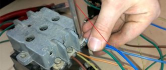
Here's what it might look like in real life:
- The light is turned off, as can be seen from the picture. Because a regular switch broke one of the wires.
- Leaving the bedroom to the kitchen, we turn on the illumination, closing the contact.
- Then we calmly go to the refrigerator (or horizontal bar - whatever).
- Having reached the threshold of the kitchen, we throw the pass-through switch, which simply changes the polarity of the phase and neutral on the light bulb.
Now there are many people who will say that it won’t work like that, but we will answer that if the power was from direct current, and this is often found on ships, cars and trains, then everything would be in order. You just need to put the diode in the right place. As for an ordinary apartment, this combination really doesn’t look the best.
Distribution board diagram with a “network-generator” switch
Details Published: 04 June 2015
In dacha areas, garden plots, the private sector and similar places, frequent power outages are common. Here they can turn off the lights for an hour, for the whole day or for a longer time. This creates quite a few problems, since people can no longer imagine life without electricity. He has things working at home: a refrigerator, a TV, room lighting, a pump for watering the garden, and the like.
Gasoline power plants are very popular in such places. Turn off the lights, start the gas generator and continue to enjoy life. The power plant must be connected to the distribution board through a special outlet. Below I look at the diagram of a distribution board with a “mains-generator” switch, which allows you to switch to power supply from a gas generator when the external network is lost and back.
Here I am considering manual switching, which is carried out using a reversing switch. All diagrams show an ABB OT40F3C switch. This is a high-quality and reliable reversible switch. It has three positions:
- the handle is turned to the left - the contacts on its left side are closed, and on the right side they are open;
- the handle is in a vertical position - all contacts are open (both right and left);
- the handle is turned to the right - the contacts on its right side are closed, and on the left side they are open.
If what is written is not entirely clear, then look at the latest diagram and you will immediately understand how it works.
It is worth noting that if you take such a reversing switch for a higher current, then the switch handle is not included in the kit. It must be purchased separately.
Below is a simple single-phase switchboard diagram with a mains-generator switch. This is plenty for a small dacha or garden house. If you have a large house, then you need to revise the ratings of the input machine and increase the number of group lines. Everything is individual here.
It is very convenient to use a network indicator in such panels. For example, the signal lamp LS-47. Why is she needed here? Let's say the lights are turned off and you start the power plant. Everything is working.
Next, how to determine whether there is voltage in the network or not? You won’t run to the switchboard every half hour and use an indicator to check whether the light is on or not. This is not convenient and is forgotten over time. So you can miss this moment and “sit” on the gas generator until the evening. And gasoline is expensive these days.
In such a situation, the mains voltage indicator will immediately show you when the light comes on
It will just light up and you will immediately notice it. It is clearly visible from afar even through the transparent cover of the shield
As soon as the warning light came on, they immediately turned off the power plant and switched the switch to mains mode.
Below is the same diagram of the distribution board, but with an LS-47 signal lamp.
If you want to protect yourself and your dacha from current leaks, then you need to install an RCD. Below is a diagram with one common protective device. If you want more, then go ahead and fight. Here you can fantasize endlessly.
For a better understanding of the operation of such a circuit, I schematically showed the state of the contacts of the reversing switch with red lines and the direction of the current with red arrows.
Below is the work from an external network.
And here the work from a gas generator is already presented.
And these are already two diagrams of the operation of this switchboard in one. It looks like a cartoon. Like?
At the request of site visitors, I am posting below a 3-phase electrical panel diagram with a “network-generator” switch
Also don't forget to smile:
A drunk man goes home and hits his head on every lamppost. Then an acquaintance meets him and asks: “Why are you hitting the pillars like that, why are they bothering you?” Can't get around? “That’s not the point at all, it’s just how I determine the way home.” - Didn't understand. - What’s incomprehensible here? Here are 3 more pillars along this street, then 7 more along another - and I’m home.
Semi-automatic switching to another source
This method involves the automation of certain (not all) switching processes. Human participation in this type of switching is still necessary, but the switching itself becomes much easier and safer for both people and equipment.
Automatic switchover
This unit, which is easy to assemble with your own hands, is designed to automatically switch the load from the main to the backup source when the first one fails and vice versa. To implement it, you will need an electromagnetic starter or relay that operates from 220 V and with contacts that can withstand the current of household consumers. As an example, we took the electromagnetic relay REK77/3 with three groups of switching contacts:
Electromagnetic relay REK77/3 with winding 220 V / 50 Hz
The device can withstand current up to 10 A, and can be used as an automatic switch in a small facility or in a private home. The circuit diagram of the machine will look like this:
Here the relay plays the role of an automatic changeover switch. One group of contacts switches phase, the other switches zero, and the third is not used. The relay coil is powered from the main network. In the initial position, there is voltage in the “Network” line, the relay is turned on and supplies voltage to the load. When the network fails, the relay releases and switches the load to power from the generator. When the power supply is restored, relay K1 is activated again, and the circuit returns to power from the main source.
This is a complete automatic transfer switch, but only in the case when the backup source itself is always energized. If a gas generator is used as a reserve, and this is most often the case, then it is clear that the system will be semi-automatic - the generator will have to be started manually.
With the start of the gas generator
This design is able to independently start the generator. The only condition is that the generator itself must have a starter and a remote start system with at least a button. To implement this idea, you will need another relay and a start timer of any design:
Connecting a gas generator to the home network, circuit with auto start
Here relay K1 performs the same functions - it switches the load when the main voltage disappears. But in addition, with its third group of contacts, it supplies voltage to the starter and time relay. The relay periodically tries to start the generator, and when it starts, voltage appears on the backup line. In this case, relay K2 is activated and its contacts disable the autostart system of the gas generator.
But this design is not fully automatic. Firstly, if the generator does not start for some reason (cold, poor start adjustment, no fuel, etc.), the device will try to start it until the starter burns out or the starting battery dies. Secondly, when the main voltage appears, the automation will switch the load to it, but will not turn off the generator.
Connection features
The choice of connection diagram for a changeover switch is influenced by the type of electrical network.
Single-phase network
You can connect such a device to this network only if it has two poles. In addition, you need to take into account that the operation of the switch is only possible if there is a power supply with suitable technical characteristics. As for jumpers that provide contact between two-pole devices, it is advisable to give preference to copper ones.
Two-phase network
How to connect a switch with your own hands if the network is two-phase? The circuit involves the use of a 200V power supply. Also, for these devices you need to use only expansion switches. Only then can the devices be used in a three-phase power supply network, regardless of the number of modules used.
The maximum voltage for such devices will be 300V, and the maximum negative resistance will be 40 Ohms. The contacts in such devices are applicable exclusively to closed models, and fluctuations in electrical energy are controlled using pass-type capacitors.
Three-phase network
For this type of electrical network, reversible switches are used. They provide a complete uninterrupted supply of electric current, distributing the load over several lines and completely preserving the power supply. Here you need to use 400 V power supplies. It would also be appropriate to use pulse transformers.
Choice
The buyer must determine from the very beginning which technical parameters are the most important for him. It is worth taking a closer look at these indicators:
- Weight.
- Dimensions.
- Power.
- Fuel consumption.
- Noise level.
- Duration of work.
Automation and price are parameters that are also being looked at
This is important for those who are interested in how to connect a generator to the home network, the diagram of which is posted on specialized websites
Generator operation
By parameters
Many people first look for an answer to the question of how many phases a generator should have for maximum convenient operation. To do this, you need to understand what electrical appliances will be connected. Three-phase options allow connection to both single- and three-phase devices. Single-phase ones are combined with only one type of consumer. But this does not mean that models with more phases will be better under all circumstances.
At each phase, the maximum load should be no more than 30%. This means that in reality the owners will not be able to use more than a third of the rated power that the outlet initially has. For example, the rated power of a three-phase generator is 6 kW. This means that no more than 2 kW can be removed from a regular 220 V outlet. The load still needs to be distributed over several phases when connecting a single-phase generator to a three-phase network at home.
You might be interested in Autonomous solar power plants for the home
Note! For power, they also check the parameters of the devices that are planned to be connected
It is important to have a reserve of at least 20-30%. Otherwise, you may encounter problems such as overload and work stoppage.
Too much fuel will also be consumed
Otherwise, you may encounter problems such as overload and work stoppage. Too much fuel will also be consumed.
Connection work
Type
Synchronous and asynchronous types of devices are available. The choice involves a careful study of the characteristics of each of the existing models.
Network device
Asynchronous
Their main problem is their inability to handle so-called peak loads. Although these devices can also be used to maintain normal voltage readings. They are suitable for joint use with equipment sensitive to voltage surges:
- Electronic devices.
- Computer Engineering.
- Medical devices supporting gasoline generators.
Residual magnetization of the rotor is the main source of energy for such devices. Therefore, the service life of asynchronous generators is longer than that of their closest analogues. They do not require the use of cooling systems; the unit housing is completely closed. Thanks to this, protection from dust and moisture is fully guaranteed.
Interesting! The asynchronous generator is immune to short circuits. Therefore, this energy source is the optimal solution for welding machines. But such devices can be very sensitive to overloads. Therefore, it is prohibited to connect them to devices with initially high inrush currents.
Devices with autostart
Synchronous
The quality of the current in this case is lower when compared with the previous option. Suitable for providing emergency power in various circumstances:
- Offices.
- Refrigeration units.
- Electrical equipment in dachas and country houses.
- Construction projects.
Such devices also have some positive qualities:
- Resistance to short-term overloads.
- Ability to normally withstand peak loads, including mechanical loads.
But protection from moisture, dust and dirt is worse than that of asynchronous structures. After all, in order to cool, such generators need to pass a certain amount of air through themselves. A synchronous generator will be needed if devices operating with reactive loads are used. Then the power will be less.
Changeover switches
Phasing
It has already been mentioned above. It is worth buying three-phase generators only if there is a consumer with the appropriate characteristics in the house. If all the devices are single-phase, then the generator is selected of this type. This even applies to situations where there is a three-phase network connected to the house.
Network connection
How to connect a generator
I didn’t want to connect the generator through the ATS circuit, because I don’t have the knowledge or funds for this, but I decided to do everything myself and connect it without automation.
The store advised me to connect the generator directly through the outlet, but I did not do so for safety reasons. And they offered and sold me this adapter:
Cable with plugs for connecting the generator to an outlet
To make using the generator safer, I made the following socket for it on the wall of the summer kitchen:
Generator socket
The SSI-114 type socket has a cover that protects live parts. But there will always be voltage on it - both when the generator is running and from the street! I secured it higher so that the children couldn’t reach it.
I made another adapter for connection so as not to confuse it with anything else, and signed the danger warnings.
Connection cable
The fork looks like this:
Generator output plug
This is the most dangerous place in the structure. But how to avoid trouble is the secret in the connection sequence, more on that later.
How many TVs can be connected to one antenna?
The most common option for everyone is “one screen – one antenna”. However, today you will not surprise anyone with the fact that in one apartment there are two, three or more television receivers. Of course, you can install your own antenna for each of them, but it is much more profitable to connect everything to one common one that transmits a high-quality signal.
Technically, double connection is not complicated: there are special dividers (doubles, tees, etc.), with the help of which one signal arriving through the antenna cable can be divided into several.
If the signal strength is sufficient and high-quality amplifiers are used, the number of TVs connected to one antenna is not limited.
When splitting a signal, keep the following in mind:
Possible loss of power. Under the influence of electromagnetic waves, with the help of which the signal is transmitted, a current arises in the television antenna, flowing through the coaxial cable to the receiving device. However, this current is weak. Any additional resistance leads to losses and ultimately to attenuation. Therefore, when connecting a second TV, you must take into account that the entire system will work either in an area with a powerful TV signal, or you must provide in advance for connecting an amplifier.
Dividers (aka splitters) come in different designs
It is important to remember here: a satellite splitter for receiving terrestrial digital television is suitable, but on the contrary, it is not. In addition, there are divisors with and without coordination. Most of the available models sold in stores use conventional capacitive or transformer isolation, which means that it is necessary to provide space for powering the amplifier even before the divider
Most of the available models sold in stores use conventional capacitive or transformer isolation, which means that it is necessary to provide a place to power the amplifier even before the divider.
You need to connect two TVs to the same antenna, but to different set-top boxes. Connecting to a single receiver is technically simpler, but it combines the signal so that the same picture will be synchronously broadcast on both screens.
Connecting each TV to its own individual antenna means:
Cool! Waste of money!
Connection diagrams
Please note that the procedure for connecting the device may differ depending on the type of electrical network.
Connecting devices to a single-phase network
Connecting such a switch to a single-phase circuit is possible only if the selected device is made in a two-pole version. It is also necessary to keep in mind that this device can only function with a power supply whose operating voltage is 300 V.
- For such a modification, the negative resistance indicator will reach 50 Ohms. An important point is that sometimes these switches are supplemented with counters. But such a device as switches can rarely be found when using changeover switches.
- When choosing jumpers to ensure contact between two-pole modifications, only those made of copper should be used.
- To install such devices in residential buildings, you should make sure that there are electrical panels of the KK202 series and other modifications. Due to the discrepancy in performance characteristics, reversing units are not recommended for single-phase circuits.
Connecting the device to a two-phase network
If we talk about the voltage limit with which they are able to cope, then this is the level of 300 V. In such a combination, these switches will be subject to a load that will be about 20 A. Most often, the choice is made on such models of switches, which represent the PP30 series.
According to their design, they are equipped with only two modules. With this design, they will be able to provide an output voltage corresponding to a value of 350 V. The blockers used in them can have different designs
For servicing residential buildings, it is important to ensure that there is an electrical panel. This is a requirement
But the design of control units usually contains thyristors. For the network, the limit of negative resistance is 40 ohms. The contact systems that are implemented in such switches are applicable only to closed-type models. In this case, control of electricity fluctuations is ensured by feed-through capacitors. A device such as a reversing unit performs the task of maintaining the required current frequency. If the choice was made on two different models, then they must be used in combination with the controller. This, in turn, makes it possible to minimize the negative effect of nonlinear distortions that appear in the circuit.
Connection diagram to a three-phase network
In the case of installing a switch in a three-phase circuit, it is necessary to use power supplies with an operating voltage of 400 V. It is worth noting that for such purposes it is allowed to use transformers made exclusively in the pulse version.
- The procedure for connecting the device itself is performed using an inverting input. The output current is supplied through a special device, the role of which is performed by pass-through capacitors. For such cases, it is advisable to use switches of a two-module design.
- At the same time, single-module modifications can also be found on sale. Their feature is the minimum threshold voltage limit, corresponding to a level of 350 V. As for the negative resistance indicator, its value in the circuit can correspond to a value of 55 Ohms. To solve this problem, care should be taken to ensure that the design of the switch contains a device such as a blocker.
- Residential buildings must be equipped with special electrical panels, representing the KK22 series. Control units used for such situations can include in their design not only thyristors, but also dinistors.
Switch design options
The device can provide power flow to one common segment or to two flows.
Single pole option
This device system is very common. Works on one module, has copper conductors. They are used in tandem with generators with operating frequency parameters of more than 20 Hz.
These switches are characterized by a load of up to 200 A, so they are usually not used in rooms with people.
Two-pole option
Such devices are used in buildings where there is a population. Options for using the device for different power systems are allowed. The resistance here is 60 ohms. The output voltage depends on the type of unit.
How to connect a generator to the network at home: diagram
The circuit is made for an electrical network and a generator. Switching can occur in manual or automatic mode
It is especially important where the insertion point of the switch is located. It must be located after the electric meter, but before the protective device
Let's first study the manual switching circuit. If the voltage disappears, use a switch or circuit breaker to break the connection to the central network and activate the generator. The switch must not implement these two actions at the same time. Be sure to provide a neutral position in the installation for subsequent connection.
It turns out that changeover or reversing switches can serve as a manual switch. When making a choice, you need to take into account the rated currents so that they are not lower than what is consumed. The process of how to connect a generator to the network at home varies. The layout and even the design of the devices may also differ. Look at the image below. It shows the connection of a three-phase generator.
In addition to the manual method, sometimes an indicator is installed that determines the presence or absence of voltage in the centralized network. An example of devices would be 220 V modular indicators or 220 V light indicators (twenty times cheaper), which have a closed housing and ready-made wiring. Their disadvantage is that they are connected to the fuse.
When automatically switching an electric generator, as the name implies, the process occurs without human intervention, automatically. The function falls on the ABP block. It consists of various devices: switches, indication parts, voltage control relays, contactors.
Such a generator must be equipped with an electric starter. To enable the reserve, the centralized network is turned off, the generator starts, warms up, and the wiring is connected to the consumer network. If voltage is supplied to the network again, the process is turned off in the reverse order.
Backup automatic entry can be carried out by different systems. You can look at the process by taking the GG700E gasoline generator model as an example. The connection starts after the voltage from the centralized network disappears. In just twelve seconds, all consumers at home will be provided with electrical energy.
The system is also capable of monitoring the stability of the energy supply. If operation occurs smoothly and continuously for more than ten seconds, then power begins to be supplied again through the common network. The device continues to operate for a few more seconds to check, and then turns off.
What does a pass-through switch look like and work?
If we talk about the front side, the only difference is: a barely noticeable arrow on the up and down key.
What does a single-key pass-through switch look like? You see there are double arrows
If we talk about the electrical circuit, everything is also simple: in ordinary switches there are only two contacts, in pass-through switches (also called changeover contacts) there are three contacts, two of which are common. There are always two or more such devices in the circuit, and they are switched using these common wires.
The difference is in the number of contacts
The operating principle is simple. By changing the position of the key, the input is connected to one of the outputs. That is, these devices have only two working positions:
- input connected to output 1;
- input is connected to output 2.
There are no other intermediate provisions. Thanks to this, everything works. Because the contact switches from one position to another, electricians believe it is more correct to call them “switches.” So a pass-through switch is also this device.
In order not to rely on the presence or absence of arrows on the keys, you need to inspect the contact part. Branded products should have a diagram on them that allows you to understand what type of equipment you have in your hands. It is definitely found on products from Lezard, Legrand, and Viko. They are often absent on Chinese copies.
This is what the changeover switch looks like from the rear
If there is no such diagram, look at the terminals (copper contacts in the holes): there should be three of them. But not always on inexpensive copies the terminal that stands alone is the input. They are often confused. To find where the common contact is located, you need to ring the contacts with each other at different key positions. This must be done, otherwise nothing will work, and the device itself may burn out.
You will need a tester or multimeter. If you have a multimeter, set it to sound mode - it beeps when there is contact. If you have a pointer tester, ring for a short circuit. Place the probe on one of the contacts, find which of the two it rings with (the device beeps or the arrow shows a short circuit - it deviates to the right all the way). Without changing the position of the probes, change the position of the key. If the short circuit is missing, one of these two is common. Now all that remains is to check which one. Without switching the key, move one of the probes to another contact. If there is a short circuit, then the contact from which the probe was not moved is the common one (this is the input).
It may become clearer if you watch a video on how to find the input (common contact) for a pass-through switch.
Advantages and disadvantages of switches
It remains to consider the advantages and disadvantages of these devices. The advantages include:
- Visibility. The device usually has an open or semi-closed design, which means that its serviceability can be verified visually. Well, since you can clearly see the conductive knives and tires, it will not be difficult to determine in what position the breaker is located.
- Simple design. Almost all such switches, including changeover switches, have an extremely simple design. They are very durable, easy to maintain, and their repair usually does not require high qualifications and is inexpensive.
- High switching power/cost ratio. This is perhaps one of the main advantages of the devices. Some of these devices can switch currents of hundreds of amperes, and are relatively inexpensive.
But switch-type switches also have disadvantages. Here they are:
- Increased danger for the operator. Since most devices have an open design, it is very easy to get energized if handled carelessly. Therefore, only qualified personnel are usually allowed to work with such switches, and the switch itself is often placed in a closed cabinet or housing.
- Irregular switching time. The switching speed of almost any switch depends only on the operator’s reaction. When the knives are slowly moved under load, a high-temperature arc can “stretch” between the opening contacts, which is equally dangerous for both the equipment and the operator himself*.
Arc suppression inserts, which are equipped with some types of switches, help fight the arc only partially. That is why the vast majority of electrical equipment manufacturers recommend switching using switch devices only after removing the load using intermediate circuit breakers.
How to connect a power plant to a house via a changeover switch
Remember that the generator must be completely disconnected from the existing electrical network, i.e. It is necessary to disconnect not only the phase, but also the zero.
The simplest and most inexpensive ways to connect a generator to your home with your own hands:
- Through a changeover switch (in the picture on the left).
- Through a three-way reversing switch or three-position switch (in the figure on the right).
If the changeover switch is installed separately, then the three-way changeover switch is provided for mounting under a standard DIN rail in the electrical panel. For a single-phase network, two poles are sufficient (for a phase + zero break), and for a three-phase network, a four-pole one is required (for a three-phase ABC and zero break).
Three lines are connected to a three-way switch or changeover switch: one from a stationary power supply network, the second from a generator, and the third to electrical consumers. They have three switching positions:
- Mains power is on.
- Generator power is on.
- Everything is disabled.
The design of a changeover switch or three-way switch eliminates the possibility of simultaneously turning on a stationary power supply and a generator. That is, either the power plant is turned on, or power from a stationary electrical network is turned on, or everything is turned off.
Let's look at the do-it-yourself connection diagram for a changeover switch. The three-way switch will be connected in the same way according to the diagram printed on it or from the instructions.
All work must be carried out only after removing the voltage, checking its absence and taking measures to prevent its accidental activation.
An external power supply is connected to the upper jaws or contacts, a power station to the lower ones, and home electrical consumers to the middle ones.
In the event of a power outage, you must:
- Start the electric generator manually and give the gasoline generator a few seconds to warm up.
- Switch the changeover switch to the lower position as shown in the diagram.
When voltage appears in the external power supply, switch the switch to the previous position and then turn off the generator.
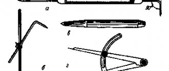
Main types of switches
According to electrical engineering terminology, a switch refers to a device that allows electric current to flow through a circuit. Its distinctive feature is a unique system, the action of which is aimed at quickly breaking contact. All functions of the device are carried out by a manual drive, which reliably turns off the voltage during repair and maintenance work.
There are several types of switches, among which the following can be distinguished:
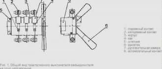
- Reversible (Fig. 1). With the help of these devices, voltage is transferred from one circuit to another. They are mainly used when there is a need to switch the current supply from the emergency section of the circuit to the working one. Special switch rooms are provided for installation of devices. This type of switches has high operational and technical indicators.
- Explosive (Fig. 2). Connects to common output circuits, ideal for private houses, apartments, office buildings. This device is used to connect an object to a common network. They are installed in the electrical panel with the switch lever leading outwards. There is a wide range of models on the market.
- Reversible (Fig. 3). They are used in three-phase electrical networks, ensuring their normal functioning. With the help of these devices, the load is distributed between the lines, and the current is uninterruptedly supplied to consumers. Installation of switches is carried out in a horizontal or vertical position, all switching is done manually. Certain types of devices can be controlled remotely.
The main part of the switch is the rotary contact system. The design of the moving contact is a knife or a spring-loaded fork, and the fixed contact is a knife or two plates, spring-loaded by means of a steel split ring. In addition, the switch is equipped with a handle or manual drive, contact terminals for connecting wires. A 1-way breaking switch with three poles is equipped with three input and three output contacts, and a 2-way changeover switch has six input and six output contacts. For each pole there are 1 or 2 arc chutes, according to the number of directions.
Installation and connection rules
Changeover switches are installed inside distribution boards - ASU. For modular devices, standard DIN rails are provided. The dimensions of the shield are selected according to the number of installed modules. Switches in the usual design are mounted on specially designated mounting panels. A DIN rail can also be used here to accommodate modular protective equipment.
Shields made of plastic or metal are used indoors, and only metal products with the required degree of protection are installed outside.
The main cable supplied from the metering board is connected to one of the inputs of the switching device. The other input is for the backup cable connected to the generator. If the switch has only one output, a cable coming from the distribution panel is connected to it. Modular devices usually have 2 inputs and 2 outputs. The outputs are connected in parallel using jumpers, after which they are connected together to the distribution board.
Such a connection is clearly visible in the example of a single-phase network, to which a three-pole changeover switch is connected, connecting the generator to the electrical network. The main requirement for carrying out such a procedure is to maintain polarity. Correct connection will allow you to avoid changing the positions of phase and zero when making switchings. At the network input, protection is installed in the form of a circuit breaker located in the metering panel. The input coming from the generator is also protected by a machine installed in the panel along with the switch.
Connecting the device can additionally use automatic transfer of a reserve - ATS, or the reserve is switched on manually using an automatic machine. In the case of using changeover switches, such switching is performed without load. First, the load is switched off automatically, and only then all the necessary manipulations with the switch are carried out.
If the design of the switch includes an arc extinguishing device, then switching can be done directly, without first turning off the machine. However, the circuit on all lines must necessarily include fuses or circuit breakers, since the switch itself will not be able to protect the network in an emergency.
Operation of the changeover switch will be safe if you follow the installation rules and recommendations of specialists:
- For installation and further work it is better to use a closed room.
- Switching equipment is reliably protected from moisture and negative external environmental influences.
- The temperature limit at which normal operation is possible is from minus 40 to plus 55 degrees.
- Installation of the changeover switch and its fastening must be strong and reliable.
When installing the device outdoors, you should first ensure protection from external influences. At possible low temperatures beyond the permissible limits, a heating system for the cabinet should be provided in advance. All work on installation, maintenance and repair of switching equipment must be carried out by qualified specialists, with the network completely disconnected.
Installation recommendations
To use the device safely and correctly, the following recommendations must be observed:
- The device must be installed indoors;
- the device must be protected from moisture, as well as from bad climatic conditions;
- the required operating environment temperature for the device ranges from -40 to +55 degrees;
- if the upper part of the contact knife burns, it is necessary to clean it with a file;
- It is necessary that the device is securely and firmly installed.
If the changeover switch is installed outdoors, then it is necessary to ensure protection from environmental influences. It is also necessary to ensure that the device operates within the permissible temperature range - that is, if outdoors, then it is necessary to ensure heating of the cabinet where this switch is installed. Installation, maintenance and repair of the device should only be carried out by a specialist, and only when the power supply is completely disconnected.
Finally, we recommend watching a video that explains in more detail how to connect a changeover switch to the network:
It will be useful to read:
- How to install a diesel generator
- How to connect a three-phase voltage stabilizer
- Connecting the generator to the home network
- What is a load switch used for?
A changeover switch is a special device designed to switch electricity to the necessary devices, operating using a manual drive. Manufacturers offer a wide range of such devices, differing in various technical characteristics.
It is important to remember that there are various options for connecting changeover switches - the choice depends on the characteristics of the electrical network. The most popular switch type switches in residential buildings
To change the operating characteristics of such devices, control units are used.
In addition, these devices have found application in industry when operating backup generators. When choosing a changeover switch for a generator, you need to take into account its configuration and the specifics of the existing grounding.
The quality of operation of the device is ensured by equipping it with a grounding electrode. Its marking indicates the degree of protection. It is optimal if it is IP30.
Types of switches for generators
When choosing products for generators, it is best to give preference to single-module switches. If we are talking about a blocker, then it must be equipped with a classic contact system. The design of reversible blocks often contains a controller. That is why you should not opt for systems with a resonator.
In such situations, the threshold frequency will be high. Products used for generators may vary in size
It is important to pay special attention to the number of capacitors
Before installing generator products, it is necessary to carefully study the grounding system. Full operation of the device is possible in the presence of a grounding electrode. The labeling of the latter must necessarily contain information about the protection system, in most cases this is IP30. Based on this information, you can safely judge the reliable insulation of the device. Such a system will function over many cycles.
Two-way systems
When purchasing changeover switches, it is important to take into account the fact that they can only be used in single-phase circuits. The design must contain two pass capacitors
Manufacturers produce not only two-, but also three-module systems. They can operate with a power supply having a voltage of 300 V. The connection diagram for such a device often involves the use of a meter. Installation is carried out using copper jumpers. Operation of the units is possible in conjunction with expansion switches.
Changeover switches are designed for a voltage of 350 V, the load may vary. The determining factor is the manufacturer. The average load is 30 A.
Three-way modifications
If we look at these changeover switches in detail, it is important to note that they are equipped only with expansion switches. This is the most suitable option for use in two-phase circuits
Products are in wide demand on an industrial scale. Their operation in an enterprise is possible if connected to an electrical panel of the KK202 series.
Often, jumpers are made of copper; blockers may differ in design. A feature of the products is a high sensitivity limit. In addition, they are equipped with a reliable protection system. Insulation comes in different classes. The determining factor when choosing is the manufacturer.
Thus, products of the SFT 250A series are installed exclusively in conjunction with power supplies with voltages of 200 and 300 V. The connection diagram for such devices provides for the use of pass-through capacitors. This is necessary so that the load is no more than 3 Amps. Often systems operate with analog switches. In addition, units manufactured in an expansion version are common.
. When connecting meters, they need to be allocated a special place behind the contact system. Reversing units must be equipped with a resonator and a controller. The choice must be made taking into account the peak frequency of the product.
Generator switches are an effective solution and provide many benefits. In addition to convenient maintenance, it is possible to monitor network characteristics. This minimizes the risk of dangerous situations affecting the functioning of devices connected to the network
When choosing devices, you need to pay special attention to the parameters of the included elements, as well as the room where installation is planned
Two-way modification
When choosing such changeover switches for a generator, you should keep in mind that they can only be used for single-phase circuits. Its design includes 2 pass-through capacitors. For sale you can find not only two-module, but also three-module models. They can work in combination with power supplies having an operating voltage of 300 V. The connection diagram for such a switch may involve the use of a meter. The installation of such a device itself is carried out using jumpers made of copper. Such switches can only work in combination with expansion type switches.
An important point is that electrical panels of any design are suitable for such devices. The changeover switch used for the generator is designed for a threshold voltage, which is 350 V. As for the load parameter, it can have different values. The determining criterion here is the manufacturer of the product. On average, this indicator reaches 30 A.
Application of ABP
The autostart system is more expensive than the manual one, but it constantly monitors the network voltage. When the voltage disappears, the contactor interrupts the connection between the ATS and the central power grid. The starter turns on and the generator starts working. Most generator owners prefer using cheaper partial automation, which works as follows:
- The main power supply is connected through a contactor that opens when the input is disconnected.
- The gas generator is started manually. A time relay is installed in it to warm up the engine and automatically switch to connecting the reserve to the home network.
- When the power supply is restored, the contactor is switched off and the load is supplied again from the public network.
A fully automated power supply system regulates the operation of the gas generator using microprocessors. Video on this topic
Methods for connecting a backup generator
Depending on the specific requirements and capabilities (presence or absence of on-duty personnel, their qualifications, enterprise finances, etc.), the transition to a backup source can be carried out in one of three ways:
- Manual switching.
- Semi-automatic transition.
- Automatic switching.
For small objects and private houses, a manual connection scheme for connecting a gas generator to the home network is quite suitable. The equipment of such systems is inexpensive, and the presence of people in a residential building is implied. The semi-automatic switching method requires operator participation at one or another stage of switching, which means it is perfect for both private homes and facilities with permanent, even unqualified, personnel.
Fully automatic transition is usually used in automated and critical facilities or areas, as well as where there is no permanent staff.
Changeover switch principle of operation
An electrical type device that serves to disconnect an electrical load from one energy source and connect it to another source is called a changeover switch, or a changeover type switch (switch with a midpoint). The devices are available with or without arc arresters. In the first case, network switching can occur with a fully connected load. In the second - only when it is turned off.
The switch is operated manually, that is, if it is necessary to switch power sources, the operator acts on the isolated control lever of the switch. There are also automatic switching systems.
What is a rocker switch
Reversing changeover switch
The purpose of a changeover switch is to transfer voltage between two lines or connect several networks. Using a switch, you can eliminate current leaks during accidents and quickly switch to the entire line. The device is switched using a lever on the front panel, which is moved to 1-2 positions.
The equipment is installed in the switchboard room or near the input panel.
Device specifics
A toggle-type switch is similar to a two-position switch in its operating principle, but is distinguished by increased power and a smooth blade drive. The second difference is the switching process with a line break and operation in three positions:
- apartment/home network;
- shutdown;
- power supply from the generator.
To understand the principle of operation of a changeover machine, you need to understand the design. The middle contact is a rack in the middle with V-shaped knives. The upper and lower terminals are used as side terminals. The middle contact connects only to the upper ones or only to the lower ones. The knives do not have accelerators or springs, so switching from the main to the backup network is done manually.