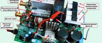
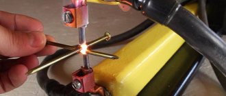
A diode is a semiconductor unit with different conductivities determined by the applied voltage. It has two terminals: cathode and anode. If direct voltage is applied, that is, the potential at the anode is positive compared to the cathode, the unit is open.
If the voltage is negative, it closes. This feature has found application in electrical engineering: the diode bridge is actively used in welding to rectify alternating current and improve the quality of welding operations.
Types of devices, their features
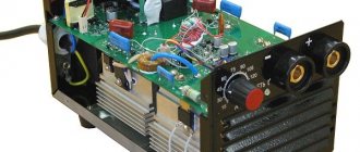
DIY welding rectifier
A homemade welding rectifier is needed to effectively power a household or industrial structure with small volumes of work and work cycles.
In industry, more powerful equipment is used; operations with it do not create pauses during welding.
During this period, the hot parts cool down, the speed of the procedure decreases, which does not interfere with home appliances.
These products consist of elements:
- transformer
- capacitor unit
- rectifier
When starting to create a welding device, the master needs to decide on the direction of work and its dimensions.
The following depends on the volume of production and the number of connections:
- selection of the necessary electrodes
- system parameters
- material characteristic
The assembler, having selected the necessary diagram and materials, and having assembled the device step by step, will achieve the necessary indicators in the system.
Possible details when creating a welding machine
Welding rectifier circuit.
When creating a welding machine with your own hands, the stability of the electric arc is achieved by constant potential. The stability of the arc ensures the quality of the resulting seams. Constant potential is achieved by using high-power rectifiers, which are carried out on diodes that can withstand currents of up to 200 A, such as, for example, the B-200.
These diodes are large in size and require mandatory use to organize high-quality heat removal from massive radiators. This circumstance must be taken into account when manufacturing the structure body. The best option when creating a design would be to use a special diode bridge. The diodes can be mounted in parallel, which significantly increases the output current.
When assembling a structure with your own hands, you need to adjust all its components. If the selection is poor or incorrectly calculated, the design can affect the quality of welding.
Sometimes, with the appropriate selection of parts and components, a truly unique device can be obtained, which has a soft and easy ignition of the electric arc, and parts can be welded even with very thin walls, with almost no splashing of liquid metal.
What is good about the device and what hinders it?
How to convert an AC welding machine into a DC welding machine - the necessary semiconductor circuit with a rectifier device will answer this question for the master:
- The three-phase system has the best performance; it allows you to use network power up to 380 V.
- Such equipment is used where a large continuous process is needed in order to weld large steel parts without interruption during this time period. With the help of these powerful devices you can produce gates, containers, and any utility metal structures.
- Such a tool will be useful mainly not in a private household, but for small businesses and the sale of manufactured products. This is because these are bulky and heavy structures, unlike devices with fewer phases, they require additional installations to move the device.
In such a system, the transformer is capable of reducing weight, but you need to be able to wind its core yourself or buy a ready-made one with the necessary parameters.
Welding rectifier design - let's start with theory
Household welding machines are low-power rectifiers and inverters, with a relatively low rated welding current. Having a long pause for cooling between periods of work, they are ineffective when performing large volumes of work in industry and production. The only niche occupied by such units is household use, as well as small-scale contracting business.
The classic layout of the welding machine includes:
- a step-down transformer;
- rectifier (bridge made of semiconductor elements);
- capacitor block (to smooth out ripples at the converter output).
Before manufacturing or purchasing any tool, be it a construction level or a hammer drill, or we have a welding machine, it is necessary to determine what types of work it will perform. The weight and dimensions of the device, the standard size of the electrode used and, accordingly, the thickness of the sheets of metal being welded directly depend on this.
The best indicators for the quality of output current are three-phase devices connected to a 380 Volt network. They can work longer without interruptions for cooling, and also work with more massive steel structures within 200-400 Amperes. Ideal for welding containers, stalls, garage doors. This is what you need for small businesses.
A significant drawback is limited access to the power supply. Not all holiday villages and garage communities can boast access to such power communications. In addition, a welding machine with a three-phase transformer will be 1.5-2 times heavier than its single-phase counterpart. The total weight of the device will easily exceed one hundred kilograms. One person cannot bear such a weight; it becomes necessary to mount wheels for movement or use a toroidal transformer, which will reduce the total weight by 20-40 percent. But it is worth considering that you will have to wind it yourself.
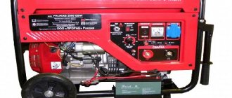
A single-phase welding rectifier for welding, mounted on a single-phase transformer designed for a 220 Volt network, is much lighter. Its weight depends 90% on the weight of the step-down transformer and will be in the range of 30-80 kilograms. This equipment can operate at currents of 125-180 Amps, providing a high-quality weld when welding simple structures - gates, awnings or a manual concrete mixer. The ease and accessibility of the electrical network make single-phase devices extremely mobile. They can work not only on the upper floors of high-rise buildings, but also where there is no electricity at all, powered by a gasoline generator.
Requirements for structural assembly
The circuit for a simple rectifier is not particularly complicated; you will need conductors that pass the electrical flow and are directed in the right direction.
Welding rectifier circuit
Electrical parts should be prepared from the following configuration:
- diodes - they allow the circuit to operate without control units
- thyristors that supply signals to elements for good electrical passage
- flows, when they decrease, the valves close
- transistors that control all processes with voltage
- resistors that allow you to regulate the current
In order for electrical elements to serve longer in operation, they are selected with high parameters, while ensuring that the actual current in the circuit is less than the specified nominal value.
The welding rectifier is assembled using the following items:
- transformer
- diode
- radiator
- throttle
- electrode
- capacitor
- ceramic core
- nickel wire
The assembled semiconductor circuit in the form of a diode rectifier is installed with a radiator that provides heat exchange and cooling. A choke is provided for the falling characteristic of the electric current, an increased resistance or a rheostat is used to regulate the required parameters. The poles, positive and negative, are connected to the electrode and the object.
The function of the electrolytic capacitor in the circuit serves to implement smoothing filtering and reduce ripple.
Many specialists independently cope with winding rheostats on ceramic cores. Use nichrome or nickel wire. Their diametric selection depends on the magnitude of the welding current flows.
Rheostatic resistance is calculated based on the wire parameters:
- resistivity
- section
- length
Adjustment of the welding current depends on the number of turns.
DIY welding rectifier
A rectifier for a welding machine is built around semiconductor elements, the essence of which is to pass electrical currents in only one direction. Today, three devices can be used in rectification circuits:
- diode (the best because it is the simplest; when using it, there is no need to introduce control units into the rectifier circuit);
- thyristor (for current to flow, it must receive a signal from the control system; when the passing current drops to zero or the voltage across it becomes less than in the next phase, the valve closes);
- transistor (a fully controllable “valve”, to open and close which you need to send a signal to the control electrode, and also the most expensive element).
Operating principle of a single-phase bridge circuit
The process of alternating current flow can be represented as a wave oscillating at a certain frequency. This procedure is very fast, which can be imagined as at one specific moment, a current passes first in one direction and then in the other.
In welding, specialists ensure that these movements are carried out unilaterally:
- A semiconductor is soldered into the secondary winding of the transformer; it carries out electrical transmission in the desired direction, which is direct current. Since alternating current has frequencies, its waves will create pauses that are unacceptable in the work process.
- In the circuit, the electrical components are soldered in the opposite direction with respect to each other, then the electron flow will flow in the opposite direction.
- If you create a circuit with pairs of elements directed towards each other, you will get a flow of waves oscillating from zero to maximum. This limit is calculated on the possibility of a secondary transformer winding.
- In the same way, fluctuations are obtained that decrease to a minimum, from the moment of which a new rise begins. In this case, a plus pole voltage is generated, and its minus is located in the transformer winding.
- This circuit is used with an output device in place, so as not to disassemble the winding; it can be created by winding it yourself. This design is famous for its efficiency in relation to the number of semiconductor elements.
- Dividing the winding into several sections allows you to use only part of it.
- The most convenient and applicable for electrical engineers is the bridge rectifier structure. A similar plan consists of a square with semiconductors on the sides. Some of its corners output direct current, others show the voltage output from the transformer.
This example has the advantage that it does not require creating a lead from the second winding, but it will require a lot of semiconductor gates. Welding will be with low power; electrodes of special sizes are selected for them, and parts with limited parameters are welded. It should be taken into account that the parallel connection of a capacitor device reduces wave vibrations during operation of the welding machine.
Advantages and disadvantages
The devices are characterized by high power in a small size. The most compact ones are inverters. These generating devices are usually classified as a separate group. In them, the transformer occupies no more than 1/5 of the volume.
The main difference between other welding rectifiers and transformers is the ability to generate direct current instead of alternating current. The main advantages of rectifiers are associated with this ability:
- when a unipolar charge is applied to a melting electrode, it flares up faster;
- energy losses are reduced - the efficiency of the transformer is much lower;
- arc combustion is stabilized;
- with uniform melting of the rod in the melt bath, fewer splashes occur, injuries and the risk of accidental fires are reduced;
- it is more convenient to control the seam, it turns out even;
- welding capabilities are expanding;
- The consumption of filler materials is reduced; with a large volume of work, the savings are noticeable.
Along with the advantages, most rectifiers have disadvantages:
- There are still power losses;
- when the network voltage drops, they work worse;
- can fail even during short circuits in the power supply network;
- Many models are afraid of humidity and dust.
Distinctive features of three-phase equipment
The operating principle of the device, assembled according to an electrical circuit for a rectifier powered by three mains phases, is based on the presence of a small ripple in the output voltage. The waves overlap each other in the process, preventing the voltage from dropping to zero.
The welding installation is constructed by including semiconductors behind the transformer windings in phases. The terminals are connected, resulting in a single output. Through such a bridge, waves divided in two are passed, forming a rapid pulsation, but with less force. In such a design, you will need a zero output, and the transformer is connected to the power supply according to a special circuit.
Craftsmen know in practice that the highest quality work is obtained with the use of devices operating on direct current, providing an arc with stable combustion and a durable seam. In order to obtain the necessary parameters, despite the growth of technological discoveries and the emergence of innovations in instrument making, craftsmen with their own hands produce and still use the simplest rectifiers.
What type of welding are they used for?
Most welding technologies are produced using this equipment. These include MMA (manual arc welding with a coated electrode), MIG (fusion gas welding), TIG (non-consumable electrode argon arc welding). The use of rectifiers makes it possible to weld not only ferrous metals, but also stainless, heat-resistant and heat-resistant high-alloy steels, cast irons, non-ferrous metals, aluminum and titanium alloys.
What electrodes are used
Welding can be done with any type of electrode:
- DC welding electrodes (for example: UONII-13/55 or UONI-13/55);
- universal electrodes (for example: ANO-4, MR-3 or OZS-12);
- special electrodes.
Calculation of the cross-section of the wires of the primary winding of the transformer
Diagram of a welding transformer.
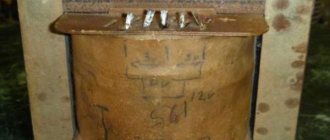
The theory of transformers is complex in that it is based on the laws of electromagnetic induction and other phenomena of magnetism. However, without using complex mathematical apparatus, it is possible to explain how a transformer works and whether it can be assembled independently.
The transformer can be manually wound on a metal core assembled from transformer steel plates. It is easier to wind on a rod or armored core than on a toroidal one.
You should immediately note that the image clearly shows the difference in the thickness of the wires: the thin wire is located directly on the core, and a larger number of turns is clearly visible in it. This is the primary winding.
The thicker wire with fewer turns is the secondary winding.
Without taking into account the power losses inside the transformer, let's calculate what the current I1 should be in its primary winding.
The ideal network voltage is U=220 V. Knowing the power consumption, for example, P=5 kW, we have:
I1 = P:U= 5000_220=22.7 A.
Based on the current in the primary winding of the transformer, we determine the diameter of the wire. The current density for a household welding transformer should be no more than 5 A/mm2 of wire cross-section. Therefore, for the primary winding you will need a wire with a cross section of S1 = 22.7:5 = 4.54 mm2.
Using the cross-section of the wire, we determine the square, its diameter d without taking into account the insulation:
d2=4S/π=4×4.54/3.14=5.78.
Taking the square root, we get d=2.4 mm. These calculations were performed for copper wire cores. When winding wires with an aluminum core, the obtained result must be increased by 1.6-1.7 times.
For the primary winding, copper wire is used, the insulation of which must withstand high temperatures well. This is fiberglass or cotton insulation. Rubber and rubber-fabric insulation is suitable. Wires with PVC insulation should not be used.
Calculation of the cross-section of the wires of the secondary winding of the transformer
The voltage at the output of the welding machine transformer in the absence of a welding arc (idle mode) is usually 60-80 V. The higher the idle voltage, the more reliably the arc is ignited. The welding arc voltage is usually 1.8-2.5 times less than the no-load voltage.
Attention. It is necessary to constantly remember that in the absence of an arc the voltage at the transformer output is life-threatening.
For welding in everyday life, an electrode with a diameter of 3 mm is usually used, which is sufficient to provide an arc current of approximately 150 A. With an open circuit voltage of 70 V, the arc voltage will be approximately 25 V, and the power consumption P of the welding machine must be at least
Р=25×150=3750 W =3.75 kW.
It is advisable to design the transformer for higher power, that is, higher welding arc current. For example, with an arc current of 200 A, the power consumption will be approximately 5 kW. This is the power the transformer should be designed for.
The single-phase voltage in the house should be 220 V, but it can vary by ±22 V. This is one of the reasons why the arc current may change and will need to be adjusted.
The cross-section of the wire in the secondary winding of the transformer is determined based on the current density equal to 5 A/mm2. For a current of 200 A, the wire cross-section is 40 mm2, that is, it can only be a busbar that is wound with layer-by-layer insulation. Based on existing standard sizes, you can select the required tire both in length and cross-section.
Typical sizes of copper busbars produced by industry:
- length from 0.5 to 4 m with intervals of 0.5 m;
- width from 2 to 60 cm with intervals of 1 cm (with widths from 4 to 10 cm) and with intervals of 5 cm (with widths from 10 to 60 cm);
- thickness from 3 to 10 mm.
You can also use a stranded wire, the cross-section of which corresponds to the calculated value. To increase the cross-section, the wire can be folded in half or three. For aluminum wire, the cross-section must be increased by 1.6-1.7 times.
For a choke that is connected at the output of the transformer, the cross-section of the wire must be the same as in the secondary winding of the transformer.
Methods for adjusting current in rectifiers
To change the ampere value in the welding converter, several control options are provided. Most rectifiers have step adjustment due to a sectioned connection of the primary winding. This switch is installed in the form of a handle, with two or three positions. If it is necessary to immediately increase the current strength until it is possible to weld thick plates or cut, then part of the primary winding is “cut off” and the current flows according to a shortened circuit. To return the voltage in the opposite direction, the circuit switches to a longer part of the primary winding, and the current becomes less, which is convenient for welding thin sheets.
In addition to the coarse adjustment affecting the transformer, rectifiers use fine tuning using a saturation choke. It is installed between the silicon diodes (rectifier block) and the step-down transformer. An inductor is a series of coils through which voltage passes. By switching the control lever, the length of the current path in the windings and its strength changes.
Most converter models have a handle on the housing cover, which drives the screw shaft and platform with the secondary winding of the transformer. Changing the distance between the windings also serves as a way to adjust the current.
The most effective for changing the welding voltage is a thyristor unit. Its implementation in the circuit allows you to control the length of the voltage supply and its effect on the metal. Thanks to thyristors, it is possible to simulate rigid, flat-sloping and steep-sloping current characteristics.
Adding a rectifier
A homemade powerful welding transformer from a circuit design point of view is a regular power supply. Accordingly, the rectifier is designed as simply as in a network charger for a mobile phone. Only the element base will look several orders of magnitude more massive.
As a rule, a pair of capacitors are added to a simple diode bridge circuit to dampen rectified current pulses.
You can assemble a rectifier without them, but the smoother the current, the better the quality of the weld. To assemble the bridge itself, powerful diodes of the D161–250(320) type are used. Since a lot of heat is generated on the elements when loaded, it must be dissipated using radiators. The diodes are attached to them using a bolt connection and thermal paste.
Of course, the radiator fins must either be blown by a fan or protrude above the case. Otherwise, instead of cooling, they will heat the transformer.
Mini welding transformer
If you do not need to weld rails or channels from 4–5 mm steel, you can assemble a compact welder for soldering steel wire (making frames for homemade products) or welding thin sheet metal. To do this, you can take a ready-made transformer from a powerful household appliance (the ideal option is a microwave) and rewind the secondary winding. Wire cross-section 15–20 mm², power consumption no more than 2–3 kW.
The calculation of the circuit is carried out in the same way as for more powerful units. When assembling the rectifier, you can use less powerful diodes.
Micro welder
If the scope of application is limited to soldering copper wires (for example, when installing distribution boxes), you can limit yourself to a design the size of a pair of matchboxes.
Performed on transistor KT835 (837). The transformer is manufactured independently. In fact, it is a high-frequency boost converter.
Unlike traditional welders, this circuit uses high voltage, up to 30 kV. Therefore, care should be taken when working.
We wind the transformer on a ferrite rod. Two primary windings: collector (20 turns 1 mm), base (5 turns 0.5 mm). Secondary (boost) winding - 500 turns of 0.15 wire.
We assemble the circuit, solder the resistor circuit according to the circuit (so that the transformer does not overheat at idle), the device is ready. Power supply from 12 to 24 volts, with the help of such a device you can weld wire harnesses, cut thin steel, and join metals up to 1 mm thick.
A thick sewing needle can be used as welding electrodes.
Design and principle of operation
The classic design is represented by a combination of several devices that provide control of current indicators. The main blocks can be called:
- diodes;
- a step-down transformer;
- cooling system, which is often represented by a fan;
- instruments for measuring current indicator;
- regulators of various types.
The device of the welding rectifier allows for high-precision adjustment of current indicators. Unlike the design of a transformer, it can not only increase the current strength, but also make the indicator constant, due to which high arc stability is ensured.
Welding rectifier device
The operating principle of the welding rectifier has the following features:
- The incoming current is initially applied to the primary winding of the built-in step-down transformer.
- Due to electromagnetic induction, the process of decreasing the voltage value and increasing the current on the secondary winding occurs. The circuit of a modern welding rectifier determines the maximum voltage value at idle 48V.
- The generated voltage is supplied to the installed diodes. New models are manufactured using silicon-based diodes. They are installed as a semiconductor, which ensures current flow in only one direction. It is due to diodes that a constant voltage is ensured, since they eliminate fluctuations during the reverse flow of electricity.
- It is worth considering that during operation the diodes heat up significantly. That is why all models of welding rectifiers have a cooling system, which in most cases is represented by fans. When the device is actively used, constant airflow allows you to reduce the temperature of the semiconductors used. Some models are equipped with a sensor that detects system overheating.
- Sensors are installed to monitor voltage. They work in conjunction with the machine and can turn off the device automatically when the voltage is high.
- The regulator is installed so that you can select the voltage depending on the thickness of the metal being welded.
It is quite difficult to create a welding machine rectifier with your own hands, since for this you need to have certain skills in working with electrical engineering. Industrial versions have high operating accuracy and reliability, which will determine their high popularity.
The features of the installed adjustment devices include the following points:
- In most cases, the adjustment is stepwise. It is represented by a sectional winding connection.
- With step adjustment, the step matters. A lever is installed to control the sectional connection of the winding.
- Most models for using high currents have a design that involves cutting off part of the winding. Due to this, the current is supplied in a short circuit.
The above setting is quite rough. There are models with fine tuning, which is based on the use of the choke saturation method: a device is installed between two silicon diodes and a step-down transformer. A choke is a design represented by a combination of several coils through which current is also supplied during operation of the equipment. By switching the position of the regulator, the length of the winding path also changes.
Most models have a large handle on the body, due to the movement of which the screw shaft with the secondary winding of the transformer is driven. By changing its position, the length of the path that the current overcomes is also adjusted. However, this setting is also characterized by low accuracy.
Welding rectifier circuit
Almost all welding rectifiers have a control unit in the form of a combination of various levers and switches. By changing their position, the characteristics of the supplied current are adjusted.
Core Assembly
So, the wires are selected and prepared. Now we need to assemble that same core. The image below shows an ideal core for a homemade transformer in all respects. It is rod type.
For assembly you will need plates made of electrical steel. The optimal thickness of one plate is no less than 0.35 and no more than 0.55 mm. And the required core size (a, b, c, d in the figure above) is calculated separately based on the cross-section of the wire. But many craftsmen choose sizes “by eye”. The main thing is that all the turns fit.
Now let's start assembling the core. Take the plates (they should be L-shaped) and fold them in the order shown in the image below. When you have a core of sufficient thickness, fasten all the plates at the corners with bolts. Process the records using a needle file. Then insulate the core.
How to connect a ballast, ballast rheostat
Ballast rheostat (ballast) is a circuit device with a welding rectifier, with the help of which the welder adjusts the current. The regulation principle is based on the action of Ohm's law, known in electrical engineering. The higher the resistance that the ballast represents, the lower the current.
Ballast rheostat Ballast rheostat Brima RB-302. Photo VseInstruments.ru
Typically, a ballast is a spring, the efficiency of which depends on the optimally selected length of the spring, the diameter of the coils and wire, as well as the material from which it is made. A regulator contact is connected to the spring, moving it in the direction of winding changes its resistance, and therefore the current strength. The regulator contact is connected to the wire of the welding machine holder. The other end is connected to the power supply.
Winding
The next stage is winding the transformer. First, the primary winding is wound. It is necessary to make about 210-215 turns. You need to wind it as shown in the image below. When you have made all the turns, attach a textolite plate on top. The ends of the winding can be secured to it using bolts.
Next you need to rewind the secondary winding. It is necessary to make about 70 turns on it. Then attach the textolite plate in the same way and secure the ends of the winding to it using bolts. Ready! The transformer can be used in this form, or can be used for further modifications. The image below shows the final view of the wound transformer.
Installation
When using a parallel circuit for connecting diode bridges, it is necessary to take into account that they all have some variation in parameters.
Therefore, when selecting elements, it is necessary to do this with some margin of safety. If this requirement is met, a more compact diode bridge can be obtained for the welding machine than when using single diodes.
Diode assemblies allow them to be placed on one radiator, since the cases are not energized. This allows you to install them anywhere, even outside.
Depending on the required welding current, the rectifier may require 3 to 5 diode assemblies. For better heat transfer, diode bridges are installed on the radiator through heat-conducting paste.
It is recommended to connect conductors to the contacts by soldering, otherwise there may be power losses at the contact point and its strong heating.
Features of operation
Operation of welding rectifiers requires knowledge of electrical safety during maintenance. The rectifier can only be turned on if it is properly grounded through a circuit breaker. It is necessary to use a working network cable with grounding protection.
During work, you need to use only the whole welding cable. Do not touch live parts with exposed areas of the body. The device must not be used for other purposes. Before connecting the device to the network, you must read the operating instructions, which may vary slightly depending on the type of device and the features of the specific model.
To ensure high-quality and long-term operation, equipment must be properly maintained and repaired in a timely manner.
It is important to check conductive elements for insulation integrity. Do not operate the device without a special protective casing
If necessary, you need to adjust the current in the rectifier.
Before connecting the device to the network, it must be cleaned of dust. In addition, it must be checked for compliance with the passport instructions. Next, the housing is grounded, as well as the terminal of the secondary network that goes to the product. Then you need to check the operation of the fan
It is important to monitor the serviceability of contacts, thermal protection, arcs, parts
The installation of the device must be carried out by a qualified specialist. Welding can be carried out by a welder who has been trained in working with the device and has an electrical safety group of at least 2. During operation, the unit is promptly cleaned of dust and dirt. In addition, it is purged with compressed air, filling the surfaces subject to friction with refractory lubricant.
During operation, it is necessary to protect the unit from precipitation, pollution and dampness. If necessary, it can be installed on construction sites. However, this can only be done in special mobile rooms. If possible, the device should be protected from mechanical shock. During breaks in operation, the rectifier must be turned off.
If the product is installed in a workshop, a specially designated area is fenced off for it. If there is no required voltage, this indicates a malfunction. For example, this happens due to problems with the wind relay, as well as air being sucked in from the wrong direction, or valve breakdowns. If the electric motor does not work, it is necessary to check the unit for an open circuit.
The following video explains how to choose a welding machine.
Application in practice
For example, consider the TELWIN Force 165 inverter device. The input rectifier uses GBPC3508 diode assemblies. The GBPC3508 bridge rectifier can operate with a current of 35 A, reverse voltage - 800 V.
Along with it comes a necessarily smoothing filter made of large capacitors. In addition, there is an electromagnetic compatibility filter that prevents interference from the inverter into the household network.
The output of the inverter uses powerful dual diodes with a common cathode. They have high performance, unlike diodes located at the input of the device.
Thanks to the short recovery time, less than 50 nanoseconds, the devices have time to switch the high-frequency current at the output of the secondary winding.
This device uses dual diodes STTH6003CW, FFH30US30DN or VS-60CPH03, designed for a forward current of 30 amperes for one device (60 amperes for both) and a reverse voltage of 300 volts.
Installed on the radiator. An RC filter is used to protect semiconductors from overload. The control circuit requires a stable power supply without voltage surges.
For this purpose, the device is equipped with zener diodes or a ready-made integrated stabilizer, which provide stable power to the control chips. The result is a compact device that allows high-quality welding of metal.
Pros and cons of equipment
As previously noted, during operation, a transformer can also be used instead of a rectifier. The advantages of a welding rectifier are the following:
- You can get a more stable arc. During welding work, the characteristics of the resulting arc largely determine the quality of the seam. The equipment under consideration is characterized by the fact that it provides a more stable arc burning. That is why it has become widespread recently.
- The advantages of a welding rectifier also lie in the fact that after the work is completed, an even seam with a fine scaly pattern is obtained. Due to this, the scope of application of such equipment has been significantly expanded.
- The low tendency to form splashes of molten metal significantly simplifies the task and improves the quality of the result obtained.
- High degree of efficiency. As previously noted, the use of the equipment in question can significantly reduce the melting rate of the electrode.
In addition, the welding rectifier is more suitable for joining non-ferrous and alloyed metals, which may have different performance qualities.
The disadvantages of welding rectifiers are largely related to its rather high cost and the need for transportation. It is worth considering that to ensure a long service life of the device, you should pay attention to its condition before each use. The service includes:
- Checking the reliability of fixation of the terminals used.
- Removing accumulated dust.
- Checking the insulation of all conductive elements.
As for frequent breakdowns, often their signs are a strong hum during operation of the device or its heating. If you observe such symptoms, you should check the condition of the device, as the reasons for their occurrence may be:
- Deformation or complete stop of the cooling system fan. It is worth considering that improper operation of the cooling system can lead to serious problems.
- Short circuit of the primary winding or violation of the insulation of the core sheets.
- A decrease in output voltage occurs due to a short circuit or break in the secondary winding.
In conclusion, we note that modern straighteners make it possible to obtain high-quality seams when connecting various metals. A large number of positive qualities determined the widespread distribution of the device. There are a wide variety of designs available for sale, each with exceptional performance.
Design of transformer and chokes
Wire winding diagram.
T1 is assembled from 3 “lines” from old TVs, folded together. Core PK30x16 made of ferrite grade 3000NMS-1. Windings “I” and “II” each have 2 sections with PSD 1.68 wire insulated with fiberglass. They are connected in series and have turns:
- winding “I” - 2×4;
- winding “II” - 2×2.
Winding “I” operates in the worst thermal conditions, so during assembly it is necessary to wind it with a pitch (gap) of 1 mm. In the second winding, do not forget to tap from the middle.
Both windings must be placed in such a way that the operation of the diodes VD11-VD34 is not disrupted. The winding direction of winding “I”, starting from the terminal connected to L2, is counterclockwise. And the winding direction of winding “II” is clockwise, from the terminal connected to VD21-VD34.
Winding “III” is a turn of wire 0.4-0.5 mm in insulation for a voltage of 500 V or more.
It is important to distribute the windings, maintaining the gaps correctly. This is necessary for cooling the magnetic circuit and for safety reasons. To do this, install 4 fiberglass (1.5 mm) plates, which are glued after adjustment.
Inductor L1, with an inductance of 40±10 μH, is wound on a PL core 12.5×25-50 with a gap (non-magnetic) of 0.3-0.5 mm and has 175 turns wound with PEV-2 type wire, caliber 1.32.
Choke L2 is a spiral without a frame, wound with 4 mm2 wire in thermal insulation. Number of turns -11, winding diameter -14 mm. A large current flows through the inductor and it needs to be blown through.
Calculation of the number of turns
The number of layers for each winding is determined from the core area using the formula K = 50: Sc = 50/45 = 1.11 turns per volt.
Attention! In this formula, as well as in the first, the coefficient of 50 is adopted for transformers with cores of types P and Sh., for ring cores it will be equal to 35 for, ShL and ShP - 40.
Now we determine the maximum current on the primary winding using the formula: Imax = P: U = 6750: 220 = 30.71 A. Based on these data, you can find out the number of layers for winding. The calculation is carried out using the formula Wx = Ux * K. For the secondary, it will be W2 = U2 x K = 60 x 1.11 = 67 turns.
We will find out the number of layers of the primary winding later because To do this, you need to apply a different formula. To adjust the output power, several outputs are made from the primary winding. The number of turns for the primary winding is found by the formula: W1st = (U1 x W2): Ust, vit.
Where:
- Ust – voltage on the secondary winding.
- U1 – voltage of the primary winding;
- W2 – number of turns of the secondary winding;
- W1st – the number of primary windings of a certain stage.
But first it is necessary to calculate the voltage of each stage Ust. To do this, we use the formula U=P: I, B.
Using the formula U = P: I, V. for the original design transformer P = 6750 W, we calculate the data for four stages with a power of 95 A, 110 A, 135 A and 165 A. Substituting the data into the formula, we obtain U1st1 = 6750:95 = 71 V, U1st2=61 V, U1st3=50 V, U1st4=41 V.
Next, we use the obtained data to calculate the winding. According to the formula W1st = (U1 x W2): Ust, vit. we get the number of turns for each stage (rounded up) W1st1 = (220x67): 71 = 208 turns, W1st2 = 242 W1st3 = 295 turns, W1st4 = 359 turns.
By adding a value of 6% to the larger number of turns, we obtain the required calculated total number of turns of the primary winding W1 = 359 + 18 = 377.
Finally, let's calculate the cross-section of the wire on the primary and secondary windings. To do this, divide the maximum current for each winding by the current density. As a result of the calculation: Ssecond = 165: 3 = 55 mm2, Sfirst = 11 mm2.
As a result, the calculation of a welding transformer powered from a single-phase network U1 = 220V, with a power of 6.75 kW. we get:
Iron: U-shaped stamped sheets of transformer steel 0.5 mm thick Type of windings - circular wound on a frame; Number of turns W1 = 377 V., W2 = 67 V., Number of adjustable steps - 4. at Ireg - 95 A, 110 A, 135 A and 165 A. Wire cross-section Ssecond = 55 mm2, Sfirst = 11 mm2
Electrothermal installations, electric arc welding installations
| Equipment for electrical installations |
- General information
- Electrothermal installations
- 1. General information about electrothermal installations
- 2. Electrical resistance heating installations
- 3.Induction heating electrical installations
- 4. Electrical arc welding installations
- 5.Electrical installations of high-intensity heating
- Electrochemical and electrophysical installations
- 1.Electrolysis plants
- 2.Electrochemical installations
- 3. Electroerosive installations
- 4.Electrochemical-mechanical installations
- Electromechanical installations
- 1. Magnetic pulse units (MPU)
- 2. Electromagnetic installations (EMU)
- 3.Electrohydraulic units (EGU)
- 4.Ultrasonic units (USU)
- Electrokinetic installations
- 1.Electric filters
- 2. Installations for separating bulk mixtures
- 3. Installations for separating emulsions and suspensions
- 4.Desalination plants
- 5.Electrostatic painting installations
- …
| • Site overview • |
- Electrical equipment up to 1000 V
- Electrical apparatus
- Electric cars
- Operation of electrical equipment
- Electrical equipment of electrical technological installations
- Electrical equipment for general industrial installations
- Electrical equipment for lifting and transport installations
- Electrical equipment of metalworking machines
- Electrical equipment above 1000 V
- High voltage electrical apparatus
- Electrical engineering
- Electric field
- DC electrical circuits
- Electromagnetism
- DC Electrical Machines
- Basic concepts related to alternating currents
- AC circuits
- Three-phase circuits
- Electrical measurements and instruments
- Transformers
- AC Electrical Machines
- Electrical installation
- Where does electrical installation of power supply of electrical equipment and wiring begin?
- Electrical wiring installation
- Calculation of power consumption, cable cross-section and circuit breaker rating
- Electrical installation work and cable laying in residential and non-residential premises
- Electrical installation work on disconnecting junction boxes and electrical equipment
- Electrical installation and grounding of sockets
- Electrical installation of potential equalization
- Electrical installation of the ground loop
- Electrical installation of a modular pin ground loop
- Electrical installation of heating cable for underfloor heating
- Electrical installation work on laying cables in the ground
- Electricity in a private house
- Power supply project
| • Electrical equipment • |
- Electrical equipment up to 1000 V
- Electrical apparatus
- Electric cars
- Operation of electrical equipment
- Electrical equipment of electrical technological installations
- Electrical equipment for general industrial installations
- Electrical equipment for lifting and transport installations
- Electrical equipment of metalworking machines
- Electrical equipment above 1000 V
- High voltage electrical apparatus
ELECTROSPETS
ELECTROSPETS
AC Welding Arc Power Sources
DC Welding Arc Power Sources
Schematic diagram of the welding rectifier VDU-504
The main element that ensures the arc welding process is the welding arc power source. Since welding is possible on both alternating and direct current, it is necessary to have sources of alternating, direct and rectified current.
AC Welding Arc Power Sources
AC welding arc power sources are welding transformers, single- and three-phase. Depending on the number of welding stations supplied, there are single and multi-post welding stations. The number of welding stations connected to the transformer (n) is determined from the ratio:
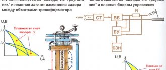
According to the method of obtaining the falling external I-V characteristics and regulating the current, there are two types of power sources: - transformers with normal magnetic dispersion and a choke current regulator (separate or built-in), - transformers with increased magnetic dispersion and coil, shunt or turn step current regulators. Devices with normal magnetic dispersion (Fig. 1.2-32) are made in two types: with separate (a) and built-in (b) current regulators (RT). A welding machine with a separate RT consists of a core (2) on which the primary (1) and secondary (5) windings are located. A voltage of -220 V or -380 V is supplied to the primary winding, and the secondary creates an open circuit voltage of 60...65 V and is connected in series with the reactive winding (3) of the current regulator. RT - choke (Dr), consisting of a fixed magnetic circuit (6) with a winding (3) and a movable (4) magnetic circuit, between which there is a gap “δ”.
The resistance (inductive) of the RT can vary over a wide range when the air gap changes using a screw mechanism (local or remote control). As the gap increases, the inductive reactance “Dr” decreases, which leads to an increase in the welding current, and vice versa. The presence of a reactive winding provides a falling external current-voltage characteristic, due to which the arc voltage changes in accordance with fluctuations and changes in its length. A welding machine with a built-in RT is distinguished by the fact that all three windings are located on the same magnetic core. The advantages of transformers of this system include their compact design, lower consumption of copper and transformer steel. When regulating the current from the maximum to the minimum value, the open-circuit voltage slightly increases, which increases the stability of the arc. According to this scheme, transformers of the TSD and ST types are manufactured for 1000 and 2000 A. They have several stages of changing the open-circuit voltage of the secondary winding (U2.0) by switching taps on them and are designed for automatic submerged arc welding. TSD-500 is used for both automatic submerged arc welding and manual welding. It has the following indicators: In = 500 A, U2.0 = 80V, PV = 60%, welding current control range from 200 to 600 A. Devices with increased magnetic dispersion (Fig. 1.2-33) are made with a moving (a) coil , with a magnetic (b) shunt, with a shunt and magnetization (c).
All transformers have primary (1) and secondary (3) windings, a magnetic circuit (2) and various devices for regulating the current. The moving coil (a) is located on the magnetic core and slides along its rods, moving manually using a screw mechanism. When approaching the primary (fixed) coil, the leakage inductance decreases, which leads to an increase in the welding current. The majority of welding transformers of the “TS” type (for currents from 120 to 500 A), “TSK” and “TD” (for currents of 300 and 500 A) are built on this principle. Unlike "TS", "TSK" transformers have capacitors connected in parallel with the primary winding, which increases the cos φ of the network. Transformers of new types “TD” have a range switch, with the help of which the coils of both windings are switched from parallel connection to serial connection, which provides 2 ranges of welding current changes. For example, TD-504 with a rated current of 500 A has the following indicators at PRnom = 60%:
- range 1. U2.0 = 60 V, regulation limits from 240 to 750 A; - range 2. U2.0 = 70 V, regulation limits from 75 to 240 A.
Transformers of types TS, TSK and TD are designed for manual arc welding. The magnetic shunt (b) is located in the window of the magnetic circuit between the spaced apart coils of the primary and secondary windings. When the shunt (4) is rotated, the leakage inductive reactance changes. If the gap between the magnetic core (2) and the shunt (4) decreases, then the welding current also decreases and vice versa. Transformers of the “STSh” type (for currents of 250, 300 and 500 A) are built on this principle. Some of them have switches for coils of sectioned windings from parallel to serial connection and a device for disconnecting the transformer from the network 0.5... 1.0 s after stopping welding. The disconnecting device eliminates prolonged idling, which ensures an increase in the cos φ of the network. Transformers of the “STSh” type are designed for manual arc welding and automatic submerged arc welding. A shunt with bias (in) direct current is located in the window of the magnetic circuit between the spaced apart coils of the primary and secondary windings. On the stationary shunt (4) there is a magnetized winding (5), by changing the current Iп in which the leakage inductive reactance of the main windings can be adjusted. At Ip = 0, this resistance is minimal, and the welding current is greatest. An increase in Ip leads to a decrease in welding current. Transformers of new types TDF are built on this principle (for currents of 1000 and 1600 A at PVnom = 100%). Transformers allow for step-by-step regulation of the welding current. Stepped (coarse) regulation is achieved by switching the coils of the sectioned secondary winding from parallel to series connection. Smooth (fine) regulation - by changing the current Ip in the winding (b), receiving power from a single-phase thyristor rectifier. Transformers of the “TDF” type are designed for automatic submerged arc welding. Turn control is used for transformers of the “TSP” type, which have a sectioned secondary winding. Increased dissipation is achieved by placing the primary and most of the secondary windings on separate rods. Transformers of the "TSP" type are designed for manual arc welding. For example, TSP-1 at 180 A at PVnom = 50%. The oscillator (Fig. 1.2-17) is designed to power the arc with high frequency currents (150...260 kHz) and high voltage (2...3 kV) in parallel with the welding transformer, which facilitates ignition of the arc and increases its stability. Oscillator power - 100...250 W. The oscillator makes it possible to ignite an arc even without the electrode coming into contact with the workpiece. At the same time, current of such frequency and voltage is safe for humans. Oscillators are used when welding with a low-power arc, during argon-arc welding with a non-consumable electrode, with a significant voltage drop in the power network and in other cases.
DC Power Supplies
Powering a welding arc with direct current is more expensive than alternating current. However, the use of direct current is advisable when particularly high demands are placed on the quality of welds or the use of alternating current is difficult (for example, when welding thin products). DC power sources are divided into 2 groups: - machine welding converters, - semiconductor welding rectifiers. Machine welding converters (Fig. 1.2-34) consist of a direct current generator (G) and a drive asynchronous motor (AM) with a short-circuit rotor.
Such converters have a single-case design with “AD” and “G” located on the same shaft. Welding "G" are performed with two excitation windings: - independent (OVN) parallel and serial (OVS) serial, or - parallel (OVP) and serial (OVS) serial. Single-station universal (a) welding machines have “G” with an independent excitation winding (OVV). "OVN" receives power from the alternating current network through a voltage stabilizer (SV) and a selenium rectifier (SV). It creates a directional magnetic flux “F1”. "OVS" is connected to the welding network in series. When welding, a welding current passes through it and creates a magnetic flux F2, the direction of which can be changed using switch P (P - demagnetization, P - magnetization to the bath). If “F2” is directed opposite to the main “F1” (demagnetizing effect), then the external characteristic of the generator will be falling. The slope of the current-voltage characteristic can be changed by connecting the “OVS” taps using the “PO” tap switch. The characteristic will become flatter as the switched taps increase. When the polarity of the “OBC” changes, its effect will be biasing, i.e. “F2” and “F1” coincide in direction, and “G” has a rigid characteristic. Smooth regulation of the welding current is ensured by the adjusting rheostat “Rp” in the circuit of the independent excitation winding. Single-station converters of the “PSU - universal welding converter” type are built according to this scheme. For example, PSU-500 (for a current of 500 A) has both falling and rigid external current-voltage characteristics. Designed for manual arc welding and gas shielded welding. In the absence of the “P” switch, the “OVS” winding is turned on in accordance with or counter to the main winding. In the first version, single-station converters of the PSG type are manufactured (for currents of 350 and 500 A). They have rigid characteristics, since “F2” is directed according to “F1” (magnetizing action) and compensates for the armature reaction flux. The generator voltage changes little when the welding current changes, and the “OVS” has a small number of turns. For example, PSG-300 for a current of 300 A (current regulation limits from 50 to 350 A, and voltage from 15 to 35 V) is intended for welding in shielding gases. In the second option, single-station converters of the “PSO” type (for currents from 120 to 800 A) and “PD” (for 500 A) are manufactured, intended for manual arc and automatic submerged arc welding. For example, PSO-300 with a rated current of 300 A at PR(PV) = 65% and a rated voltage of 30 V allows you to adjust the welding current from 75 to 300 A. Multi-station (b) welding machines have a “G” with self-excitation and a biasing “OVS” . Such a generator has a very rigid characteristic: its voltage practically does not change when the welding current changes. For example, PSM-1000 has a drive motor with a power of 75 kW, equipped with a set of 9 or 6 ballast rheostats (RB), designed for simultaneous power supply of 9 or 6 points with a maximum current of 200 or 300 A.
Welding rectifiers are made with uncontrolled valves and with thyristors (controlled). The block diagram (Fig. 1.2-35) includes the following main components. • Step-down dry welding three-phase transformer (Tr.S). “Tr.S” with increased dissipation is made with moving coils of secondary windings. To expand the range of welding current, in the presence of a switching device, the primary winding can be connected with a “star” or “delta”, and the rectified voltage is regulated by switching the taps of the primary winding of each phase. The secondary winding is assembled according to a six-phase or three-phase circuit. • Rectifier block (RB). Performed on selenium valves and silicon diodes. • Choke (Dr.) to limit the rate of current rise during electrode short circuit. • Fan (B), for cooling the semiconductor gates with air flow, since they are sensitive to temperature increases. • Start-up, control and protection equipment (APRZ). • Instrumentation and control (instrumentation) for monitoring rectified voltage and welding current. Single-station and multi-station rectifiers are built on uncontrolled valves.
Schematic electrical diagram of the welding rectifier VDU-504 (Fig. 1.2-38)
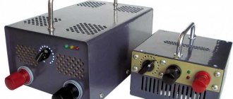
Welding machine "Terminator"
A welding transformer with a DC rectifier in a subsidiary farm is a very useful thing. However, if we take the above calculated transformer with a secondary stage power of 170 A, with a power consumption of almost 7 kW. At current electricity prices, one day of working with such a device will cost a considerable amount. At the same time, it is necessary to take into account another important thing, such as the pulsation of electricity in the general network, especially if it is a single single-phase network for the entire street (rural electrical wiring), and this is precisely where such products are most needed. This problem can be partly solved by the use of smoothing chokes, but if there is insufficient voltage in the network, voltage fluctuations can reach up to 50 V.
Even powerful chokes and network stabilizers cannot smooth out such surges. This negatively affects the operation of household appliances, such as refrigerators. And even then, showdowns with neighbors will definitely not be avoided.
With the development of modern technologies, the industry produces compact transformers. Since we already know the parameters of the required transformer, we will further consider devices for use in farmsteads within these limits. Well-demanded products from Moscow - terminator welding machine with rectifier
The Terminator welding transformer weighs 13 kg with almost professional characteristics: adjustable current spread from 30 to 170A, light weight and dimensions, low price (only 14 thousand rubles). It is precisely because of its light weight that the device has gained popularity. The device is in demand not only in home, but also in professional work, especially where welding equipment requires mobility - carrying from one place to another, for example, in the public sector; construction, repair of vehicle equipment, in general, anywhere where you need to frequently change your place of work.
The Terminator has a forced cooling system with fans that regulate the power of the air flow from temperature sensors. Such a cooling system makes it possible to use the device with a 70% NVF coefficient (duration of continuous switching on), which means that the device can operate for 10 minutes - 7 work, 3 rest.
If the windings overheat, the protection will disconnect the device from the load automatically. The windings in the transformer are made of 9% copper, which virtually eliminates losses due to internal resistance. Therefore, the device is very economical.
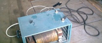
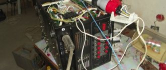
Welding machine design
Homemade welding device.
The rectifier of the device is a kind of shelf made of aluminum plates, which is tightened with pins. Each pair of diodes included in the rectifier design is clamped between plates 1 mm thick and measuring 44 x 42 mm.
The transistor, capacitors, thyristors, zener diodes, diodes and resistors are mounted on a fiberglass board.
The design of the welding unit includes the following elements:
- package switch, rated for 16 amperes or more;
- fan;
- diodes designed to operate at currents of 16 amperes or more;
- capacitors designed to operate at voltages of 400 volts or more;
- capacitors designed to operate at voltages of 1000 volts or more;
- thyristors KU221 A, installed on a radiator for cooling;
- KD13A or KD2997A diodes mounted on radiators with thyristors;
- resistors brand C5-16 or more powerful;
- screws, washers necessary for assembling the device;
- aluminum plates.
Read also: Comparator on lm358 circuit
For installation work you will need the following tools:
- soldering iron;
- pliers;
- screwdriver, knife, hacksaw;
- hammer;
- drill.
A welding unit made using these elements can be used for welding work in the household. It easily welds most metal products.
If you need to perform some simple welding work for domestic needs, it is not at all necessary to purchase an expensive factory unit. After all, if you know some subtleties, you can easily assemble a welding machine with your own hands, which will be discussed below.
Why remake the device?
Now you know that the question “So which current is better: alternating or constant?” has no answer. Devices on a break and devices on a permanent basis are two different phenomena with their own advantages and disadvantages. And ideally, it is better to have in your arsenal universal equipment that can cook with both direct and alternating current.
There are such devices on sale, but they are incomparably expensive. If you are a professional, then it makes sense to buy such a device. But if you are an amateur and cook a couple of times a year at your dacha or in the garage, then it is better to purchase a transformer device and modify it a little. A transformer operating on alternating current can be equipped with the ability to switch to direct current. This way you will get an inexpensive universal device, which will also be powerful and reliable.
Purpose
The welding rectifier is a device designed for steel and metal structures; an energy source for the welding arc, using semiconductor elements that converts the alternating current of the network into a direct welding current that does not change its direction and magnitude.
Welding rectifier Brima VDM 1203 (380 V). Photo Welding Technologies