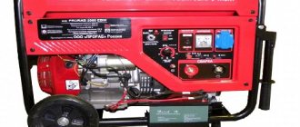
Resistance welding has long been used in all industries. This technology is no less popular among home craftsmen. It is quite difficult to assemble a spot welding machine with your own hands, but this approach helps reduce the cost of purchasing equipment.
Where is resistance spot welding used?
The technology involves connecting workpieces or welding individual parts to metal structures without creating an electric arc.
The method is applied under the following conditions:
- At manufacturing plants. Spot welding is used in the manufacture and repair of cars, aircraft, and complex technical equipment. The method helps to create strong, durable connections that have no signs of deformation or other defects.
- At home. A self-made machine is suitable for performing simple welding operations. It will help you weld elements of a fence or pipeline, or repair a car or motorcycle.
Process technology
To heat the parts to the required temperature, a short-term pulse of high-power electric current is applied to them. As a rule, the pulse lasts from 0.01 to 0.1 seconds (the time is selected based on the characteristics of the metal from which the parts are made).
When pulsed, the metal melts and a common liquid core forms between the parts; until it hardens, the welded surfaces must be held under pressure. Due to this, as it cools, the molten core crystallizes. A drawing illustrating the welding process is shown below.
Spot welding process illustration
Designations:
- A – electrodes;
- B – parts to be welded;
- C – welding core.
Pressure on the parts is necessary so that, when pulsed, a sealing belt is formed along the perimeter of the molten metal core, preventing the melt from flowing outside the zone where welding occurs.
To provide better conditions for crystallization of the melt, the pressure on the parts is gradually removed. If it is necessary to “forge” the welding site in order to eliminate inhomogeneities inside the seam, increase the pressure (do this at the final stage).
Please note that to ensure a reliable connection, as well as the quality of the seam, it is first necessary to treat the surfaces of the parts in the places where welding will take place. This is done to remove oxide film or corrosion.
When it is necessary to ensure reliable connection of parts with a thickness of 1 to 1.5 mm, capacitor welding is used. The principle of its operation is as follows:
- the capacitor block is charged with a small electric current;
- the capacitors are discharged through the parts being connected (the pulse strength is sufficient to ensure the required welding mode).
This type of welding is used in those areas of industry where it is necessary to connect miniature and subminiature components (radio engineering, electronics, etc.).
Speaking about spot welding technology, it should be noted that it can be used to connect dissimilar metals together.
Device design and necessary parts
Any contact type welding unit consists of 2 units:
- power supply (transformer);
- clamping pliers.
To obtain a powerful electrical discharge at a minimum voltage, an induction transformer is used.
The correct ratio of windings allows you to generate a current that is strong enough to melt the metal. The design of the pliers includes graphite or copper contacts installed on different levers that fix the mechanism.
The following types of clamps exist:
- Mechanical. Includes a powerful spring and lever. The welder's muscle force is used to compress metals. Clamps of this type are installed in household devices used for simple operations.
- Pneumatic. Installed in portable hand-held devices. Adjustable by changing the pressure in the air channel. The disadvantage is considered to be low productivity and the inability to adjust operating parameters during welding.
- Hydraulic. The clamps also have a low operating speed, but their range of settings is wider than the previous type.
- Electromagnetic. They are distinguished by the highest productivity and are installed in both manual and stationary units. Electromagnetic clamps allow you to adjust the compression force of parts during welding. This reduces the likelihood of lack of fusion and metal leaks.
Sometimes the design is complicated by adding liquid cooling systems, control of current parameters, and automatic movement of electrodes.
When assembling a homemade spot welding machine, the master will need the following parts and materials:
- a modified transformer from an old microwave oven or car battery;
- thick copper wire or cable harness of small cross-section;
- levers used to assemble clamps;
- base for installing unit blocks;
- clamps;
- wires;
- insulating materials;
- copper electrodes necessary for welding;
- control key.
We recommend reading Description of resistance spot welding technology
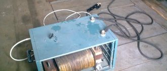
Battery device
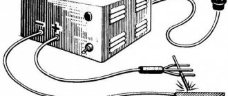
A do-it-yourself mini-spot welding device is made using a car battery. Its power is enough to weld a contact to another one that requires restoration.
Two brass or bronze rods are attached to a block with a copper alloy terminal block; they are insulated in the area of contact with the hand. It must be taken into account that during welding the rods will become very hot; the insulator-connector should not melt.
The disadvantage of this device is the lack of a switch and high battery power. You must work with the device carefully so that there are no burns in the contact area.
How to choose an air conditioner for your home or apartmentDo-it-yourself bait - composition, application features and storage methods (115 photos and videos)
DIY sliding gates - how to build simple and automatic gates. Schemes, drawings and review of the best ideas (90 photos)
General operating principles
The algorithm for assembling the welding unit includes the following steps:
- Removing the transformer. The part is taken from an old microwave oven. It is not completely needed; to manufacture the device, a primary winding and a magnetic circuit will be required. The remaining parts are carefully removed as unnecessary.
- Formation of a new secondary winding. To do this, use a copper cable with a cross-section of at least 100 mm². Durable rubber insulation is replaced with textile insulation. To create a powerful welding machine, 2 transformers with a common winding are used.
- Installation of a control unit that ensures uninterrupted flow of the contact welding process.
- Manufacturing and connection of electrodes, the type and diameter of which are selected taking into account the properties of the metals being welded.
- Housing assembly. The main units of the device must be reliably protected from external influences. At this stage, you can use the housing from an old microwave oven or assemble the structure yourself from sheets of metal.
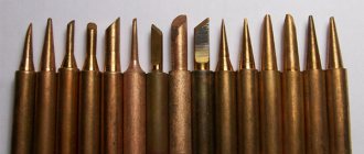
How to make electrodes
When manufacturing these elements, the following points are taken into account:
- The diameter of the electrode must correspond to the cross-section of the wire to which it is connected. Copper rods can be used as rods. Electrodes for low-power welding units are made from soldering iron tips.
- During the welding process, the electrodes wear out quickly. To restore their operating parameters, the ends are sharpened. Over time, the electrodes are replaced with new ones.
- The wire for connecting the welding rod should be short. Otherwise, part of the device's power will be lost. The current strength also decreases if there are a large number of connections in the electrode-transformer circuit.
- It is recommended to solder copper tips onto the wires to which the rods are connected. This increases the efficiency of the equipment. Since the electrodes are removable, the connection points with the tips are not soldered.
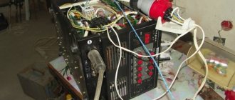
Pulse Welding Assembly
Converter
Let's start by assembling the converter. Which is also called the power part of the welding machine. Below you can see a detailed assembly diagram.
We have also provided several tables with specifications of the components used.
Control circuit
Below is a clear and working control diagram, and a small part of the device’s startup diagram is also visible.
As when assembling the converter, we have provided several tables with the specifications of the components used.
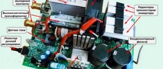
Pay
Below you can see a schematic image of the printed circuit board.
And here is the layout of all the elements on the board.
Please note that the “soft start” is located on the control board.
Complete device
Below you can see the assembled device. This is its simplest form. What is missing is a housing with fans, a control board (it needs to be attached to the housing itself), a connector for welding current, as well as a surge protector and a circuit breaker (also attached to the housing).
Assembling a device from a microwave oven
The device manufactured in this way allows welding with alternating current with unregulated force.
List of required tools
To create a homemade device from a microwave oven, you will need the following equipment:
- Screwdriver Set;
- sandpaper;
- copper rods;
- hammer;
- chisel;
- knife.
Conversion of microwave parts
After removing the transformer from the furnace, perform the following steps:
- Remove the secondary winding using a hacksaw or chisel. Dismantling is carried out carefully, trying not to damage the underlying layer. It is advisable to fill the space between the windings with corrugated cardboard.
- Remove the metal shunts that limit the current.
- A secondary winding is formed. At this stage, you will need a KG 1x35 wire. It can withstand prolonged exposure to high voltage and current up to 1200 A. The outer rubber insulation is removed from the cable.
- The core is covered with tape, which facilitates the sliding of the wire during winding. The cable is laid in 3 tight turns. For winding, the use of stranded soft wire is allowed. The total diameter of the cores must be at least 1 cm.
We recommend reading: How to make a welding machine from a microwave
After the alteration, the transformer must have an open circuit voltage of no more than 3V and a current of at least 800 A.
Homemade device diagram
Creating an electrical circuit for a welding machine is not difficult. The electrode is connected with a soft cable to the secondary winding of the transformer. The circuit includes thyristors and rectifier bridges. One end of the pressure gun is connected to the secondary winding, the other is securely fixed to the device.
The operating principle of the electrical circuit of the unit is as follows:
- Single-phase or three-phase current is supplied to the clamping mechanism.
- When the button on the gun handle is pressed, the thyristor opens.
- The capacitor is charged from the transformer. The thyristor closes, the clamping mechanism is activated. The latter operates until the capacitor discharges. Pressing the button again will generate a new impulse. The time for maintaining the charge of the capacitor is set by a variable resistor.
Assembling the device
To create the working part of the device, perform the following steps:
- Assemble the base from the bottom of the microwave oven body. One end of a metal profile or wooden beam is fixed to it. To do this, use self-tapping screws to ensure a strong fixation. A welding electrode with a cable connected to a transformer is connected to the second edge of the profile. The wire is wound around the rod, which prevents damage.
- A movable part of the apparatus is installed, which looks like a lever. A long nail is used as an axis. The side posts, created from profiles or bars, are fastened with self-tapping screws. There should be no distance between them and the base of the lever. Otherwise, the accuracy of the device’s impact is reduced.
Performance test
After all installation and assembly work, the device is checked in the following ways:
- The main operating parameters of the unit are measured. An oscilloscope is used for this. The current pulse strength should be about 800 A.
- The assembled device is used in practice. To do this, create a test seam. After completion of work, measure the temperature of the transformer. If it is too high, the circuit is not assembled correctly. When the indicator is within the normal range, 2 more test stitches are made.
Device designs
It was said earlier that do-it-yourself spot welding can be assembled by any craftsman. At the moment, there are a large number of examples on the Internet dedicated to the manufacture of such equipment.
Do-it-yourself welding will allow you to solve a large number of problems related to the repair and manufacture of various products and mechanisms. This device will be indispensable in almost any workshop or garage.
The most important fact is this: making a unit with your own hands from a welding device is not difficult. As a result, with this device, creating high-quality and reliable connections of various metal products will become commonplace.
Depending on the characteristics of the workpieces being welded, such as their size, thermal conductivity, etc., the welding process should be carried out with the following parameters:
- the power circuit voltage ranges from one to ten volts;
- the process time should last from 0.01 to several seconds;
- the welding pulse current exceeds a thousand amperes;
- the melting zone of the surface of the parts is minimal;
- the pressure applied to the welding site must reach tens and sometimes hundreds of kilograms.
It is enough to comply with all the above parameters, and then the quality of the connection will not raise any doubts. You can do resistance welding with your own hands in accordance with one of the diagrams presented on the Internet.
Electrical circuit of the welding machine.
The most common option is microwave welding. This is due to the fact that getting this device in our time is not difficult. The assembly process itself is quite simple and only requires careful adherence to the instructions.
Also common are devices based on laboratory autotransformers, inverters, etc.
Let's look at one of the options on how to make spot welding.
For these purposes we will need:
- variable resistance element, nominal 100 Ohm;
- a capacitor with a capacity of one thousand microfarads, designed for a voltage of at least 25 V;
- thyristor;
- diodes;
- five amp fuse.
Blueprints
Do-it-yourself contact-type welding can only be done if the drawing is chosen correctly. Here preference should be given to the simplest schemes with the least number of components and parts.
It is worth keeping in mind: DIY welding does not have too much power. However, it is quite sufficient to perform almost all everyday tasks that arise when working in the country, in a workshop or in a garage.
Before you understand the assembly of such a device, you should remember the school physics course, namely the Joule-Lenz law. The essence of the law is as follows: current passing through a conductor creates thermal energy. Its value is proportional to resistance, time and the square of the current.
The conclusion from the above law is as follows: if the current is large, for example, on the order of a thousand amperes, then in the case of poor contact and the use of thin wires, the energy consumption will become too large and will be several thousand times higher than the consumption corresponding to a current of ten amperes.
In this regard, the quality of the assembled electrical circuit is very important.
Required Parts
To assemble a spot welding machine with your own hands, you should make sure that you have certain parts. Such a device, made at home, can have any shape and dimensions. There are two main types of implementation of the unit: in the form of a portable structure or in the form of a large-sized stationary version.
The most practical is tabletop resistance spot welding. It will cope perfectly with the simplest tasks of joining thin sheet metal. It can also be easily transported or simply moved around the workshop.
Processes during spot welding.
So, we will need:
- a transformer that you can make yourself from microwave spare parts; an LATr or a transformer from a TV is also an excellent option;
- cable with a cross-section of ten millimeters;
- copper electrodes;
- timer;
- tips;
- bolts;
- various available materials for making the body, mass, etc.
Spot welding with a spotter is done both using a ready-made diagram and on the basis of drawings developed independently. All necessary parts are purchased in the appropriate stores or taken from “donor equipment”.
When manufacturing this device, it is important to select the right components based on the parameters and characteristics of the transformer.
Only use wires with the correct size for the current flowing through them. When contacts are poorly made, they will experience large energy losses. As a result, the connections will spark and heat up, and the welding process will simply become impossible.
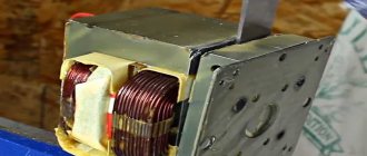
Transformer assembly process
Many people are interested in the question: how to properly weld from a microwave?
So, to assemble a homemade spot welding machine, you need a transformer. This element is the heart of the device and the parameters of the device as a whole will depend on its characteristics. Taking a transformer for spot welding, as noted above, follows from the microwave.
Any microwave oven is equipped with a magnetron, which provides the necessary electromagnetic radiation necessary for heating food. This node requires a fairly high voltage.
The microwave transformer connected to the magnetron is a step-up transformer. Its primary winding has fewer turns than its secondary winding. Thanks to this, a voltage of up to two kilovolts is formed on it. Due to the doubler, this value is then multiplied by 2 times.
It is necessary to carefully and carefully remove the transformer from the microwave oven. The microwave should be disassembled by removing the base and removing the fasteners. In the case of making spot welding from a transformer, only two of its components will be needed from the furnace.
Structural elements of a welded joint.
The first is the primary winding, the mains voltage is supplied to it, the second is the magnetic circuit. It needs to be improved so that it can provide the necessary parameters of the transformer.
The secondary winding is not needed, so it is dismantled using a hammer, chisel or chisel. The main thing is not to damage the primary winding. If during dismantling you find shunts designed to limit the current, they should be removed.
In a microwave oven, two options for implementing a magnetic core are possible: adhesive and welded. In the first case, it is best to remove the winding using a hacksaw or chisel. But in the second case it needs to be drilled out. Such operations should be performed with the utmost care to avoid damaging the magnetic circuit.
After the transformer is removed from the microwave, you need to wind the secondary winding. For these purposes, a wire with a diameter of at least one centimeter is perfect. If the farm does not have one, it will have to be purchased.
It is not necessary to buy a solid single-core wire; you can get by with a bundle of several individual wires with a total diameter corresponding to the required one. Once the secondary winding is complete, the resulting upgraded transformer will provide up to a thousand amps of current.
This value is quite enough for a do-it-yourself device to allow you to easily connect small parts, repair body work, and much more.
If it is necessary to manufacture a more powerful device, the parameters of one transformer may not be enough. In this case, you can use two such elements.
In this type of welding, it is necessary to obtain 2 V at the output, which will provide a current of more than eight hundred amperes. This result can be achieved by winding two or three turns on the core of the secondary winding.
Forming the required number of turns can cause certain difficulties if the insulation on the wire is too thick. This problem can be solved quite simply: the insulation is removed from the wire and another one is made instead using fabric insulating tape.
The shortest length of wire used in the secondary winding is important. This is necessary to minimize electrical resistance.
If it is necessary to weld metal workpieces with a thickness of more than five millimeters, you will need a device with high power. In the manufacture of such a device, two transformers should be used, connected into one electrical circuit.
In this matter, it is important to follow all the rules of such a connection. An error in connection and incorrect assembly will lead not only to the inoperability of the device, but also to a short circuit.
After connecting the terminals of the same name, the current generated by the windings is measured. Typically, such devices are capable of providing a current of two thousand amperes. If this value is exceeded, then malfunctions may occur in the electrical circuit not only of your home, but also of your neighbors.
So, what results can be achieved if two transformers of equal power and parameters are connected to each other?
Let's say there are two identical devices with a power of half a kilowatt, the input voltage corresponds to the network value and is 220 V, and at the output the transformer produces two volts and provides a current of 250 amperes.
Scheme of capacitor spot welding.
If two such devices are connected in series with each other, then they can provide a rated current of five hundred amperes. However, during its formation, significant losses will occur due to the significant electrical resistance of the circuit.
Homemade pliers for resistance welding are subsequently connected to both ends of the winding.
If there are 2 transformers with sufficiently high power, but their output voltage is still not enough, then their secondary windings are connected in series to each other.
In this case, the essential point is the number of turns wound on both windings. This method turns out to be especially useful when it is simply impossible to rewind the turns due to the insufficient size of the magnetic circuit.
When making such a connection, it is important to carefully monitor the coordinated direction of the turns on the windings connected to each other. Otherwise, the output voltage from the two windings will be in opposite phases. After summation it will be equal to zero.
If the transformer terminals are not marked, then you should determine which of them are of the same name and connect them to each other. This problem is solved as follows: the secondary and primary windings of the transformers are connected in series, voltage is applied to the input, and a voltmeter is connected to the output.
Depending on how the devices are connected, the voltmeter will either show some number or nothing. The first case is realized when there are different terminals in the connection circuit.
This connection is incorrect. In such a case, the following processes will occur in the windings: the voltage arriving at the input of the device will decrease by half on each of the primary windings, since they have the same transformation ratio.
As a result, a voltmeter installed at the output will show twice the input voltage.
In the second case, when the voltmeter shows 0, the following situation occurs: the voltages coming out of the windings of each transformer connected to the circuit are equal in magnitude. However, the signs of the stresses will be different, which means they compensate each other.
Electrodes
Welding spotter is equipped with copper tongs. They will subsequently be used in connecting metal workpieces to each other.
Electrodes for spot welding can have several design options. They are installed directly into the body of the device itself, or a remote device in the form of scissors is implemented.
A simpler option in the case of self-manufacturing of a resistance welding machine is electrodes built into the body. The disadvantage of the design is the insignificant clamping pressure corresponding to the force of the welder if the distance from the device to the end of the pliers is not increased.
Remote electrodes are easier to use. They can be used even at some distance from the spot welding device. The pressure generated by this design depends on the length of the lever between the movable joint and the ends of the pliers.
It is very important to insulate the moving connection well. Textolite bushings and washers are used for these purposes.
The issue related to the length of the lever should be thought through in advance, even at the stage of manufacturing the pliers. Welding machines, as noted above, require significant compressive forces to be applied to metal workpieces during welding.
Spot welding machine design.
Another important point is the length of the handles. It determines the maximum distance from the edge of the parts being welded to the joint.
Typically, the most common material from which electrodes are made is copper, but beryllium bronze can also be used. Soldering iron tips are perfect for a simple and ready-made option. The important thing is the diameter of the clamps, which is no less than the diameter of the wires connected to them.
At the same time, the tips of the electrodes are made small, almost sharp. This will allow you to obtain kernels of sufficiently high quality.
It is also worth not forgetting about degradation processes. Over time, the electrodes can wear out. In this case, they will sometimes have to be sharpened. Nevertheless, sooner or later the electrodes will have to be replaced.
If you use copper rods as the electrode material, then replacing them will not cause any particular difficulties. On the other hand, a better welding result is achieved when using tips from professional soldering irons, but their price is higher than that of simple rods.
Which design option to choose is up to everyone to decide for themselves. It all depends on what tasks are to be solved with the help of this device, as well as on the financial capabilities of the person.
Do not forget that in wires, in any case, there will be losses of electricity due to heating, because any conductor has resistance.
The principle of operation of the welding device was already mentioned above and the Joule-Lenz law was discussed. It is also applicable in the case of simple conductors, since their resistance is not zero. This means that when current flows through the copper wires, heating will occur.
From the above it follows: the length of the wires connecting the electrodes and the device must be minimal. Only in this case will it be possible to realize the full potential of the unit.
Control
To make a welding machine an easy-to-use device, you need to take care of the controls. Its implementation is not too difficult. For these purposes, you will need only two main elements: a lever and a switch.
As you can see, the control circuit in ordinary homemade spot welding does not require the presence of any complex parts or their purchase. After all, with a high degree of probability, they are already in the household of almost any master.
The role of the lever is to ensure reliable contact between the parts being welded. It is possible to increase the compressive force of this unit through the use of screw elements. Of course, this part must be highly reliable, otherwise homemade spot welding will not last long.
In large and critical industries, the compression force between two connected parts reaches thousands of kilograms. Spot welding at home, intended for occasional work, does not require industrial loads.
Usually in everyday life a pressure of thirty kilograms is sufficient. The welder can provide it independently, but increasing the length of the lever will significantly simplify this task.
Drawing of spot welding of metal products.
More specifically, a handle length of 60 centimeters is quite enough. Such a lever is capable of increasing the force applied to its shoulder by approximately ten times. As a result, to achieve a force of 30 kilograms, it is enough to press on the shoulder with a force equivalent to 3 kg.
The resistance welding spotter switch is connected directly to the transformer. The connection must be made to the primary winding, where the current strength is negligible.
If you connect it to the secondary winding, it will not only increase losses by creating additional resistance, but will also be tightly welded to the leads of the welding transformer.
The design with the switch located directly on the handle of the lever is very convenient. This option allows you to leave one hand free, which will simplify the task of supporting the parts being welded.
It is also worth considering the heating to which a homemade spotter made from a welding transformer is exposed. In this regard, it is necessary to provide a cooling system. A simple fan is suitable for its implementation.
In addition, short breaks should be taken so that the resistance welding machine does not overheat. You should monitor the duration of welding of products visually, or use a controller for this purpose.
In case of short-term operations, such as welding wire, there is no need to worry about heating. But in longer processes, this point is extremely important and should not be forgotten.
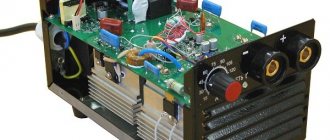
Contactor from a welding transformer
Such equipment can be turned into a full-fledged resistance welding tool. The only drawback is the inability to control the current strength.
Drawing development
The correct choice of circuit helps to produce a working welding machine. Preference is given to simple drawings that include a minimum number of parts and blocks. Such options do not allow you to create an overly powerful device, but the device is sufficient to perform minor repairs on a car, garden equipment, and fences.
We recommend reading Description of resistance spot welding technology
List of parts and consumables
To convert a welding transformer into resistance welding equipment, you will need the following elements and materials:
- a transformer that converts electrical energy;
- thick cable;
- copper electrodes;
- bolts;
- tips;
- breaker;
- wooden blocks, plywood to create the body.
The process of creating a device
The homemade device is assembled as follows:
- The welding transformer is installed in a housing made of metal sheets. The electrical board is assembled on a textolite sheet more than 1 cm thick. The part is fixed in the body of the welding machine.
- A welding wire is bolted to the busbar and secondary winding. The remaining end of the cable is connected to the electrode.
- The power wire is connected to the contact block located on the electrical board.
Spot Welding Operation
A master using a contact transformer apparatus must stand on a rubber mat and use protective gloves and goggles. The grounding cable is connected to the part to which another workpiece will be welded. After this, press the power key, compare the elements to be connected, and clamp with the electrode of the welding gun.
5 seconds after the start of the impact, the rod is transferred to the next point.
DIY resistance welding pliers
To make such a device yourself, follow these steps:
- Form the basis. For this purpose, available materials are used - steel sheets up to 5 mm thick. Strips 2 cm wide are cut from them. The length depends on the design of the welding tongs. The strips can be replaced with metal rods. The ends of the two blanks are bent in the form of tongs.
- Place the parts on top of each other and join them together. A hole is drilled in the central part where the adjusting screw will be located. A dielectric layer is placed between the plates.
- A hole is drilled at one end of the rod or strip to secure the copper cable. The same actions are performed for the second workpiece. The holes should be opposite each other.
- The metal elements of the pliers are covered with a rubber pad and electrical tape. The materials will protect the welder from electric shock during work.
- Install the spring between the handles of the pliers. The part is necessary for fixing the elements to be welded.
Using spot welding on lithium batteries
Using a battery to weld a nickel plate to the battery is the easiest way. To assemble the mini-unit you will need a battery, a charging cable, a piece of single-core wire, and electrical tape. 2 electrodes are created from the core, the ends of which are stripped and secured. The distance between elements should be 3 mm.
A charging cable connected to the terminals of the lithium-ion battery is connected to the other ends of the electrodes. Place the nickel plate on the battery and press the energized electrodes against it. As a result of a short circuit, the metal melts.