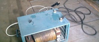
We are making a simple 12-volt rectifier to charge car batteries. It all started when they brought me a non-working 22V and 110V power supply to my work. I decided to use it to make a battery charger for my car. The battery is naturally 12V. First, I disassembled the power supply and looked at what was inside. As it turned out, there was nothing except the transformer. The power supply did not work due to the fact that one wire for supplying electricity simply somehow fell off. Still, the device is from Soviet times and has become worn out over time. I decided to throw out the case and all the wires and make it all over again.
I took the transformer out of the device. There were two secondary windings. One was 22V, the second was 110V. But this voltage was not suitable for charging the battery.
I disassembled the transformer, took out all the plates, unwinded the secondary winding at 22 V. I wound a new winding at 12 V with a new, thicker wire. It contained half as many turns as the previous one, but since the cross-section of the wire was increased, it filled the window completely. Everything was carefully assembled and checked. The output turned out to be 13.4V. This was great for the battery.
12 volt rectifier circuit
Next, I decided not to complicate matters with all sorts of clever chargers on microcircuits, but to assemble a simple and reliable rectifier using diodes. I took D242 diodes. They are very reliable, but they get a little hot, so they should be installed on radiators.
Soldered according to the standard diode bridge circuit. I connected it - everything worked perfectly, the output was now 13.7V. As it should be, the voltage increased slightly after rectification. But it's okay. For batteries, you need not strictly 12, but approximately 14 volts for a normal charge.
Everything was neatly placed in the new case. I made an output to the rectifier. I connect it and use it with pleasure. I also made an indicator of the presence of electricity - I simply connected a regular LED to a 220V network through a resistor. The result is a simple and reliable rectifier for a 12 volt charger.
Source: serp1.ru
How to make a simple 12 volt power supply from a transformer, rectifier, capacitor.
Topic: how to solder a 12 volt power supply with your own hands (diagram).
If you need a constant power source with a voltage of 12 volts, but you don’t have it at hand, then you can buy it. If you take a cheap power supply, then its quality will leave much to be desired. Usually such inexpensive power supplies are good only in appearance. When you open them, it turns out that its current characteristics (indicated on the case) are too high. In reality, it is not able to fully provide the power that is declared by the manufacturer (as a rule). You can buy a more expensive 12-volt power supply, but assembling it yourself piece by piece will be much cheaper, and the quality is no worse.
So, how to make a good and simple 12-volt power supply with your own hands, what do we need for this? You need a step-down power transformer, a rectifying diode bridge and an electrolyte filter capacitor. The transformer will lower the mains voltage (220 V) to the required level, namely 10 volts. Why up to 10, and not 12. Because there is such an effect - the alternating voltage after the diode bridge (which has a capacitor of sufficient capacity) will become about 18 percent higher than without a capacitor. This should be taken into account when assembling any power supply.
What is good about the device and what hinders it?
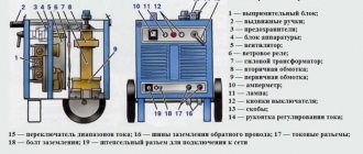
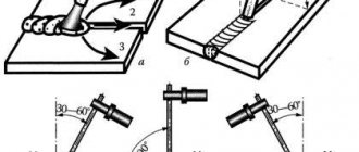
How to convert an AC welding machine into a DC welding machine - the necessary semiconductor circuit with a rectifier device will answer this question for the master:
- The three-phase system has the best performance; it allows you to use network power up to 380 V.
- Such equipment is used where a large continuous process is needed in order to weld large steel parts without interruption during this time period. With the help of these powerful devices you can produce gates, containers, and any utility metal structures.
- Such a tool will be useful mainly not in a private household, but for small businesses and the sale of manufactured products. This is because these are bulky and heavy structures, unlike devices with fewer phases, they require additional installations to move the device.
In such a system, the transformer is capable of reducing weight, but you need to be able to wind its core yourself or buy a ready-made one with the necessary parameters.
How to make a 12 volt voltage stabilizer with your own hands
A 12 volt voltage stabilizer is often used in a car's electrical circuit. The need to install it is explained by the fact that car power supplies (battery and generator) of various 12-volt electrical appliances produce direct current with a voltage of 12.5 to 14 V. Such large fluctuations can lead to damage and failure of sensitive and expensive LED tapes, fog lights, radios. Also, in addition to the electrical systems of cars, such devices are used in 12-volt power supplies that are capable of reducing and converting the alternating current of the household electrical network into a direct current more suitable for a number of devices.
Homemade welding rectifier for single-phase network
Let's remember the school physics course and talk about theory. Alternating current is a sine wave or wave that produces oscillations at a frequency of 50 Hz. This means that in 1 second, electricity flows 25 times in one direction and 25 times in the opposite direction. The welding process requires electricity to flow in only one direction.
If the circuit of the secondary winding of the transformer is supplemented with a semiconductor element, for example a simple diode, then it will pass electricity only in one direction, which means we will get a direct current. However, it will be pulsating, with a frequency of 25 Hz, i.e. after each “wave” there will be a pause of similar duration, without current, and this does not suit us.
If the diode is placed in reverse, then it will pass the flow of electrons in the other direction, the so-called reverse half-wave. By placing two diodes towards each other, between them we get a current, which is waves that increase from zero to the maximum voltage value for which the secondary winding of the transformer is designed and decrease to zero, after reaching which a new wave will begin.
Device selection
When choosing a stabilizer, take into account the following characteristics:
- Dimensions. The selected stabilizer must be compactly placed in its planned installation location with normal access.
- View. Of the commercially available devices, the most reliable, compact and inexpensive are stabilizers based on small microcircuits.
- Possibility of self-repair. Since even the most reliable devices fail, it is necessary to give preference to repairable stabilizers, radio components for which are commercially available in sufficient quantities and at an affordable price.
- Reliability. The selected stabilizer must provide a constant voltage value without significant deviations from the range declared by their manufacturer.
- Price. For the electrical system of a car, it is enough to purchase a device costing up to 200 rubles.
Also, when choosing a stabilizer, it is necessary to take into account customer reviews, which can be found on specialized forums and websites.
Types of 12V stabilizers
Depending on the design and method of maintaining a 12-volt voltage, there are two types of stabilizers:
- Pulse stabilizers, consisting of an integrator (battery, high-capacity electrolytic capacitor) and a switch (transistor). Maintaining the voltage in a given range of values occurs due to the cyclic process of accumulation and rapid release of charge by the integrator when the key is open. According to their design features and control method, such stabilizers are divided into key devices with a Schmitt trigger, equalizers with pulse width and pulse frequency modulation.
- Linear - voltage-stabilizing devices in which zener diodes or special microcircuits connected in series are used as a regulating device.
The most common and popular among car enthusiasts are linear devices, characterized by ease of self-assembly, reliability and durability. The pulse type is used much less frequently due to the high cost of parts and the difficulties of independent production and repair.
Classic model
Classic stabilizers are a large class of devices assembled based on semiconductor parts such as bipolar transistors and zener diodes. Among them, the main function of maintaining the voltage at 12 V is performed by zener diodes - a type of diodes connected in reverse polarity (the plus of the power supply is connected to the cathode of such a semiconductor device, and the minus to the anode), operating in breakdown mode. The essence of how these semiconductor parts work is as follows:
- When the voltage of the power source connected to the zener diode is less than 12 V, it is in the closed position and does not participate in adjusting this characteristic of the electric current.
- When the threshold of 12 Volts is exceeded, the zener diode “opens” and maintains this value in the range specified by its characteristics.
If the voltage supplied to the zener diode exceeds that stated as the maximum by the manufacturer, the device very quickly fails due to the effect of thermal runaway.
In order for any model of zener diode to serve as long as possible, it is recommended to specify, according to its specification, the voltage range and current strength in which it should be operated.
Depending on the connection, there are two versions of the classic stabilizer: linear - the adjusting elements are connected in series with the load; parallel – voltage stabilizing devices are located parallel to the powered devices.
Inverter welding rectifier: let's look at what's what
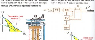
The operating diagram of the inverter device is slightly different than the classic one. Instead of a step-down transformer, an electronic filter is installed at its input, which converts the frequency of the incoming electric current from 50 Hz to several tens of kHz. Afterwards a step-down transformer is installed, and only then a rectifier bridge. The advantages of such welding machines are their low weight compared to conventional ones. This is achieved due to the fact that the magnetic core of the high-frequency transformer has smaller weight and dimensions.
Rectifiers for inverter welding machines are built on the basis of thyristors, with a pulse-phase control system. Next, as expected, a capacitor is connected to the welding circuit, parallel to the load, and a rheostat and a choke are connected in front of the welding electrode. The disadvantage of the rectifiers under consideration is the amount of electronics; it is almost impossible to assemble it yourself, as well as to repair it. Single-station welding rectifiers with good rectified current performance can be assembled at home if all the necessary components are available, and this is a worthy alternative to buying a new rectifier.
- Author: Mikhail Malofeev
Rate this article:
- 5
- 4
- 3
- 2
- 1
(0 votes, average: 0 out of 5)
Share with your friends!
Integral stabilizer
The devices are assembled using small-sized microcircuits capable of operating at an input voltage of up to 26-30 V, delivering a constant 12-volt current of up to 1 Ampere. A special feature of these radio components is the presence of 3 legs - “input”, “output” and “adjustment”. The latter is used to connect an adjustment resistor, which is used to adjust the microcircuit and prevent it from overloading.
More convenient and reliable equalizers assembled on the basis of stabilizing microcircuits are gradually replacing analogues assembled on discrete elements.
How to make a 12V stabilizer
Simple, but at the same time quite effective, reliable and durable stabilizing devices can be made independently, using simple zener diodes and special small microcircuits such as LM317, LD1084, L7812, KREN (KR142EN8B).
Stabilizer on LM317
The assembly process of such a voltage-stabilizing device consists of the following steps:
- A 130-ohm resistance is soldered to the middle output contact of the microcircuit.
- A conductor is soldered to the input right contact, supplying an unstabilized voltage from the power source.
- The left adjustment contact is soldered to the second leg of the resistor installed at the output of the microcircuit.
The soldering process of such a stabilizer takes no more than 10 minutes and, taking into account the inexpensive microcircuit, does not require large investments. Using a similar device, LED lights and strips are powered.
Chip LD1084
The assembly of a device for stabilizing the voltage of an automobile on-board network using the LD1084 microcircuit is carried out as follows:
- A conductor with positive voltage from the diode bridge is soldered to the input contact of the microcircuit.
- The emitter of a bipolar transistor is soldered to the adjustment contact, the base of which, through two resistors with a nominal value of 1 kOhm, supplies the current of the low and high beam headlights.
- Two resistors are soldered to the output contact (one is a regular 120 Ohm, and the second is a trimmer, 4.7 kOhm) and a 10 µF electrolytic capacitor
To smooth out the current ripple, another electrolytic capacitor with a capacity of 10 μF is installed after the diode bridge.
Stabilizer on diodes and L7812 board
A simple integrated equalizer using a Schottky diode and two capacitors is assembled as follows:
- The following is soldered to the input contact of the microcircuit: a 1N4007 type diode, the anode of which is connected by wire to the plus of the power source, the positive plate of a powerful 16-volt electrolytic capacitor with a capacity of 330 μF.
- The load and the leg of the positive plate of a 16-volt 100 µF electrolytic capacitor are soldered to the right output contact.
- The negative coming from the battery and the wire from the negative plates of the capacitors are soldered to the middle adjusting contact.
From such a simple device you can power powerful LED strips and a radio tape recorder.
The simplest stabilizer is the KREN board
The 12-volt voltage stabilizer circuit based on the bank board (KR142EN8B) includes the following components:
- A 1N4007 type rectifying diode soldered to the input pin.
- Chip KR142EN8B or KIA7812A.
- Two wires soldered to the output and control pins of the microcircuit and connected to the load and minus of the power source.
The design on the KREN board is the simplest and fastest to assemble. At the same time, its effectiveness and scope of application are the same as those of other homemade analogues.
Output voltage stabilization
A stabilizer at the output of the power supply is not always needed. So, if you plan to use a power supply in conjunction with sound-reproducing equipment, then the output must have a stable voltage. And if the load is a heating element, the stabilizer is clearly unnecessary. To power an LED strip, you can do without the most complex power supply module, but on the other hand, a stable voltage ensures independence of the brightness of the glow during changes in the network and extends the life of the LED lamp.
If the decision to install a stabilizer has been made, then the easiest way is to assemble it on a specialized microcircuit LM7812 (KR142EN5A). The connection circuit is simple and does not require adjustment.
Stabilizer for 7812.
The input of such a stabilizer can be supplied with voltage from 15 to 35 volts. A capacitor C1 with a capacity of at least 0.33 μF must be installed at the input, and at least 0.1 μF at the output. The capacitor of the filter unit usually acts as C1 if the length of the connecting wires does not exceed 7 cm. If this length cannot be maintained, then the installation of a separate element will be required.
The 7812 chip has protection against overheating and short circuit. But it does not like reversing the polarity at the input and applying external voltage to the output - its life time in such situations is calculated in seconds.
Important! For load currents above 100 mA, installing an integrated stabilizer on the heat sink is mandatory!