Pulse welding - what is it? In essence, this is ordinary electric arc welding, during which additional short-term pulses are applied. Please do not confuse this type of welding with spot welding. Pulsed spot welding and pulsed arc welding are two radically different methods of joining metals.
But what if you want to try this method of joining metals in your practice, but do not want to spend a lot of money on buying a high-quality welding machine? There is a solution! You can make homemade pulse welding. Pulse welding can be assembled on your own in one and a half to two hours, and all components are inexpensive. In this article we will tell you in detail how to make pulse welding with your own hands and what is our experience in using a homemade welding machine.
DIY pulse welding
Pulse welding - what is it? In essence, this is ordinary electric arc welding, during which additional short-term pulses are applied. Please do not confuse this type of welding with spot welding. Pulsed spot welding and pulsed arc welding are two radically different methods of joining metals.
But what if you want to try this method of joining metals in your practice, but do not want to spend a lot of money on buying a high-quality welding machine? There is a solution! You can make homemade pulse welding. Pulse welding can be assembled on your own in one and a half to two hours, and all components are inexpensive. In this article we will tell you in detail how to make pulse welding with your own hands and what is our experience in using a homemade welding machine.
Sample devices
An example of equipment for jewelry spot welding is the unit (Germany) and Orion pulse150i (USA).
Both devices are equipped with binoculars, through which you can see the smallest details of the jewelry. To protect the eyes, the eyepieces are equipped with a shutter that closes during an arc discharge.
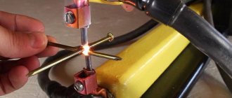
The work proceeds as follows. The jewelry is fixed in the place intended for this purpose, while a special clamp ensures its reliable contact with one pole of the device.
The jeweler touches the item with an electrode in the right place. At this moment, the storage capacitor is discharged, and the moving part of the electrode is automatically retracted, creating a spark gap in which an electric arc burns. At the same time, a portion of argon is supplied through a hole in the center of the electrode.
During the welding process, if necessary, filler wire can be used to fuse with the material of the product.
Pulse Welding Assembly
Converter
Let's start by assembling the converter. Which is also called the power part of the welding machine. Below you can see a detailed assembly diagram.
We have also provided several tables with specifications of the components used.
Control circuit
Below is a clear and working control diagram, and a small part of the device’s startup diagram is also visible.
As when assembling the converter, we have provided several tables with the specifications of the components used.
Pay
Below you can see a schematic image of the printed circuit board.
And here is the layout of all the elements on the board.
Please note that the “soft start” is located on the control board.
Complete device
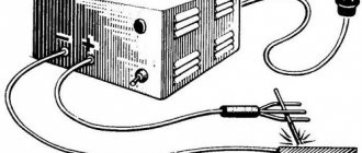
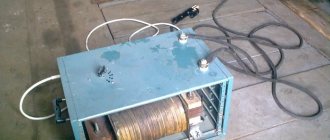
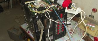
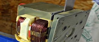
Below you can see the assembled device. This is its simplest form. What is missing is a housing with fans, a control board (it needs to be attached to the housing itself), a connector for welding current, as well as a surge protector and a circuit breaker (also attached to the housing).
Application experience
Our experience has shown that a device assembled according to these circuits works almost flawlessly. We were pleased with the functionality and quality of the resulting seams. Of course, with the help of such a unit you will not be able to perform professional welding work, but it is not necessary. This homemade welder is suitable for pulse welding of a fence or greenhouse. In a word, it will not let any home craftsman down, and its assembly will be very cheap.
The welder assembled according to these diagrams is designed to work on a 220V network. But in our memory there have been situations when the voltage was unstable, especially in the country. Nevertheless, the arc burned stably and was ignited quite simply. Yes, this is not professional micropulse welding, but still. By the way, we recommend using only consumable electrodes when working with such a homemade device. Welding with a consumable electrode is much more effective and stabilizes the arc quite well.
Naturally, we needed to spend our own time and effort to assemble it. But the final cost of a homemade pulse welding machine turned out to be several times lower than that of budget models from the store. At the same time, the homemade device copes with its functions perfectly.
Preparing parts
Before starting capacitor welding, it is necessary to prepare the parts to be joined. Rust, scale and other contaminants are removed from them.
The workpieces are properly aligned and then placed between the lower fixed electrode and the upper movable one. They are then strongly compressed by the electrodes. By pressing the start button, an electrical discharge is applied.
Metal welding occurs at the point where the electrodes touch. It is necessary to release the electrodes after some time necessary for cooling and crystallization of the welding site under pressure.
After this, the part moves, during which time the device has time to charge, and the welding process is repeated. The size of the welding site should be 2-3 times larger than the smallest thickness of the workpieces being joined.
When you need to weld a sheet up to 0.5 mm thick to other parts, regardless of their thickness, you can use a simplified welding method. One electrode is attached using a clamp to the thick part being welded in any convenient place.
In the place where a thin part needs to be welded, it is pressed manually with a second electrode. You can use car clamps. Then welding is done. As you can see, the process is not too complicated and can be done at home.
Advantages of a homemade device
In addition to the price, a homemade pulse welding machine has many other advantages over models sold in stores. The first advantage is low current consumption. If you plug an ordinary device from a store into a household outlet at your dacha and weld a gate, for example, you will soon receive electricity bills and be unpleasantly surprised. In addition, connecting such a device to a household outlet is simply dangerous; the machines may not withstand such power.
Don’t forget about the dimensions of purchased devices. It is simply impossible to calmly carry them in your hands from place to place. In factories, welders simply use very long wires so as not to move such a device around the workshop. However, the price for such wires is very high, and we don't think you'll want to spend an extra $100 on cables. But the homemade device weighs little and can be easily moved.
Also, purchased devices have their own production capabilities, and they rarely exceed 80%. And often they are at around 50%. This means that such a device simply cannot reveal its full potential. This happens because a large and technically complex welder gets very hot and takes a long time to cool down. For this reason, you will also not be able to cook for more than 2-3 minutes at a time.
A homemade welder assembled according to our diagrams does not have such disadvantages. There are no reactive currents in it, so almost all electrical energy is used. You can easily connect such a welder to a home outlet and not worry about electricity bills and possible operating time. After all, the power of our homemade device is only slightly greater than the power of a regular iron.
Peculiarities
Do-it-yourself welding using a homemade welder has a number of features. We will talk about them below.
During work, the arc may burn unstably. To fix this you need to use a transformer with a high degree of inductance. But keep in mind that in this case the current value may decrease. This is, of course, a minus. After all, such welding machines often operate with alternating current and, by default, have a small current adjustment range, and at the same time a low efficiency.
But for devices operating on direct current, the current itself is stabilized thanks to a separate choke. Some models may have two throttles at once. Therefore, the arc recovery time is significantly reduced, and the value of the welding current increases.
The conclusion is obvious: the welder needs to operate on direct current. But keep in mind that you need to monitor the inductance of the inductor. If it is too large, then you will not be able to light the arc normally and the electrode will simply begin to stick to the metal. Is it possible to achieve fast arc ignition and stable welding current? Certainly. But to do this, you need to make sure that the inductance of the inductor is low, while the current frequency is high.
Practice of use
Devices assembled as stated in the instructions work for a long time. Welding joints are quite strong.
A homemade pulse welder is only suitable for household use, but it is not suitable for professional work. The costly part of assembling such a welder will not leave any owner indifferent.
The voltage required for the operation of such a device should be within 220 V. But sometimes there may be voltage failures, especially if the work is carried out in a country house.
Despite this, the arc has stable and easy ignition. The most suitable type of electrodes for a homemade welding device are electrodes that melt.
This type of welding is quite strong and has a completely stable arc ignition.
In order to assemble a homemade pulse welding machine, you only need to allocate a little free time. And the result will not remain unjustified.
This will be the most economical option, based on the need to perform welding work. And this does not in any way affect the quality of the work performed.
Pulse Electric Arc Welding Machine
Our team has long had the idea of creating a small, compact, lightweight, but at the same time acceptable welding machine parameters. However, our partial illiteracy and ignorance did not allow us to solve the problem, so to speak, “on the fly.”
The only thing we knew was that the no-load voltage of all “ordinary” devices is about 60 volts, and the currents reach 150-200 amperes.
But. but then we learned that our idea is not new, and some people had already decided it for themselves a long time ago. One craftsman made an electric arc welding machine, which, with a welding current of 30 to 80 amperes, weighed only 7.5 kg and easily fit in a briefcase.
Some will say: “Not enough! It won’t be enough!” Well, in order to weld a car, it’s enough, and if something happens, it’s enough to weld the fence at the dacha.
The main thing is that this device could be connected to a regular household outlet.
220 volt! (Its efficiency is more than 85%).
This welding machine served as a prototype for the implementation of our idea.
Naturally, a lot of changes were made to the original scheme.
Firstly , the converter was excited from an external generator (in that circuit the converter is “self-excited” with a saturable output transformer).
Secondly , a “soft” start-up circuit has been added to prevent the diodes of the mains rectifier from burning out when connected to the network.
Thirdly , to measure the current in the primary winding (and with it in the secondary), a 554CA3 comparator was used (instead of a circuit based on the KT315 transistor and the KU112 thyristor).
Fourthly , the output windings and output rectifiers were separated.
After all the modifications, changes and calculations, a scheme was born, which we will now introduce you to.
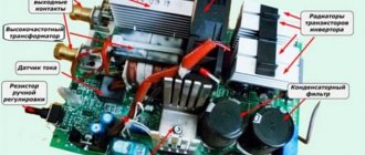
Converter. Power part of the welding machine
Below is the so-called “power” part.
Specification of “power section” parts
0.1 µF x 250 V
| Designation on the diagram | Item brand | Notes |
| DIODES | ||
| VD1 - VD8 | KD 203 | Installed on radiators |
| VD9 - VD11 | KD 226D | |
| VD12 | KD 102B | |
| VD13 | KD 522 | |
| VD14, VD15 | KD 102A | |
| VD16 - VD17 | KD 213A | |
| VD18 - VD19 | KD 212A | |
| VD20 - VD21 | KD 212A | |
| VD22 - VD27 | KD 209A | |
| VD28 - VD29 | KS162A | |
| VD30 | KD 2990A (KD 2997A) | |
| VD31 - VD42 | KD 2997A | |
| THYRISTOR | ||
| VT1 | T122-25-6 | Installed on the radiator |
| TRANSISTORS | ||
| VT2 - VT3 | KT 315G | |
| VT4 | KT 209M | |
| VT5 - VT6 | KT 972A | |
| VT7 - VT8 | KT 878A | Installed on the radiator |
| MICROCIRCUITS | ||
| DA1 | 142KREN5A | |
| TRANSFORMERS, CHOCKS | ||
| T1 | See notes | See winding data |
| T2 | Ш10х10 NM-2000 | |
| T3 | K12x8x3 NM-2000 | |
| T4 - T5 | 2xK20x10x NM-2000 | |
| T6 | 2xK28x16x9 NM-2000 | |
| T7 | 2xWx20x28 NM-2000 | |
| L1 - L4 | PH 4748003 (for some reason they are made on hardware.) | (used in BP computer "ES") |
| RESISTORS | ||
| R1 | 10 Ohm at least 5 W | |
| R2 | 10 kOhm 2 W | |
| R3 | Variable 1kOhm | |
| R4 | 1 kOhm | |
| R5 | 22 kOhm | |
| R6 | 150 kOhm | |
| R7 | 10 kOhm | |
| R8 | 27 kOhm | |
| R9 | 10 kOhm | |
| R10 | 10 kOhm 2 W | |
| R11 | 1.5 kOhm | |
| R12 | 1.8 kOhm | |
| R13-15 | General: 470 Ohm at least 25 W | |
| R16 - R17 | 0.5 Ohm 2 W | |
| R18 - R20 | General: 0.01 Ohm at least 5 W | |
| R21, R23 | 2.2 kOhm | |
| R22, R24 | 6.8 kOhm | |
| R25 | 1.2 kOhm | |
| R26 | 68 kOhm | |
| R27 - R28 | 750 Ohm | |
| R29 | 200 Ohm | |
| R30 | Variable 1kOhm | |
| R31 - R34 | 47 Ohm | |
| CAPACITORS | ||
| C1 | 0.47 µF x 800 V | |
| C2 | 10.0 µF x 350 V | |
| C3 | 0.047 µF x 600 V | |
| C4 | 0.022 µF | |
| C5 | 0.1 µF x 50 V | |
| C6 | 0.1 µF | |
| C7 | 0.047 µF | |
| C8 | 0.047 µF x 800 V | |
| C9 - C12 | Total 2000.0 µF x 350 V | |
| C13 | Selected during setup | |
| C14 | Selected during setup | |
| S15, S16 | 56 pF | |
| C17 | ||
| C18 | 470.0 µF x 35 V | |
| S19, S21, S23, S25, S27, S29, S31 | 0.1 µF | |
| S20 | 470.0 µF x 16 V | |
| S22, S26, S30 | 10.0 µF x 16 V | |
| S24, S28 | 68.0 µF x 35 V | |
| C31 - C34 | 0.022 µF |
Control circuit: master oscillator, comparator, trigger circuit.
Control circuit and part of the starting circuit:
Control Circuit Parts Specification
| Designation on the diagram | Item brand | Notes |
| DIODES | ||
| VD1 | KD503 | Any low power |
| TRANSISTORS | ||
| VT1, VT8, VT9 | KT315 | Any analogues are possible |
| VT2 - VT5 | KT361 | Any analogues are possible |
| VT6, VT7 | KT605BM | Any analogues are possible |
| MICROCIRCUITS | ||
| DA1 | K155LA3 (LA12) | Any analogues are possible |
| DA2 | K544CA3 | |
| DA3 | K155AG3 | |
| DA4 | K155TM2 (K1531TM2) | Any possible |
| DA5 | K155LA1 (K155LA6) | Any analogues are possible |
| RESISTORS | ||
| R1, R2, R5, R8, R10 | 2.2-4.7 kOhm | Depending on the chips used |
| R3 | 27 kOhm | |
| R4 | 4.3 kOhm | |
| R6 | Selected during setup | In the reference book on microcircuits, edited by Shilo, there are graphs for calculating the duration of pulses received from the 155AG3 monovibrator |
| R7 | Selected during setup | |
| R9 | 330 Ohm | |
| R11, R13, R15, R17 | 3.3 kOhm | |
| R12, R14, R16, R18 | 2.7 kOhm | |
| R19, R21 | 680 Ohm | |
| R20, R22 | 1.5 kOhm | |
| R23, R24 | 1.2 kOhm | |
| CAPACITORS | ||
| C1 | 1000 pF | |
| C2 | 56 pF | |
| C3 | Selected during setup | In the reference book on microcircuits, edited by Shilo, there are graphs for calculating the duration of pulses received from the 155AG3 monovibrator |
| C4 | Selected during setup | |
| C5 | 1000 pF |
PCB drawing:
Layout of elements on the board
Please note that the “soft start” circuit (except for elements R1, C2) is located on the control board.