Types of welding machines
To make a welding machine with your own hands, you need to delve into the essence of the issue and choose one scheme to implement your plan, and then start purchasing components.
Depending on certain parameters, it is customary to distinguish between the following types of units:
- On alternating current.
- On direct current.
- Three-phase.
- Inverter.
The first type listed in the list is considered the simplest; if you want to create a second version of the device, you need to introduce a special block and an anti-aliasing filter into the design.
Three-phase models can be found in industry; it is irrational to choose such units for home use.
Advice! The inverter type is a more complex device; without basic knowledge of board assembly and understanding of circuits, professionals do not recommend attempting to create it yourself.
Hello. What if the transformer is W-shaped? Can you advise? I'm assembling a welding machine.
Hello, Alexander. The operating principle is the same. However, send photos to the site’s email (see section “About the site”) and describe the dimensions of the magnetic core iron. This will help me make a power calculation. Also read the comments to the article about the design of the homemade Moment soldering iron. There I devoted a lot of time to this issue. You will need it.
Read also: Micrometer purpose and device
Hello Dear Alexey! Thank you for your article, very useful and interesting! Tell me, I have a couple of questions! My initial power source is already ready 36 volts DC, if I exclude the very beginning of the so-called transformer from this circuit, will this circuit work? Or is it not suitable for me? Need something else? I'll be looking forward to your answer! thank you in advance!
Hello, Pavel. I didn't quite understand your question. Let's clarify: you have a ready-made voltage source that gives an output of 36 volts. Did I understand correctly that you want to use it to make a DC welder? For reliable arc ignition you need 60-70 volts. In my case, it turned out to light it from 50. I didn’t experiment below, try it, but it’s unlikely that you’ll get anything good... One more important electrical characteristic is the output power. If this is not provided, the welding machine will simply burn out. I created it at 50Vx160A=8kW. Pay attention to the power circuits of your source, will they withstand such power? Actually, I advise you to do the calculation based on the initial problem: what electrodes are you going to use to cook and cut. It is necessary to create an electric arc current under them and ignite it. This will determine the output power of the welder. The design is calculated and parts are selected based on these parameters. Send us a photo of your unit. Or better yet, a diagram. Then it will be possible to give more specific recommendations.
Victor, the ignition voltage depends on the characteristics of the welding electrode. With the right choice of electrode, welding work goes well at Ux.x. welder 36 volts or less.
Thanks for the addition. Alexander. Pavel has already explained this to me too. I'm just not a welder, but a simple electrician.
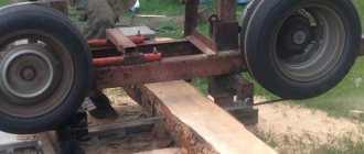
I work as a welder in the north, I travel urgently to emergency situations! Situations often began to occur when the welding generator needed to be dragged directly into the swamp or to perform certain welding jobs - this was very difficult and sometimes extremely impracticable! But I go to the site on a tracked all-terrain vehicle with 24 volt batteries installed. It is not difficult to remove them and quickly bring them to the place! 24 volts does not cook well, but when connecting the battery. up to 36 volts cooks perfectly! but last week a situation happened that I tried to weld the break for too long and my battery exploded! Dear Alexey, I ask you to help me in this matter because after reading your article I realized that you are a professional in this matter! Is it possible to adjust your circuit to 36 volts DC, or 24 if necessary, I can connect two to 48 volts
Well, I use 2.0 and 2.5 mm electrodes, sometimes I use 3 mm. current for them from 70 to 110 amperes for the eyes 36 volts cooks well, well, more precisely, it cooked! As you understand, it was shorted to a straight line! I understand that, of course, this is nonsense and everything should be correct and according to science! That's why I turned to you! 110 is even a lot, rarely when I set it to more than 100 it means 70-100 amperes
Pavel, doing welding from a battery assembly is not the best option, but it works quite well for emergency situations. We must take into account the risk of losing the battery. What needs to be taken into account in my opinion: 1. All banks must be well charged. Any defective bank will work to discharge the battery, taking its current onto itself. 2. Welding must be done quickly. Otherwise, the electrolyte will boil and the battery will explode. Before my eyes, while serving in the army, a mechanic driver of a self-propelled tractor dropped a wrench about 22x24 in size onto the battery output tires. The arc was such that the key burned out, but the banks survived. They started a diesel engine with 500 horses. I don’t remember the amps, but the assembly was made from tank batteries. It was difficult to drag them even with two people. I return to our welding. We assume that the maximum current should be 110 amperes. It should be issued by the battery. A voltage of 48 volts should be sufficient. If you worked from 36, then you can also use it, but 48 is better. The mode of short circuiting batteries through the electrode is not very good. It must be limited by electrical resistance. For DC circuits, I recommend using a CMOS series bipolar transistor. The control circuit that I made for a welder using rectified current will not work. Here it is pure constant and everything works differently. I’ll think about the scheme tomorrow and propose something that, in my opinion, is most suitable.
Pavel, I haven’t found a decent circuit that a beginner with minimal electronics skills can assemble. Many mistakes can be made. I propose to connect an inverter to the battery, converting constant voltage into 220 volts, and power the welding inverter from it. All this equipment can be simply purchased. The heating of the electrolyte in batteries must be controlled; it must not be allowed to boil.
Good day Pavel, I have such a device as ISKRA Universal vd 0801 knot. I encountered this factor while working. During operation, it buzzed very loudly and the diodes flew out. I replaced all 16 diodes with new ones. turned it on and inserted the jumper into the block. and everything happened again. what could be the problem. There is very little said on the Internet about such a device, maybe you can help. thank you in advance
Hello, Ivan. I have not encountered such a device, there is no diagram. What I found on the Internet raises doubts and requires verification. However, we have experience with repairing such devices. I think we'll repair it. I need a diagram and detailed photos. Send what you have to the site's email. I will get acquainted with the design and tell you what to do. You will need a multimeter or an old tester for electrical measurements. Battery, flashlight bulb. wires. I'm waiting for additional information.
List of materials and tools
When carefully familiarizing yourself with the design of a welding machine operating on alternating current, you need to know that such samples have a primary winding of 220 volts, and on the secondary winding it drops to 50-60 volts, after which it goes to the electrode in contact with the workpiece.
Before you begin assembling the equipment, you should prepare or purchase the following items:
- Magnetic core.
- Cable for coil winding.
- Materials for insulating connections.
Experts consider the factory transformer to be the most versatile workpiece; some parts are perfect for making simple models yourself. We are talking about a magnetic circuit and a primary winding, but when such components are not available, the element must be created from scratch.
How to make a welding unit with your own hands?
After studying the main features of the assembly process, you can proceed directly to assembling homemade equipment.
Today, there are a large number of different methods and recommendations on how best to assemble a homemade welding machine of any kind - with alternating or direct current, pulsed or inverter, automatic or semi-automatic.
There is no need to go deep enough into this topic, since one of the easiest ways to assemble a welding machine with your own hands is to use a transformer.
Its peculiarity is that it works with alternating current, which ensures the creation of a high-quality seam when welding metal surfaces. Such equipment can cope with any household work where it is necessary to weld metal or steel structures.
To make it you need to prepare:
- Several meters of cable with great thickness.
- Material for the core that will be located in the transformer. The material itself must have increased permeability with magnetization.
The best option is when the rod-shaped core has the letter “P”. In some cases, it is allowed to use this part in a more modified form, for example, a round stator made from a damaged electric motor.
Diagram of a welding transformer.
However, it is worth paying attention that it is more difficult to wind windings onto this shape. It is best when the core cross-section for classic welding equipment, made by hand and used for domestic purposes, had an area of about 50 cm2.
In order for the equipment to have an accessible weight, it is not necessary to increase the cross-section in volume, however, the technical effect will not be at the highest level. If the cross-sectional area does not suit you, then you can calculate it yourself using special diagrams and formulas.
The primary winding must be made of copper wire, which will have increased characteristics: thermal resistance, since during operation of the structure this part heats up very much.
Such a part must have cotton or fiberglass insulation. As a last resort, it is possible to use rubber insulated wire or rubber cloth, but beware of PVC winding.
The insulation is also made by hand, using cotton or fiberglass, or rather parts of it 2 cm wide. Thanks to these pieces, you can wrap the wire and then impregnate it with any varnish for electrical purposes. This insulation will not overheat after regular use.
Similar to the above calculations, it will be possible to calculate which cross-sectional area of the winding - primary and secondary - will be the most optimal. Often the secondary winding has an area of about 30 mm2, and the primary winding up to 7 mm2, using a rod of 4 millimeters in diameter.
In addition, in a simple way you need to determine how far a piece of copper wire will stretch and how many turns will be needed to wind two windings. After this, the coils are wound, and the frame is made using the geometric parameters of the magnetic core.
The main thing is to ensure that there are no difficulties when putting on the magnetic core. First of all, you need to choose the correct core size. It is best made using electrical cardboard or textolite.
Using the same analogue, it will be possible to make a structure for welding small parts. For home use, you can use a small mini welding machine.
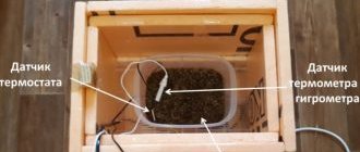
Microwave power supply
The considered welding machine circuit after assembly should produce a minimum of 4 kW; if we take the element from a microwave oven, which has a rating of 1.2 kW, as the main part, it will not be enough.
For operation, two transformers should be selected, which will subsequently need to be connected to each other.
The detailed algorithm of actions looks like this:
- By powering two parts to a 220-volt network, the integrity of the winding is checked.
- To remove the high-voltage winding, you need to cut the magnetic core.
- The coil is removed from the chain.
- From a copper bus of 10 sq. mm the core is manufactured.
- A dielectric spacer is created under the primary winding.
- The coil and magnetic circuit are connected.
- All cables are connected in accordance with the diagram.
After installing the electrode in the holder, you can begin to check the functionality of the created unit; there is no need to take markings with a diameter of more than 4-5 mm.
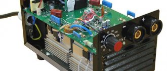
Diagnostics of a homemade inverter and its preparation for operation
Making an inverter welding machine is half the battle. An equally important task is its preparation for work, during which the correct functioning of all elements is checked, as well as their settings.
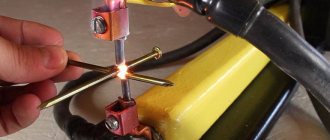
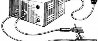
The first thing you need to do when checking a homemade welding inverter is to apply a voltage of 15 V to the PWM controller and one of the cooling fans. This will allow you to simultaneously check the functionality of the controller and avoid overheating during such a test.
Checking the output voltage with a tester
After the capacitors of the device are charged, a relay is connected to the electrical supply, which is responsible for closing the resistor. If you apply voltage directly to the resistor, bypassing the relay, an explosion may occur. After the relay operates, which should happen within 2-10 seconds after applying voltage to the PWM controller, you need to check whether the resistor has shorted.
When the relays of the electronic circuit operate, rectangular pulses should be generated on the PWM board and supplied to the optocouplers. This can be checked using an oscilloscope. The correct assembly of the diode bridge of the device also needs to be checked; for this, a voltage of 15 V is applied to it (the current should not exceed 100 mA).
The transformer phases may have been incorrectly connected when assembling the device, which can lead to incorrect operation of the inverter and the generation of strong noise. To prevent this from happening, the correct phase connection must be checked using a dual-beam oscilloscope. One beam of the device is connected to the primary winding, the second to the secondary. The phases of the pulses, if the windings are connected correctly, should be the same.
Using an oscilloscope to diagnose an inverter
The correct manufacturing and connection of the transformer is checked using an oscilloscope and connecting electrical devices with different resistances to the diode bridge. Based on the noise of the transformer and the readings of the oscilloscope, they conclude that it is necessary to improve the electronic circuit of the homemade inverter apparatus.
To check how long you can continuously work on a homemade inverter, you need to start testing it from 10 seconds. If the device’s radiators do not heat up during operation for such a duration, you can increase the period to 20 seconds. If such a time period does not negatively affect the condition of the inverter, you can increase the operating time of the welding machine to 1 minute.
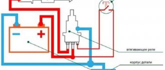
DC equipment
People who professionally repair welding machines can confidently call this model more stable when considering the characteristics of the arc. An auxiliary component is responsible for the process of voltage transfer, which is known to many as a converter, supplemented by a smoothing element.
With such a device, you can weld not only the usual type of metal, but also cast iron or stainless steel, since the seam is as smooth and neat as possible.
- Before starting assembly, you will need to purchase powerful diodes or transistors in the amount of 4 pieces, each copy must have a rating of 200 A.
- The design includes a capacitor with a capacity of 15 thousand uF and a choke; when working independently, you should be guided by a special circuit.
Important! During operation of the transformer, overheating may occur, which will lead to rapid failure of the diodes; to prevent this excess, the structure is equipped with a device for heat removal.
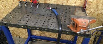
Welding rectifier - features of operation and assembly
To perform certain types of welding work, for example, with stainless steel, the use of alternating current supplied by a transformer is not used. To work with such metals, a constant voltage supply is required. In addition, direct current cutting reduces the consumption of electrodes, and metal spattering is prevented during welding.
To perform work in such conditions, welding rectifiers are used, which allow welding with direct and reverse polarity current. If you have experience in installing electronic circuits, then you can also assemble such a device yourself.
The basis of the welding rectifier will be the same step-down transformer. The difference lies in the presence of a rectifying electronic circuit. If desired, you can remake the already described welding transformer or assemble a universal device that will allow you to weld with both alternating and direct current.
The simplest diagram of the electronic part of a welding rectifier looks like this:
Schematic diagram of a welding rectifier
When assembling such devices, the following design features should be taken into account:
- The main part of the device is a rectifier bridge made of powerful power diodes. They are connected according to the diagram, taking into account polarity.
- Smoothing of current ripple is carried out due to a filter made on the capacitor and choke coil. Please note that the components must have a margin of 2.5 - 3 permissible voltage.
- When working with high currents, the elements heat up. Semiconductor diodes are sensitive to overheating. Therefore, they are installed on radiators, which will increase the intensity of heat removal.
- When enclosing the device in a housing, it becomes mandatory to use a fan to increase cooling efficiency.
We pay attention to the connection of individual elements of the circuit. Considering that they will be exposed to high current, it is necessary to ensure reliable contact. If this is not done, then the wires in these areas will heat up and burn out. The preferred option is with fastening using platforms with a bolt and nut.
The choke in such designs is made in the form of a separate remote inductor, which is connected as needed. Note that installing a rectifier does not prevent the welding current from changing using the secondary winding coil position regulator.
As you can see, there are no difficulties in assembling a welding machine yourself. But it’s worth working on such devices only if you have experience in designing simple devices that operate with lower currents. Otherwise, entrust the assembly to a specialist or buy a factory welding machine.
Microwave welding machine:
Unit with small dimensions
A well-assembled inverter welding machine is no less useful both in production and at home when repairing cars or small items.
Thanks to this type of device, it is possible to implement spot welding, which in some situations will be much more convenient, besides, the weight and dimensions of the box are quite compact, it can be easily carried by hanging it on your shoulder.
The design includes:
- Diode rectifier.
- Management system.
- Power part.
- Diode and choke.
- Cooler for cooling.
- Feedback to control parameters.
When creating a model, you will need to wind a power transformer yourself, the base of which will be a ferrite ring. Professionals advise purchasing a ready-made assembly of semiconductor elements for the bridge; some components cannot be found at home; they are often ordered or bought in specialized stores.
The device is considered quite complex; without self-confidence, suitable circuits and basic skills, you should not undertake the process.
Having started to implement their plans, many owners noticed that independently constructing an inverter model is no cheaper than factory products, so it is most rational to buy a ready-made unit with specified operating parameters.
Video instructions will be no less practical; thanks to them, you will be able to understand all the stages of work on creating equipment much faster.
Features of winding windings.
There are the following rules for winding the windings of a welding machine:
- Winding should be done along an insulated yoke and always in the same direction (for example, clockwise).
- Each winding layer is insulated with a layer of cotton insulation (fiberglass, electrical cardboard, tracing paper), preferably impregnated with bakelite varnish.
- The terminals of the windings are tinned, marked, secured with cotton braid, and a cotton cambric is additionally put on the terminals of the network winding.
- If the wire insulation is of poor quality, winding can be done in two wires, one of which is a cotton cord or cotton thread for fishing. After winding one layer, the winding with cotton thread is fixed with glue (or varnish) and only after it has dried, the next row is wound.
The network winding on a rod-type magnetic core can be positioned in two main ways. The first method allows you to obtain a more “hard” welding mode. The network winding consists of two identical windings W1, W2, located on different sides of the core, connected in series and having the same wire cross-section. To regulate the output current, taps are made on each of the windings, which are closed in pairs.
The second method of winding the primary (network) winding involves winding a wire on one side of the core. In this case, the welding machine has a steeply falling characteristic, welds “softly”, the length of the arc has less influence on the value of the welding current, and therefore on the quality of welding.
After winding the primary winding of the welding machine, it is necessary to check for the presence of short-circuited turns and the correct number of turns. The welding transformer is connected to the network through a fuse (4...6 A) and if there is an AC ammeter. If the fuse burns out or gets very hot, this is a clear sign of a short-circuited turn. In this case, the primary winding must be rewound, paying special attention to the quality of the insulation.
If the welding machine makes a loud noise and the current consumption exceeds 2...3 A, then this means that the number of turns of the primary winding is underestimated and it is necessary to wind up a certain number of turns. A working welding machine should consume no more than 1..1.5 A current at idle, not get hot and not make a strong buzz.
The secondary winding of the welding machine is always wound on both sides of the core. According to the first winding method, the secondary winding consists of two identical halves, connected counter-parallel to increase the stability of the arc (Fig. 6 b). In this case, the wire cross-section can be taken slightly smaller, that is, 15..20 mm2. When winding the secondary winding using the second method, first 60...65% of the total number of its turns is wound on the side of the core free from windings.
This winding serves mainly to ignite the arc, and during welding, due to a sharp increase in magnetic flux dissipation, the voltage on it drops by 80...90%. The remaining number of turns of the secondary winding in the form of an additional welding winding W2 is wound on top of the primary. Being a power supply, it maintains the welding voltage and, consequently, the welding current within the required limits. The voltage across it drops in welding mode by 20...25% relative to the no-load voltage.
Winding the windings of a welding machine on a toroidal core can also be done in several ways.
Methods for winding the windings of a welding machine on a toroidal core.
| 1. Uniform; | 2. Sectional; |
| a - network winding; | b - power winding |
Switching windings in welding machines is easier to do with the help of copper tips and terminals. Copper lugs at home can be made from copper tubes of a suitable diameter with a length of 25...30 mm, securing the wires in them by crimping or soldering. When welding under different conditions (high or low current network, long or short supply cable, its cross-section, etc.), by switching the windings, the welding machine is adjusted to the optimal welding mode, and then the switch can be set to the neutral position.
Photo of a homemade welding machine
What is needed to assemble an inverter
To assemble inverter welding yourself, you need to know that the circuit is designed, first of all, for a consuming voltage of 220 Volts and a current of 32 Amps. After energy conversion, the output current will increase almost 8 times and reach 250 Amperes. This current is sufficient to create a strong seam with an electrode at a distance of up to 1 cm. To implement an inverter-type power supply, you will need to use the following components:
1) A transformer consisting of a ferrite core.
2) Winding of the primary transformer with 100 turns of wire with a diameter of 0.3 mm.
3) Three secondary windings:
— internal: 15 turns and wire diameter 1 mm;
- medium: 15 turns and diameter 0.2 mm;
— external: 20 turns and diameter 0.35 mm.
In addition, to assemble the transformer, you will need the following elements:
- copper wires;
- fiberglass;
— textolite;
— electrical steel;
- cotton material.