The concept of metal surface quality after processing
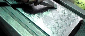
After processing on a milling machine, as after other work with the workpiece, irregularities are formed on its surface - ridges and depressions (in other words, roughness and waviness). Residual stress also appears in the upper layers of the material; at some rolling depths, a difference in hardness appears, which manifests itself as hardening or hardening. Such changes affect the properties of finished products and, consequently, the quality of their surfaces. All these characteristics determine the class of metal processing.
The quality of finished parts is determined by both their physical and geometric characteristics.
- Physical quality criteria.
The surface quality of a product is determined by the relationship between the physical and mechanical properties of its central part and its outer part.
During the processing of metal workpieces, their surface is subject to plastic changes, therefore other characteristics of the material in the finished product differ from the original ones. At the same time, the outer part of the plate is strengthened and internal stresses appear in it.
After the final stage of metal processing on a milling machine, the hardened layer extends only a few hundredths of a millimeter, while after the initial impact of a cylindrical cutter its thickness averages 0.04–0.08 mm, reaching 0.12 mm. When exposed to an end mill, the parameter is 0.06–0.1 mm, although it can be 0.2 mm. The resulting internal stresses and surface hardening lower the class of metal processing by reducing the fatigue strength of the product. Such deformations shorten the service life of the part, which leads to the need for its immediate replacement.
During rough rough processing with a gear cutter at high speeds and with an increased depth of section, irregularities remain on the edge of the product, which are noticeable to the naked eye and are easily determined by touch. Roughness and waviness formed during intermediate and finishing machining at low speeds and during shallow cutting are visually invisible and can barely be felt.
The class of geometric accuracy of metal processing depends on the presence of irregularities on the surface of the product: depressions, ridges, roughness, etc. Such defects on a small surface area are called its microgeometry.
The microgeometry of the surface when processing rolled products depends on:
- cutter geometry, its quality and degree of wear;
- vibrations arising due to insufficient rigidity of the machine or its working elements;
- established settings for the operation of the milling machine (cutting speed and depth, feed per tooth, cooling);
- mechanical properties of the processed sheet and the cutter itself.
Surface roughness when processed with tools
Surface roughness classes
Factors affecting surface quality
Surface roughness depends on the processing method and mode, the quality of the cutting tool used, the rigidity of the technological system, the physical and mechanical properties of the material being processed, the type of coolant used, vibrations of the technological system, etc.
Each processing method (turning, grinding, etc.) has its own range of surface roughness. In table Table 3.1 shows the surface roughness for various methods of processing steel and gray cast iron and compares the roughness parameters with the parameters of average economic accuracy. From a comparison of these parameters, one can see their relationship: the higher the accuracy of the resulting size, the lower the surface roughness.
Further, on page 7, see table. 3.1.
Roughness table
| № | Surface roughness classes | Roughness parameters, microns | Base length, l, mm | |
| Ra | Rz | |||
| 1. | 2. | 3. | 4. | 5. |
| 1. | 1 | 80, 63, 40, 50* | 320, 250, 200, 160 | 8,0 |
| 2. | 2 | 40, 32, 20, 25* | 160, 125, 100, 80 | |
| 3. | 3 | 20, 16, 10, 12,5* | 80, 63, 50, 40 | |
| 4. | 4 | 10, 8, 5, 6,3* | 40, 32, 25, 20 | 2,5 |
| 5. | 5 | 5, 4, 2,5; 3,2* | 20, 16, 12,5; 10,0 | |
| 6. | 6 | 2,5; 2,0; 1,25; 1,6* | 10,0 8,0; 6,3 | 0,8 |
| 7. | 7 | 1,25; 1,00; 0,63; 0,80* | 6,3; 5,0; 4; 3,2 | |
| 8. | 8 | 0,63; 0,50; 0,32; 0,40* | 3,2; 5,2; 2,0; 1,6 | |
| 9. | 9 | 0,32; 0,25; 0,160; 0,20* | 1,6; 1,25; 1,00; 0,80 | 0,25 |
| 10. | 10 | 0,160; 0,125; 0,080; 0,10* | 0,80; 0,63; 0,50; 0,40 | |
| 11. | 11 | 0,080; 0,063; 0,040 | 0,40; 0,32; 0,25; 0,20 | |
| 12. | 12 | 0,040; 0,032; 0,020 | 0,20; 0,16; 0,125; 0,100 | |
| 13. | 13 | 0,020; 0,016; 0,010 | 0,100; 0,080; 0,063; 0,050 | 0,08 |
| 14. | 14 | 0,010; 0,008; 0,012* | 0,050; 0,040; 0,032 |
Note: * - preferred values of Ra parameters
Examples:
Designations of surface roughness in drawings
Table 3.1
| Processing method | The corresponding qualification is exact. | Surface roughness Ra, microns | Processing method | The corresponding qualification is exact. | Surface roughness Ra, microns |
| Turning: preliminary…………….. finishing…………………fine, diamond……………. Milling: preliminary……………. finishing………………………thin (with end mills).. Drilling: Countersinking: preliminary………………. finishing (after roughing)… Broaching holes…… | 12 — 13 10 — 11 6 – 7 11 — 12 8 – 10 6 – 7 11 — 12 7 – 8 | 12,5 2,5 – 1,25 0,63-0,32 12,5 2,5-1,25 0,63-0,32 6,3-2,5 2,5-12,5 6,3-2,5 1,25-0,63 | Stitching (for short holes) ………………….. Grinding: rough*…………. preliminary……. finishing ……………… thin ………………… Honing of holes with a diameter of up to 80 mm …………. Reaming: preliminary…………….. finishing……………………… thin……… Lapping in (finishing)…………. Polishing **………………… | — 8-10 7-8 6-7 6-7 8-9 6-7 5-6 — | 0.63-0.32 2.5-1.25 1.25-0.63 0.63-0.32 0.32-0.08 0.32-0.08 2.5-1.25 1 .25-0.63 0.63-0.32 0.1 and less 0.032-0.012 |
* Rough grinding is used as a preliminary treatment of the surfaces of castings and forgings, without maintaining dimensional tolerances.
** This method does not improve the accuracy of the size obtained in previous processing.
When processing workpieces with blade tools, the surface roughness largely depends on the cutting speed and feed. In Fig. 3.5, a shows the effect of cutting speed on surface roughness when turning steel (curve 1) and cast iron (curve 2). After turning a steel workpiece at a cutting speed of about 20 m/min (curve 1), the greatest roughness is observed, which is associated with the phenomenon of active formation of built-up edge on the cutting part of the cutter. At cutting speeds above 80 m/min, the formation of built-up edge practically stops. In addition, at high cutting speeds, the depth of the plastically deformed layer is significantly reduced, which also reduces the surface roughness.
In Fig. Figure 3.5, b shows the dependence of surface roughness on feed when turning a workpiece made of steel 45 with a cutter with a tip radius of 2.5 mm. The figure shows that changes in small feeds (up to 0.2 mm/rev) have little effect on the change in surface roughness. But when moving to the feed range above 0.2 mm/rev, the microroughness of the machined surface increases more intensively.
Rice. 3.5. Graphs of surface roughness versus cutting speeds and feeds
With increasing cutting depth, surface roughness increases slightly and practically can be ignored.
The condition of the cutting part of the tool has a significant influence on the surface roughness: micro-roughness of the cutting edge of the tool worsens the roughness of the machined surface; this is especially noticeable when processing with broaches, reamers or wide cutters. Dulling of the cutting tool leads to an increase in the roughness of the machined surface.
When processing workpieces with an abrasive tool, the surface roughness decreases with a decrease in grain size and an increase in the hardness of the grinding wheel, an increase in cutting speed, and a decrease in longitudinal and transverse feeds.
When machining steel with a high carbon content (C > 0 5%), a cleaner surface is obtained than when machining low-carbon steel.
The use of a cutting fluid improves the roughness of the machined surface. At the same time, tool life increases. In Fig. Figure 3.6 shows (according to K. S. Kolev) the effect of cooling on the microgeometry of the surface when turning X4N steel with a high-speed cutter at a feed S = 0.67 mm/rev: 1 - turning without the use of cooling; 2 - cooling with a water emulsion (0.5% soda and 0.1% soap).
The rigidity of the process system significantly influences the surface roughness and waviness. So, for example, when turning a non-rigid shaft with installation on centers, the greatest surface roughness is obtained approximately in the middle part along the length of the shaft. Insufficient rigidity of the system can cause vibration during cutting and, as a result, the formation of a wavy surface.
Rice. 3.6. Rice. 3.7.
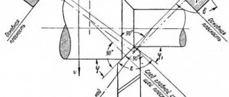
The physical and mechanical properties of the surface layer of parts and workpieces largely depend on the influence of thermal and force factors during processing. The surface layer of the processed steel workpiece consists of three zones (Fig. 3.7): I – zone of pronounced deformation, characterized by distortion of the crystal lattice, grain fragmentation and increased hardness; II – deformation zone, characterized by elongated grains and a decrease in hardness compared to the first zone; III - transition zone (zone of gradual transition to the structure of the base metal).
Initial steel blanks obtained by forging, casting or rolling have a surface layer consisting of a decarburized zone and a transition zone, i.e., a zone with partial decarburization. For example, workpieces produced by hot stamping have a decarburized layer in the range of 150-300 microns, and those obtained by free forging - from 500 to 1000 microns.
When processing steel workpieces by cutting, the depth of deformation extends to 100-300 microns. For cast iron workpieces, the depth of deformation is insignificant (up to 15 microns).
During mechanical processing of metals, deformation of the surface layer is accompanied by hardening (hardening) of this layer. With increasing cutting depth and feed, the depth of the hardened layer increases. So, for example, during rough turning the work hardening depth is 200-500 µm, during finishing turning 25-30 µm, during grinding 15-20 µm and during very fine processing 1-2 µm.
Rice. 3.8. Rice. 3.9.
With increasing cutting speed, the depth of work hardening decreases. This is explained by a decrease in the duration of the action of cutting forces on the deformed metal. In Fig. Figure 3.8 shows (according to K.S. Kolev) the influence of cutting speed v during turning of steel ZOKHGS (curve 1) and steel 20 (curve 2) on hardening Hd.
When grinding parts, the dominant factor is thermal, which causes tensile stresses to appear in the surface layer of the metal being processed. In Fig. Figure 3.9 shows a diagram of the distribution of residual stresses σ after grinding to a depth h of the surface layer (curve 1). The appearance of tensile stresses is associated with rapid heating of the surface layer in the area of contact between the metal of the part and the grinding wheel. After passing the grinding wheel, the surface layer, cooling, tends to shrink, causing tensile stresses. When grinding with curing (i.e., with subsequent switching off of the longitudinal feed), tensile stresses significantly decrease and compressive stresses increase (curve 2).
Surface roughness classes
Factors affecting surface quality
Surface roughness depends on the processing method and mode, the quality of the cutting tool used, the rigidity of the technological system, the physical and mechanical properties of the material being processed, the type of coolant used, vibrations of the technological system, etc.
Each processing method (turning, grinding, etc.) has its own range of surface roughness. In table Table 3.1 shows the surface roughness for various methods of processing steel and gray cast iron and compares the roughness parameters with the parameters of average economic accuracy. From a comparison of these parameters, one can see their relationship: the higher the accuracy of the resulting size, the lower the surface roughness.
Further, on page 7, see table. 3.1.
Roughness table
| № | Surface roughness classes | Roughness parameters, microns | Base length, l, mm | |
| Ra | Rz | |||
| 1. | 2. | 3. | 4. | 5. |
| 1. | 1 | 80, 63, 40, 50* | 320, 250, 200, 160 | 8,0 |
| 2. | 2 | 40, 32, 20, 25* | 160, 125, 100, 80 | |
| 3. | 3 | 20, 16, 10, 12,5* | 80, 63, 50, 40 | |
| 4. | 4 | 10, 8, 5, 6,3* | 40, 32, 25, 20 | 2,5 |
| 5. | 5 | 5, 4, 2,5; 3,2* | 20, 16, 12,5; 10,0 | |
| 6. | 6 | 2,5; 2,0; 1,25; 1,6* | 10,0 8,0; 6,3 | 0,8 |
| 7. | 7 | 1,25; 1,00; 0,63; 0,80* | 6,3; 5,0; 4; 3,2 | |
| 8. | 8 | 0,63; 0,50; 0,32; 0,40* | 3,2; 5,2; 2,0; 1,6 | |
| 9. | 9 | 0,32; 0,25; 0,160; 0,20* | 1,6; 1,25; 1,00; 0,80 | 0,25 |
| 10. | 10 | 0,160; 0,125; 0,080; 0,10* | 0,80; 0,63; 0,50; 0,40 | |
| 11. | 11 | 0,080; 0,063; 0,040 | 0,40; 0,32; 0,25; 0,20 | |
| 12. | 12 | 0,040; 0,032; 0,020 | 0,20; 0,16; 0,125; 0,100 | |
| 13. | 13 | 0,020; 0,016; 0,010 | 0,100; 0,080; 0,063; 0,050 | 0,08 |
| 14. | 14 | 0,010; 0,008; 0,012* | 0,050; 0,040; 0,032 |
Note: * - preferred values of Ra parameters
Examples:
Designations of surface roughness in drawings
Table 3.1
| Processing method | The corresponding qualification is exact. | Surface roughness Ra, microns | Processing method | The corresponding qualification is exact. | Surface roughness Ra, microns |
| Turning: preliminary…………….. finishing…………………fine, diamond……………. Milling: preliminary……………. finishing………………………thin (with end mills).. Drilling: Countersinking: preliminary………………. finishing (after roughing)… Broaching holes…… | 12 — 13 10 — 11 6 – 7 11 — 12 8 – 10 6 – 7 11 — 12 7 – 8 | 12,5 2,5 – 1,25 0,63-0,32 12,5 2,5-1,25 0,63-0,32 6,3-2,5 2,5-12,5 6,3-2,5 1,25-0,63 | Stitching (for short holes) ………………….. Grinding: rough*…………. preliminary……. finishing ……………… thin ………………… Honing of holes with a diameter of up to 80 mm …………. Reaming: preliminary…………….. finishing……………………… thin……… Lapping in (finishing)…………. Polishing **………………… | — 8-10 7-8 6-7 6-7 8-9 6-7 5-6 — | 0.63-0.32 2.5-1.25 1.25-0.63 0.63-0.32 0.32-0.08 0.32-0.08 2.5-1.25 1 .25-0.63 0.63-0.32 0.1 and less 0.032-0.012 |
* Rough grinding is used as a preliminary treatment of the surfaces of castings and forgings, without maintaining dimensional tolerances.
** This method does not improve the accuracy of the size obtained in previous processing.
When processing workpieces with blade tools, the surface roughness largely depends on the cutting speed and feed. In Fig. 3.5, a shows the effect of cutting speed on surface roughness when turning steel (curve 1) and cast iron (curve 2). After turning a steel workpiece at a cutting speed of about 20 m/min (curve 1), the greatest roughness is observed, which is associated with the phenomenon of active formation of built-up edge on the cutting part of the cutter. At cutting speeds above 80 m/min, the formation of built-up edge practically stops. In addition, at high cutting speeds, the depth of the plastically deformed layer is significantly reduced, which also reduces the surface roughness.
In Fig. Figure 3.5, b shows the dependence of surface roughness on feed when turning a workpiece made of steel 45 with a cutter with a tip radius of 2.5 mm. The figure shows that changes in small feeds (up to 0.2 mm/rev) have little effect on the change in surface roughness. But when moving to the feed range above 0.2 mm/rev, the microroughness of the machined surface increases more intensively.
Rice. 3.5. Graphs of surface roughness versus cutting speeds and feeds
With increasing cutting depth, surface roughness increases slightly and practically can be ignored.
The condition of the cutting part of the tool has a significant influence on the surface roughness: micro-roughness of the cutting edge of the tool worsens the roughness of the machined surface; this is especially noticeable when processing with broaches, reamers or wide cutters. Dulling of the cutting tool leads to an increase in the roughness of the machined surface.
When processing workpieces with an abrasive tool, the surface roughness decreases with a decrease in grain size and an increase in the hardness of the grinding wheel, an increase in cutting speed, and a decrease in longitudinal and transverse feeds.
When machining steel with a high carbon content (C > 0 5%), a cleaner surface is obtained than when machining low-carbon steel.
The use of a cutting fluid improves the roughness of the machined surface. At the same time, tool life increases. In Fig. Figure 3.6 shows (according to K. S. Kolev) the effect of cooling on the microgeometry of the surface when turning X4N steel with a high-speed cutter at a feed S = 0.67 mm/rev: 1 - turning without the use of cooling; 2 - cooling with a water emulsion (0.5% soda and 0.1% soap).
The rigidity of the process system significantly influences the surface roughness and waviness. So, for example, when turning a non-rigid shaft with installation on centers, the greatest surface roughness is obtained approximately in the middle part along the length of the shaft. Insufficient rigidity of the system can cause vibration during cutting and, as a result, the formation of a wavy surface.
Rice. 3.6. Rice. 3.7.
The physical and mechanical properties of the surface layer of parts and workpieces largely depend on the influence of thermal and force factors during processing. The surface layer of the processed steel workpiece consists of three zones (Fig. 3.7): I – zone of pronounced deformation, characterized by distortion of the crystal lattice, grain fragmentation and increased hardness; II – deformation zone, characterized by elongated grains and a decrease in hardness compared to the first zone; III - transition zone (zone of gradual transition to the structure of the base metal).
Initial steel blanks obtained by forging, casting or rolling have a surface layer consisting of a decarburized zone and a transition zone, i.e., a zone with partial decarburization. For example, workpieces produced by hot stamping have a decarburized layer in the range of 150-300 microns, and those obtained by free forging - from 500 to 1000 microns.
When processing steel workpieces by cutting, the depth of deformation extends to 100-300 microns. For cast iron workpieces, the depth of deformation is insignificant (up to 15 microns).
During mechanical processing of metals, deformation of the surface layer is accompanied by hardening (hardening) of this layer. With increasing cutting depth and feed, the depth of the hardened layer increases. So, for example, during rough turning the work hardening depth is 200-500 µm, during finishing turning 25-30 µm, during grinding 15-20 µm and during very fine processing 1-2 µm.
Rice. 3.8. Rice. 3.9.
With increasing cutting speed, the depth of work hardening decreases. This is explained by a decrease in the duration of the action of cutting forces on the deformed metal. In Fig. Figure 3.8 shows (according to K.S. Kolev) the influence of cutting speed v during turning of steel ZOKHGS (curve 1) and steel 20 (curve 2) on hardening Hd.
When grinding parts, the dominant factor is thermal, which causes tensile stresses to appear in the surface layer of the metal being processed. In Fig. Figure 3.9 shows a diagram of the distribution of residual stresses σ after grinding to a depth h of the surface layer (curve 1). The appearance of tensile stresses is associated with rapid heating of the surface layer in the area of contact between the metal of the part and the grinding wheel. After passing the grinding wheel, the surface layer, cooling, tends to shrink, causing tensile stresses. When grinding with curing (i.e., with subsequent switching off of the longitudinal feed), tensile stresses significantly decrease and compressive stresses increase (curve 2).
Categories of metal processing purity
The cleanliness class of metal processing depends on the degree of roughness of its surface. It is calculated as the height of the irregularities and the frequency of their repetitions. This indicator is influenced by two main factors: the method of influence and the tool used.
There are four categories of metal workpiece processing cleanliness:
- Rough when roughness is visible to the naked eye. It is obtained as a result of manual processing using a large file or using cutters, knives, drills at the initial stage of machine processing.
- Semi-clean when irregularities are barely noticeable or unnoticeable upon visual inspection. Achieved by using a hand-held fine-abrasive file or a specialized machine for finishing.
- Clean when surface defects are visible only when additional tools are used. It is obtained by finishing with a velvet file or using a special grinding unit.
- Very clean when surface irregularities are almost completely absent. Achieved through the use of lapping or high-precision manual grinding with files with a minimum degree of abrasiveness. This class of metal processing purity is considered the reference.
What is surface roughness?
To answer this question, let's think about how parts are made. In any case, in order to give the source material the appearance of the part shown in the drawing, it has to be sawed off, cut, drilled, milled or bent. Bending and other deformations do not particularly concern us now, but the mechanical processing described above does.
When cutting a material, the surface along which the cutting tool passes remains by no means smooth; there will be nicks, scratches and other differences on it. This is surface roughness. They are, of course, not so huge as to be immediately noticeable - their size is in the region of several micrometers. And these dimensions, not surprisingly, are clearly indicated in the corresponding GOST. This is GOST 2789-73 - “Surface Roughness”.
This standard contains a graphic representation of the irregularities in question.
Figure from Wikipedia, the free encyclopedia
When you magnify any surface of the material, you can see a similar picture. Based on the relationships between the roughness parameters indicated in the drawing, several basic types of roughness can be deduced, which we indicate in the drawing.
- Ra is the arithmetic mean deviation of the profile;
- Rz—height of profile irregularities at ten points;
- Pmax—maximum profile height;
- Sm is the average pitch of irregularities;
- S is the average pitch of local profile protrusions;
- tp is the relative reference length of the profile, where p is the level value of the profile section.
When indicating roughness in a drawing, the preferred option is Ra, which is what GOST tells us.
Let's consider the first two options for roughness Ra and Rz.
In the case of Ra, its numerical expression is the arithmetic mean of the absolute values of profile deviations within the base length, and it is formed according to the formula:
where l is the base length, n is the number of selected profile points on the base length.
In the case of Rz, the sum of the average absolute values of the heights of the five largest protrusions of the profile and the depths of the five largest depressions of the profile within the base length is taken:
where ypmi is the height of the i-th largest protrusion of the profile, yumi is the depth of the i-th largest depression of the profile.
In GOST there is a plate that summarizes all possible values of roughness Ra, and the preferred ones are emphasized.
What is plane roughness by type of processing
When manufacturing the required part, in accordance with technical drawings and sketches, various types of processing are used. The initial workpiece is subjected to heating, drilling, cutting and other technological operations.
Each type of processing of a product leaves a certain pattern on its surface in the form of small shagreen, gouges, microscopic cracks and scratches. All these consequences are displayed in the form of roughness on the processed surface of the product.
According to the type of technological impact, a certain class of plane roughness arises. All types and dimensions of this phenomenon are presented in more detail in GOST 2789-73 “ Surface Roughness ” .
The standard contains detailed information with illustrations of roughness. Some types of technical influence leave changes on the surface of the material that are not noticeable to the eye. These roughnesses are studied under a microscope.
The main indicators of shagreen include:
- The height of the treated surface, measured in 10 points;
- Average number of plane deviations;
- Average pitch of irregularities;
- The highest point of the plane after processing;
- Profile reference length.
Finishing metal grinding and polishing of the product maximally levels the surface of the processing, but internal changes at the molecular level in the material leave certain consequences in the form of microscopic shagreen.
What types of surfaces exist
To ensure interchangeability and unification of production, roughness parameters are combined into classes. There are 14 varieties of them in total. Each class is assigned a specific Ra and Rz value. The most accurate class is the fourteenth, the roughest is the first. For this reason, surfaces have also been classified. The following types are found in production:
- Mounting surfaces that are motionless relative to each other and are not subject to tightness requirements. For them, the Ra value is 2.5-20 µm.
- Working surfaces that move relative to each other. This includes piston-cylinder connections, which can often be found in a variety of engines and pumps. Ra for them is 0.16-2.5 microns.
- Bounding and connecting surfaces. This refers to the elements necessary for fastening and assembly. These are all kinds of cases, clamps and other mechanisms. Ra for them ranges from 2.5-20 microns.
- Special surfaces. Here we mainly refer to the controls. The processing of such surfaces is extremely high with their Ra value of 0.63-0.08 µm.
Mechanism of roughness occurrence
All causes of roughness can be divided into 3 groups:
- The location of the cutting edges of the tool relative to the surface being processed;
- Elastic and plastic deformation of the processed metal;
- Vibrations in the technological machine system.
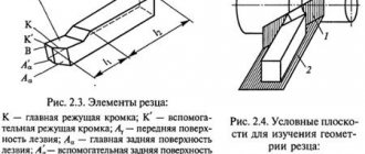
The formation of irregularities on the machined surface can be represented as a trace from the movement of the cutting edges of the tool. Let's call this profile regular.
The formation of a regular profile is influenced by the geometry of the cutter, in particular, the angles in the plan, as well as the feed value S. Their influence is described by the formula
In the actual cutting process, a zone of plastic deformation is formed in front of the cutter and under the machined surface, which introduces some error into the regular profile. Plastically deformed metal in some places seems to be enveloping micro-irregularities, and in some places individual pieces of metal are torn out. Therefore, the real value of Rz can be written as:
where is the increment in the height of microroughnesses caused by plastic deformation of the metal. Consequently, the lower the plastic deformation, the lower the height of the microroughnesses. The amount of plastic deformation depends, to a greater extent, on the hardness of the material being processed and, to a lesser extent, on the cutting depth - t.
Surface roughness and its influence on the operation of machine parts
During the process of forming parts, roughness appears on their surface - a series of alternating protrusions and depressions of relatively small sizes.
Roughness can be a mark from a cutter or other cutting tool, a copy of the irregularities of molds or dies, and can appear as a result of vibrations that occur during cutting, as well as as a result of other factors.
The influence of roughness on the operation of machine parts is diverse:
- surface roughness can disrupt the nature of the mating of parts due to crushing or intense wear of the profile protrusions;
- in butt joints, due to significant roughness, the rigidity of the joints decreases;
- the roughness of the surface of the shafts destroys various types of seals in contact with them;
- irregularities, being stress concentrators, reduce the fatigue strength of parts;
- roughness affects the tightness of connections and the quality of galvanic and paint coatings;
- roughness affects the accuracy of measuring parts;
- metal corrosion occurs and spreads faster on roughly processed surfaces, etc.
Patterns of improving the quality of hole surfaces
Recommended cutting speeds for drilling range from V = 16–55 m/min, depending on the feed rate and drill diameter. This is the range of cutting speeds for active built-up edge formation. The growth is variable in shape and size. The separated build-up particles are embedded in the treated surface, which does not allow obtaining a high quality surface of the holes. There is no build-up at high cutting speeds V > 80 m/min, but the use of these speeds, following the example of turning, when processing with a high-speed tool, from which standard twist drills are made, is impossible due to the low heat resistance of high-speed steels.
It is noted that there are studies aimed at improving the quality of drilling processing using low cutting speeds V = 3–6 m/min, following the example of broaching processing. This will improve the quality of drilling processing both in terms of hole accuracy and surface roughness. The research results show the absence of built-up edge when drilling at cutting speeds of 5 m/min and lower in a certain feed range.
The results of studies of the quality of holes by drilling at cutting speeds of 5 m/min and lower are presented in tables 1, 2.
Table 1 - Examples of hole layout
| V, m/min | S, mm/rev | |||||
| 0,078 | 0, 1 | 0,125 | 0,16 | 0,2 | 0,25 | |
| 5,2 | 0 | 0 | 0 | 0 | 0,07 | 0,08 |
| 4,1 | 0 | 0 | 0 | 0 | 0,06 | |
| 3,3 | 0 | 0 | 0 | 0,03 | ||
| 2,7 | 0 | 0 | 0,03 | |||
| 2,17 | 0 | 0 |
From the data in Table 1 it can be seen that at some cutting speeds and feeds there is no hole breakdown, i.e. the hole diameter is equal to the drill diameter. Under these cutting conditions, the drill strips perform a calibrating function, improving the surface roughness of the hole. This can be seen from the data presented in Table 2. Under conditions of zero breakdown, the height of microroughness is 1.25 Rα.
Table 2 - Surface roughness of holes
| V, m/min | S, mm/rev | |||||
| 0,078 | 0, 1 | 0,125 | 0,16 | 0,2 | 0,25 | |
| 5,2 | 1,25 | 1,25 | 1,25 | 1,25 | 1,6 | 1,6 |
| 4,1 | 1,25 | 1,25 | 1,25 | 1,6 | 1,6 | |
| 3,3 | 1,25 | 1,25 | 1,25 | 1,25 | ||
| 2,7 | 1,25 | 1,25 | 1,25 | |||
| 2,17 | 1,25 | 1,25 |
The absence of hole breakdowns shown in Table 1 confirms the absence of built-up edges on the drill corners when operating at cutting speeds of 5 m/min and lower in the specified feed range.
Figure 1 – Dependence of the ultimate strength and ductility of carbon structural steel on temperature: ε – degree of deformation characterizing the ductility of the material; σв – tensile strength
The absence of built-up edge at these cutting speeds does not reveal the physical laws of such high quality holes obtained by drilling with standard high-speed spiral drills. The answer to the question posed in the form of a working hypothesis is given by the theory of metal forming, according to which an increase in the temperature of the metal has a significant impact on its mechanical characteristics (Figure 1).
Figure 1 shows that in the region of low temperatures (up to 300 °C), with increasing temperature, the ductility of carbon steel first increases, and the tensile strength decreases. A further increase in temperature leads to a significant decrease in ductility and an increase in the tensile strength of the metal, reaching a maximum at a temperature of 300 ° C, which is explained by the precipitation of tiny carbide particles along sliding planes similar to the aging process.
It is known that at a cutting temperature of 300 °C, the build-up height is maximum, which coincides with the temperature of the maximum tensile strength (Figure 2). The coincidence of temperatures is not accidental; it is a completely logical hypothesis that connects the maximum height of the build-up with the maximum tensile strength of the steel. This gives reason to assume a connection between the quality of holes at speeds of 5 m/min and lower with the maximum ductility of the metal in the region of low temperatures.
Figure 2 – Dependences of the cutting path on the cutting speed (a) and cutting temperature (b) when turning structural carbon steel with high-speed steel cutters: 1 – cut thickness α = 0.1 mm; 2 – α = 0.3 mm
The experimentally obtained dependences of the cutting path on cutting speed and temperature allow one to judge the cutting temperature during turning at low cutting speeds, less than 0.1 m/s.
Analysis of the graphs presented in Figure 2, a
and
b
showed that at cutting speeds less than 0.1 m/s, the cutting temperature is approximately equal to the temperature of maximum metal plasticity, shown in Figure 1.
Thus, it can be assumed that when drilling at low cutting speeds, the absence of build-up eliminates the negative influence of separated particles on the machined surface, which has a positive effect on the quality of the machined surface, but does not reduce the height of microroughnesses and does not reduce the quality of the size tolerance. The nature of the influence of cutting temperature on ductility and strength may also be a reason for reducing the hole size and reducing the height of microroughnesses. A decrease in the tensile strength and an increase in the ductility of the material being processed, associated with the cutting temperature, have a positive effect on the calibrating function of the drill strips, thereby reducing the height of microroughnesses. This is greatly facilitated by zero clearance angles on the strips, increased ductility of the processed metal and the absence of breakdown of the processed holes.
Based on the above, the following conclusions can be drawn.
- The absence of built-up edge when drilling at low cutting speeds reduces the breakdown of holes, but does not reduce the height of micro-roughnesses.
- The surface quality of holes machined with standard twist drills is positively affected by a decrease in the tensile strength and an increase in the ductility of the material being processed, associated with cutting temperature.
- In conditions of increased plasticity of the processed metal and the absence of breakdown of the processed holes, the drill strips perform not only a guiding function, but also a calibrating one.
The influence of roughness on the performance of parts
As mentioned earlier, in the process of giving a metal sheet the desired configuration, roughness remains at the impact sites - small depressions and ridges that affect the determination of the metal processing class. They can arise due to the unevenness of the cutting tool or vibrations that occur during work, remain as an imprint of unevenness on the stamp or mold itself, etc.
The presence of roughness in a part installed in a machine or other unit can lead to:
- incorrect mating of elements due to crushing of the material or accelerated wear of the protrusions of the part;
- decrease in joint strength, defects when applying paint and varnish and galvanic coatings;
- incorrect results of geometric measurements of an element;
- reducing the rigidity of butt joints;
- destruction of seals mated to shaft surfaces;
- reducing the fatigue strength of the element due to stress concentration in roughness;
- accelerated oxidation and deterioration of metal, etc.
Basic designations
The roughness of the surface under study is measured over tolerably small areas, and therefore the baselines are selected taking into account the parameter of reducing the influence of the wave-like state of the surface on changes in height parameters.
Irregularities on most surfaces arise due to the resulting deformations of the top layer of material during processing using various technologies. The outline of the profile is obtained during an examination using a diamond needle, and the imprint is recorded on a profilogram. The main parameters characterizing surface roughness have a specific letter designation, used in documentation, drawings and obtained when measuring parts (Rz, Ra, Rmax, Sm, Si, Tp).
To measure surface roughness, several defining parameters are used:
- Ra- denotes the value of the profile under study with possible deviation (arithmetic mean) and is measured in microns;
- Rz – denotes the height of the measured irregularities determined by 10 main points in microns;
- Rmax is the maximum permissible value of the height parameter.
Surface roughness designation
The step parameters Sm and Si and the reference length of the profile under study tp are also used. These parameters are indicated if it is necessary to take into account the operating conditions of the parts. In most cases, the universal indicator Ra is used for measurements, which gives the most complete characteristic taking into account all points of the profile. The value of the average height Rz is used when difficulties arise in determining Ra using instruments. Such characteristics affect the resistance and vibration resistance, as well as the electrical conductivity of materials.
The definition values of Ra and Rz are indicated in special tables and, if necessary, can be used when carrying out the necessary calculations. Typically, the determinant Ra is indicated without a numerical symbol; other indicators have the required symbol. According to current regulations (GOST), there is a scale that gives the values of surface roughness of various parts, which have a detailed breakdown into 14 special classes.
There is a direct relationship that determines the characteristics of the surface being processed; the higher the class indicator, the less important the height of the measured surface is and the better the quality of processing.
Surface roughness (cleanliness of processing). Basic concepts, designations in drawings
Surface roughness (cleanliness of processing). Basic concepts, designations in drawings.
Base length - the length of the base line l, the length of the line used to highlight irregularities.
Center line - the center line of the profile (m-in the figure), a line in the shape of a nominal profile, with a minimum standard deviation of the profile, from this line all numerical values for roughness are counted:
Drawing. Surface roughness profile and designations of its characteristics. The center line of the profile is not necessarily straight, see definition above.
The surface roughness parameters Ra, Rz, R max, Sm, S, tp are described in the table below:
| Symbol for roughness parameter | Roughness parameter name | Determination of the roughness parameter +See. picture above |
| Ra | Arithmetic mean deviation of the profile | The arithmetic mean of the absolute values (modulo values) of profile deviations within the base length. Integral value. |
| Rz | Height of profile irregularities at 10 points | The sum of the arithmetic mean absolute deviations of the points of the five largest minima and five largest maxima of the profile within the base length. |
| Rmax | Maximum height of profile surfaces | The distance between the line of profile protrusions and the line of profile depressions within the base length. |
| Sm | Average pitch of profile irregularities | The arithmetic mean of the pitch of profile irregularities within the base length. |
| S | Average pitch of profile irregularities at vertices | The arithmetic mean of the pitch of profile irregularities along the vertices within the base length. |
| tp | Relative reference length of profile | The ratio of the reference length of the profile to the base length, where “p” is the value of the level of the profile section. |
If you come across class , then use the table below:
Table. Values of the Ra and Rz parameters for the indicated roughness classes (in theory, the use of Ra is preferable to the use of the Rz parameter).
| Roughness class | Base length l, mm | Ra preferred, µm | Ra permissible, µm | Rz, µm |
| 1 | 8,0 | 50 | 80; 63; 40 | 320; 250; 200; 160 |
| 2 | 8,0 | 25 | 40; 32; 20 | 160; 125; 100; 80 |
| 3 | 8,0 | 12,5 | 20;16,0;10,0 | 80; 63; 50; 40 |
| 4 | 2,5 | 6,3 | 10,0;8,0;5,0 | 40; 32; 25; 20 |
| 5 | 2,5 | 3,2 | 5,0; 4,0; 2,5 | 20; 16; 12,5; 10,0 |
| 6 | 0,8 | 1,6 | 2,5; 2,0; 1,25 | 10,0; 8,0; 6,3 |
| 7 | 0,8 | 0,80 | 1,25; 1,00; 0,63 | 6,3; 5,0, 4,0; 3,2 |
| 8 | 0,8 | 0,40 | 0,63; 0,50; 0,32 | 3,2; 2,5; 2,0; 1,60 |
| 9 | 0,25 | 0,20 | 0,32; 0,25; 0,160 | 1,60; 1,25; 1,00; 0,80 |
| 10 | 0,25 | 0,10 | 0,160; 0,125; 0,080 | 0,80; 0,63; 0,50; 0,40 |
| 11 | 0,25 | 0,050 | 0,080; 0,063; 0,040 | 0,40; 0,32; 0,25; 0,20 |
| 12 | 0,25 | 0,025 | 0,040; 0,032; 0,020 | 0,20; 0,16; 0,125; 0,100 |
| 13 | 0,08 | 0,012 | 0,020; 0,016; 0,010 | 0,100; 0,080; 0,063; 0,050 |
| 14 | 0,08 | 0,012 | 0,010; 0,008 | 0,050; 0,040; 0,032 |
Designation of roughness in drawings. Designation structure :
The values of roughness parameters are indicated in the drawings as follows:
— Ra is indicated without a symbol, and other parameters with a symbol.
— When specifying a range of parameters, write down the limits in 2 terms:
| 1,25 1,00 | Rz 0.080 0.063 | t60 50 80 |
— The nominal value of the parameter is recorded with a maximum deviation
— When specifying several roughness parameters, their values are recorded in a column, from top to bottom in the following order: the roughness height parameter (Ra, Rz, Rmax), the roughness pitch parameter (Sm, S), the relative reference length of the profile (tp).
— If the roughness is normalized by the parameter Ra or Rz from those given in the table “Values of the parameters Ra and Rz for the specified roughness classes” above, then the base length is not indicated in the roughness designation.
Depending on the required type of material processing, the following roughness icons are used:
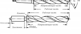
| Fig. 1 - type of surface treatment is not set | Fig. 2 - surface treatment with removal of a layer of material (turning, milling...) | Fig. 3 - surface treatment without removing a layer of material (forging, casting...) |
| The type of surface treatment is indicated only if the specified surface quality cannot be obtained by another type of treatment. | ||
| H=(1.5-3)h, h - approximately equal to the height of the dimensional numbers | ||
Below is a picture showing the roughness direction symbols on the roughness icon. (The administration of the DPVA project has never seen such badges, but they exist).
Drawing. Symbols for directions of irregularities on the roughness icon.
What roughness parameters exist?
There are over 8 parameters that characterize the height of surface irregularities. In this article we will analyze only the most popular ones, ignorance of which will be a significant gap for any technical specialist. These are Ra and Rz. The Rz value shows the arithmetic mean of the height taken over 10 surface points. This means that only 5 rises and 5 troughs were involved in the measurement. The rest of the “mountain range” was not taken into account. In the SI system, Rz is measured in micrometers.
Ra is also the arithmetic mean of the roughness height. What distinguishes it from Rz is that not 10 points are taken into account, but all of them. For this reason, the Ra parameter more accurately reflects the roughness of surfaces and is considered more preferable.
In addition to Ra and Rz, it is worth mentioning one more parameter, similar in meaning to the above. This is Rmax. It displays the height of surface irregularities only at its maximum points. According to the greatest height and smallest depression. Currently, Rmax is not used due to its rough accuracy.
Measurement
Roughness is measured in two ways: qualitative and quantitative. The qualitative method for assessing surface roughness is more suitable directly for production workers. In those situations where a deep analysis is not advisable or there is simply no time for it. This method is more crude in nature and consists of comparing the smoothness of the surface under study with a certain standard to the touch.
The standard is a small metal tile with overall dimensions of 30x30 mm and a thickness of 5 mm. It has a certain Ra and Rz value, and is a standard against which the surface quality is compared. Such slabs are collected in sets with the roughness value indicated opposite each position.
The quantitative method is more accurate and requires special equipment for its implementation. These can be profilometers, profilographs and double microscopes. A rod with a diamond tip, highly sensitive to movements, connected to the instruments, is passed along the surface under study. This rod completely repeats the shape of the surfaces and transfers its dimensions to the screen or profilogram tape. Next, based on the data received, the laboratory technician makes an accurate conclusion about the value of roughness and passes it on to the quality service.
What is base length and what is it used for?
Base length l – the length of the base line used to highlight irregularities, characterizing the surface roughness. The base line is drawn relative to the profile of irregularities in a certain way and has a given geometric shape.
What does Ra mean?
Ra is the symbol for the chemical element radium. Ra - designation of surface roughness (arithmetic mean deviation of the profile in microns)
What is RZ in the drawing?
Rz – height of profile irregularities at ten points. Surface roughness is indicated in the drawing for all product surfaces made according to this drawing, regardless of the methods of their formation, except for surfaces whose roughness is not determined by the design requirements.
What is RZ 20?
The sum of the arithmetic mean absolute deviations of the points of the five largest minima and five largest maxima of the profile within the base length. The distance between the line of profile protrusions and the line of profile depressions within the base length.
What is roughness
Any type of surface, no matter how smooth it may seem at first glance, has a series of rises and depressions in its structure. In appearance it is close to the shape of mountain ranges. The height of these “mountains” is characterized by roughness.
Roughness is a set of surface irregularities.
The parameters, measuring instruments and designation of roughness in the design documentation are completely standardized. They are described by three state standards: GOST 2789-73, GOST 25142-82 and GOST 2.309-73.
Control methods
To control surface roughness, two methods are used:
- qualitative;
- quantitative.
When carrying out qualitative control, a comparative analysis of the surface of the working test and standard samples is carried out by visual inspection and by touch. To carry out the research, special sets of surface samples are produced that have routine processing in accordance with GOST 9378-75. Each sample is marked indicating the Ra index and the method of influencing the surface layer of the material (grinding, turning, milling, etc.). Using visual inspection, it is possible to fairly accurately characterize the surface layer with characteristics Ra = 0.6-0.8 µm and higher.
Surface roughness samples
Quantitative surface control is carried out using instruments using different technologies:
- profilometer;
- profiler;
- double microscope.
Basic rules used to indicate surface roughness in drawings
Basic rules to use when making a drawing:
- The drawing indicates all surface roughness for the material used without taking into account the methods used.
- The application of roughness values is carried out on sections that have a size.
- Signs are applied to all types of lines used in the drawing.
- If a sign has a shelf, its location is determined in relation to the main inscription.
- If the product has a gap in the drawing, then only one part of the image is marked.
- If the surface layer requires the use of processing sections of a part of different classes, then division is made using a solid line.
- In case of reducing the space required for marking on the drawing, an acceptable simplification of the symbols is possible.
- If the contour surface roughness value is the same, the value is applied once.
- If different surfaces with the same roughness values are identical, it is allowed to apply the values once.
- Signs indicating irregularities must be 1.5 times thicker than those printed on the image.
- Conditions indicating the direction of surfaces must comply with the standards.
- The designation of surface roughness is made using general rules.
Designations for the direction of surface roughness in drawings
Taking into account the structure of the material, the designer has the opportunity to specify the necessary parameters for the quality of surfaces. Moreover, the characteristics can be specified according to several parameters, setting the maximum and minimum values with possible tolerances.
Surface structure marking
In the drawings, the roughness designation is made for all surfaces of the product, with the exception of those whose roughness is not indicated by the requirements. In the design documentation, the marking is indicated by a special icon, which has an additional shelf and other clarifications. If the processing method is not indicated, then the icon is shown in the drawing without a shelf.
Rules for applying roughness marks on drawings
Signs to indicate surface roughness depending on the type of processing
Main sign
The main icon that corresponds to the standard condition for normalizing roughness. Used when the method of roughness formation is not regulated.
Mechanical processing
This mark is used when the surface is obtained as a result of mechanical processing. For example, when grinding, turning, polishing, etc. This designation may not indicate a specific type of mechanical effect.
Designation for casting or stamping processing
This designation is used when the surface is obtained without removing the layer by mechanical processing. For example, casting or stamping. It is also not indicated what work was carried out on the part.
Examples of surface roughness designation
In order to understand the designation of surface roughness in drawings, you need to consider a few simple examples:
- √(Ra 3) – the number “3” indicates the highest permissible value of the parameter. Depending on the number, the characteristics will also change; it is logical that if “3” is replaced with “80” or “10”, then during manufacturing the part will achieve the desired value.
- √(Rz 40 min);√(Rz 20min) – Rz 40min and Rz 20min indicate the lowest value of the parameter. This designation is used when, in order to properly perform its functions, the part must not have a too smooth surface.
More detailed information about designations can be found in GOST 2.309-73.
Symbols for directions of surface irregularities
- √(=Ra1) – irregularities are directed parallel to each other.
- √(⊥Ra1) – perpendicular direction.
- √(X Ra1) – directions intersect.
- √(М Ra1) – arbitrary direction.
- √(С Ra1) – circular direction.
- √RRa1 – radial direction relative to the center of the surface.
- √PRa1 – irregularities are directed randomly.
Interesting: Description and types of technological processes
Designations for the direction of surface roughness in drawings
How to choose roughness?
Choosing roughness is not as complicated a process as it might seem. Everywhere I have worked, and my friends do the same, the default roughness is Ra6.3 for all surfaces where there are no specific instructions on the smoothness of the surface. For smoother surfaces, such as polished ones, the roughness value can range from 3.2 to 0.1. You need to look at the target accessory of the part. For example, if a cooled radiator is applied to the surface for which the roughness is indicated, then it must be made smooth - Ra1.6. During all my work, I have seen the use of only four roughness options:
- 6.3 everywhere
- 3.2 in neater places, such as rubber seal grooves
- 1.6 in places of contact of cooled surfaces
- 0.8 in places where the surface was polished (laser technology)
When trying to consider this issue on the Internet, you can find many different pictures with theory, where a tricky part is drawn with all possible types of processing and roughnesses for these types are indicated. It is characteristic that in all these pictures the numbers appear to be the same, but their ranges are different. In any case, for the general concept of correct roughness setting, the list above will be sufficient, but for more tricky details you should study the requirements that apply to them specifically at the enterprise or by the customer.
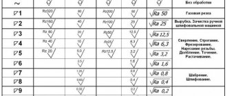
Roughness table
The initial roughness is a consequence of the technological processing of the surface of the material. For a wide class of surfaces, the horizontal pitch of irregularities ranges from 1 to 1000 µm, and the height - from 0.01 to 10 µm. As a result of friction and wear, the parameters of the initial roughness, as a rule, change, and operational roughness is formed. The operational roughness, reproduced under stationary friction conditions, is called equilibrium roughness.
| Class | 1 | 2 | 3 | 4 | 5 | 6 | 7 | 8 | 9 | 10 | 11 | 12 | 13 | 14 |
| The cells above indicate roughness classes for comparison with the new standard | ||||||||||||||
| Ra | 100 | 50 | 25 | 12.5 | 6.3 | 3.2 | 1.6 | 0.8 | 0.4 | 0.2 | 0.1 | 0.08 | 0.025 | 0.01 |
| Rz | 400 | 200 | 100 | 50 | 25 | 12.5 | 6.3 | 3.2 | 1.6 | 0.8 | 0.4 | 0.2 | 0.1 | 0.05 |
| Sandblasting | Rz400 | |||||||||||||
| Forging in dies | Rz400 | Rz200 | Rz100 | |||||||||||
| Sawing | Rz400 | |||||||||||||
| Drilling | Rz100 | Rz50 | Rz25 | |||||||||||
| Rough countersinking | Rz100 | Rz50 | Rz25 | |||||||||||
| Finish countersinking | Rz50 | Rz25 | 3.2 | 1.6 | ||||||||||
| Deployment is normal | 3.2 | 1.6 | 0.8 | |||||||||||
| Deployment is precise | 1.6 | 0.8 | 0.4 | |||||||||||
| Deployment is subtle | 0.8 | 0.4 | 0.2 | |||||||||||
| Reaching out | Rz25 | 3.2 | 1.6 | 0.8 | 0.4 | |||||||||
| Rough turning | Rz400 | Rz200 | Rz100 | Rz50 | ||||||||||
| Finish turning | Rz100 | Rz50 | Rz25 | 3.2 | 1.6 | 0.8 | ||||||||
| Fine turning | 3.2 | 1.6 | 0.8 | 0.4 | ||||||||||
| Preliminary planing | Rz400 | Rz200 | Rz100 | Rz50 | ||||||||||
| Finish planing | Rz100 | Rz50 | Rz25 | 3.2 | 1.6 | |||||||||
| Fine planing | 1.6 | 0.8 | ||||||||||||
| Pre-milling | Rz200 | Rz100 | Rz50 | Rz25 | ||||||||||
| Finish milling | Rz25 | 3.2 | 1.6 | |||||||||||
| Milling fine | 3.2 | 1.6 | 0.8 | |||||||||||
| Pre-grinding | Rz25 | 3.2 | 1.6 | |||||||||||
| Finish grinding | 1.6 | 0.8 | 0.4 | |||||||||||
| Sanding fine | 0.4 | 0.2 | ||||||||||||
| Sanding - finishing | 0.1 | 0.08 | Rz0.1 | Rz0.05 | ||||||||||
| Rough grinding | 0.8 | 0.4 | ||||||||||||
| Lapping average | 0.4 | 0.2 | 0.1 | |||||||||||
| Fine lapping | 0.1 | 0.08 | Rz0.1 | Rz0.05 | ||||||||||
| Honing is normal | 1.6 | 0.8 | 0.4 | 0.2 | ||||||||||
| Mirror honing | 0.4 | 0.2 | 0.1 | 0.08 | ||||||||||
| Scraping | 3.2 | 1.6 | 0.8 | |||||||||||
| Rolling | Rz50 | Rz25 | 3.2 | 1.6 | 0.8 | |||||||||
| Chill casting | Rz400 | Rz200 | Rz100 | Rz50 | ||||||||||
| Injection molding | Rz400 | Rz200 | Rz100 | Rz50 | Rz25 | 3.2 | ||||||||
| Precision casting | Rz50 | Rz25 | 3.2 | 1.6 | ||||||||||
| Plastic molding, precision | Rz25 | 3.2 | 1.6 | 0.8 | 0.4 | 0.2 | 0.1 |
Special conditions
During mass production of certain parts, the specified shape or their conjugation is sometimes violated. Such violations increase the permissible wear of parts, and are limited by special tolerances, which are specified in GOST 2.308-2011. Each type of tolerance used has 16 defining degrees of accuracy, which are specified for parts of different configurations, taking into account the material used. It is also necessary to take into account that the size and configuration tolerances used for parts with a cylindrical shape are taken taking into account the diameter of the parts, and for flat parts taking into account the thickness, and the maximum error should not exceed the tolerance value.
Sources
- https://vt-metall.ru/articles/436-klassy-chistoty-obrabotki-metalla
- https://engineerscreed.ru/sherohovatost-poverhnosti/
- https://morflot.su/sherohovatost-poverhnosti-ra-i-rz-otlichie/
- https://osntm.ru/scherochowatost.html
- https://lfirmal.com/sherohovatost-poverhnosti-4/
- https://crast.ru/instrumenty/sherohovatost-ra-i-rz-v-chem-raznica
- https://vologda-yel.ru/chto-oznachaet-znak-sherohovatosti-v-skobkah/
- https://sakhkor.ru/tehnologii/tablica-sherohovatosti-poverhnosti.html