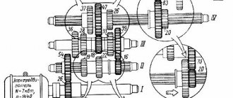
14.1. Design and geometric parameters of a twist drill
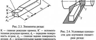
The following parts are distinguished in a twist drill (Fig. 14.2).
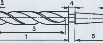
Working part
– part of the drill equipped with two spiral (more precisely, helical) grooves; the working part includes the cutting and guiding parts of the drill.
Cutting part
- part of the drill, sharpened to a cone and bearing the cutting edges.
Guide part
– part of the drill that provides direction for the drill during the cutting process.
Shank
- part of the drill that serves to secure it and transmit torque from the spindle.
Paw
(for drills with a conical shank) serves as a stop when knocking the drill out of the spindle hole.
Rice. 14.2. Drill components
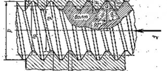
The main elements of a twist drill (Fig. 14.3).
Front surface
1
is the helical surface of the groove along which chips flow.
Main back surface 2
– surface facing the cutting surface.
Auxiliary rear surface (ribbon)
3
– a narrow strip on the cylindrical surface of the drill, located along the helical groove; Provides direction to the drill when cutting.
Main cutting edge 4
– an edge formed by the intersection of the front and main rear surfaces.
Secondary cutting edge 5
– an edge formed by the intersection of the front and auxiliary rear surfaces.
Cross edge 6
– formed at the intersection of two main rear surfaces.
Blade top 7
– the intersection point of the main and auxiliary cutting edges.
Drill back 8
– a surface lowered relative to the ribbon, designed to reduce friction between the drill and the machined surface of the hole.
Rice. 14.3. Drill blade surfaces and cutting edges
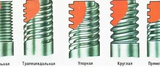
The two main cutting edges (see Fig. 14.2), located on the cutting part (fence cone), form an apex angle of 2φ, which for drills made of tool steels when processing structural materials is usually equal to 116...118°; for different materials it should be different: for harder ones - more, for softer ones - less. For example, when processing heat-resistant and stainless materials, drills with an angle of 2φ = 125...135° (for a blind hole) and 2φ = 140° (for through holes) have maximum durability; when processing ebonite, marble and other fragile materials, the angle 2φ = 80...90°; when drilling titanium alloys 2φ = 90…120°; when drilling aluminum and aluminum alloys 2φ = 130…140°.
Cross edge angle
ψ is measured between the projections of the transverse and main cutting edges onto a plane perpendicular to the drill axis; with proper sharpening of the drill, the angle ψ = 50...55°.
The inclination of the helical groove along which the chips flow is determined by the angle ω between the axis of the drill and the tangent to the helical line along the outer diameter of the drill. This angle ω, called the helical groove angle
drill, determines the value of the rake angle: with increasing angle ω, the rake angle increases and thereby facilitates the chip formation process. The inclination of the screw groove of drills is taken from 18 to 30°. As the angle ω increases, the strength of the drill decreases, as a result of which it becomes smaller for small-diameter drills than for large-diameter drills.
Geometric parameters of the cutting part of the drill.
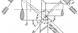
The angles of the cutting edges of the drill are considered in a static state and during the cutting process (in motion). Let's consider a drill as a geometric body in a static coordinate system.
Static coordinate system
– a rectangular coordinate system with the origin at the considered point of the cutting edge, oriented relative to the direction of the speed of the main cutting movement (Fig. 14.4,
a
).
The main plane
P V is
a coordinate plane drawn through the point of interest on the cutting edge perpendicular to the direction of the speed of the main cutting movement at this point.
Cutting plane
P n is
a coordinate plane tangent to the cutting edge at the point under consideration and perpendicular to the main plane
P V
.
The main cutting plane
P
τ
is
a coordinate plane perpendicular to the intersection of the main plane and the cutting plane.
Working plane Р s –
the plane in which the directions of the velocities
V
and
V s
of the main cutting movement
D r
and the feed movement
D s
.
Rice. 14.6. Static drill angles in the main secant and working planes for various points of the cutting edge
Main rake angle
γ is the angle in the main secant plane
P
τ
– P
τ between the front surface
A
γ of the blade and the main plane
P V – V
.
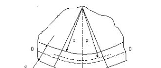
The rake angle of the drill at an arbitrary point x
of the cutting edge is clearly shown in Fig.
14.7. The front angles γ and γ s
in the main cutting plane
P
τ
– P
τ and the working plane
P s – P s
are determined as follows.
In Fig. Figure 14.8 shows the development of helical lines lying on cylinders with diameters D
,
D
1,
D
2. From Fig. 14.8 it can be seen that the front angles in the working plane for the points under consideration will be equal:
,
,
.
Rice. 14.7. Rake angle measurement diagram
For an arbitrary point of the cutting edge lying on the diameter D x ,
will have
,
where H
– pitch of the helical flute of the drill, mm.
Since at any point X
cutting edge, the pitch of the drill helix
H
remains constant, then we can write
.
In the main cutting plane P
τ
– P
τ rake angle is determined by recalculation using the formula
.
The final recalculation formula has the form
.
Source
Drill bits with tapered shanks
Modern industry produces various types of drills, the shank of which has a conical shape. Accordingly, the requirements for such tools are regulated by different GOSTs. The unification of various types of drills allows them to be optimally selected for solving specific technological problems. The regulatory documents in accordance with the requirements of which spiral tools with tapered shanks are produced are:
- GOST 10903-77 (for products of normal length);
- GOST 12121-77 (for long series);
- GOST 2092-77 (for extended series);
- GOST 22736-77 (for products with carbide plates).
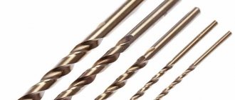
Metal drills with tapered shank for deep drilling
You can familiarize yourself with the GOST requirements for twist drills with a tapered shank by downloading the document in pdf format from the link below.
Twist drills of normal length, which are subject to the requirements of GOST 10903-77, can be produced in the diameter range of 5–80 mm. The shanks of such drills, depending on the diameter of the latter, have a normal or reinforced design. Spiral drills with a diameter of 12 to 76 mm are made with a reinforced shank. Their landing cone part corresponds to the Morse standard - from 1 to 6.
The diameter of long drills, according to GOST, can be in the range of 5–20 mm, while the processing performed with their help is carried out through jig bushings. The shank of such drills is made according to the Morse standard from 1 to 4. The spiral part of long drills and tools of normal length has a right direction, but by agreement with the manufacturer it can also be produced with a left direction.
Morse tapers with foot
Long drills with a tapered shank are produced with diameters of 6–30 mm. The tapered shank of such drills must comply with the Morse standard from 1 to 3.
Drills with a conical shank, on the metal rod of which carbide inserts of the VK type are soldered, can be produced with a diameter of 10 to 30 mm, in shortened and normal versions.
The lengths of the spiral tools with tapered shank of all series are shown in the table below.
Table 3. Taper Shank Twist Drill Lengths
The manufacturing materials for the main part of such drills are high-speed steel, steel alloy grade 9ХС or steel of other grades, which should not contain cobalt, and the amount of tungsten should not exceed 6%.
And in conclusion, a short video review of metal drills from various manufacturers with testing of these products in practice.
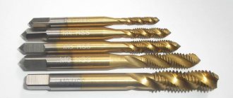
Twist Drill Geometry
Drilling is one of the most common methods for making a hole. The cutting tool is a drill, which is used to make a hole in a solid material or increase the diameter of a previously drilled hole (reaming). The cutting movement during drilling is rotational, the feed movement is translational. The cutting part of the drill is made of tool steels (P18, P12, P6M5, etc.) and hard alloys. According to their design, drills are distinguished: spiral, with straight flutes, feather, for deep holes, for annular drilling, centering and special combined. Structural elements include: drill diameter D
, angle of the cutting part (apex angle), angle of inclination of the helical groove w, geometric parameters of the cutting part of the drill, i.e.
respectively, front g and rear a angles and cutting angle d, core thickness d
(or core diameter), feather (tooth) thickness
b
, ribbon width
f
, reverse taper j1, cutting edge shape and drill groove profile, working part length
l
o, total drill
length L.
Drills with cylindrical shanks
Twist drills with a cylindrical shank, in accordance with the requirements of the regulatory document, can be produced in several series: short, medium and long. Using the appropriate GOST for drills, you can optimally select the tool to solve certain technological problems.
Cylindrical spiral drills, according to GOST, are manufactured with or without a centering hole. Tools of medium and long series, in accordance with GOST, may have a neck in their design, which facilitates their grinding. There are no special requirements for the size of such an element.
You can familiarize yourself with the GOST requirements for twist drills with a cylindrical shank by downloading the document in pdf format from the link below.
Metal drills with cylindrical shank
Left and right spiral instruments belonging to the short series and having a diameter from 0.5 to 40 mm are manufactured in accordance with GOST 4010-77. The production of right and left cylindrical drills of the middle series, the diameter of which is in the range of 0.25–20 mm, is regulated by GOST 10902-77. Long series twist drills are available in the diameter range 1–31.5 mm. The regulatory document that specifies the requirements for products in this series is GOST 886-77.
Drills with a cylindrical shank of a long series are produced mainly with a right-handed spiral direction. GOST allows the manufacture of products of this series in another design by agreement with the customer. The lengths of cylindrical shank spiral tools of all series are shown in the table below.
Table 2. Straight Shank Twist Drill Lengths
Technical requirements for the production of twist drills of all the above series are specified by GOST 2034-80. According to the provisions of this regulatory document, products of this series, which are used for drilling workpieces made of malleable and gray cast iron, carbon (structural and tool) and alloy steels, as well as structural steels of ordinary machinability and automatic machine, are made of high-speed steel alloys. Instruments in this series can belong to one of three accuracy classes:
- A1 (increased);
- B1 and B (normal).
Cylindrical shanks can have different designs
GOST allows that drills of this series can be made not from high-speed steel, but from alloy steel alloy grade 9ХС, while their shanks can be made from steel grade 45 or 40Х. According to their design, such drills can be either solid or welded. When using welding at joints, the presence of unwelded areas, voids and ring cracks is eliminated.