Geometric parameters and sharpening of the cutting part of tools
Home » Articles » Professionally about metalworking » Metal cuttingWe recommend purchasing:
Installations for automatic welding of longitudinal seams of shells - in stock!
High performance, convenience, ease of operation and reliability in operation.
Welding screens and protective curtains are in stock!
Radiation protection when welding and cutting. Big choice. Delivery throughout Russia!
Turning cutters (Fig. 2.3) are the most common cutting tools. They, like metal-cutting tools of all other types, have a connecting part (section l2) in the form of a holder or body, as well as a cutting part (section 1, with the help of which the process of cutting chips is carried out. The cutting part consists of one or more structurally separate cutting elements (teeth) that work simultaneously or sequentially, continuously or intermittently, entering into work one after another.
Each cutting element has a front blade surface Aγ (along which chips flow), which contacts the cut layer during the cutting process, and one or more rear blade surfaces Aα. One of the cutting surfaces is called the main one, and the rest are called the auxiliary rear surfaces of the blade. The rear surfaces of the blade face the workpiece being processed.
The main cutting edge K, which performs the main cutting work, is formed at the intersection of the front and rear surfaces of the tool blade. The apex of the blade is the section of the cutting edge at the intersection of the two rear surfaces (main and auxiliary). The radius of curvature of the tip of the blade rв is called the tip radius.
The cutting edges and the adjacent front and rear surfaces of the blade together form the main and auxiliary blades. Overcoming the resistance of the material being processed, the blades cut into the workpiece and remove chips from it. The blades of all tools in cross section have the shape of a wedge, which is limited on one side by the front surface and on the other by the rear surface (see Fig. 2.1).
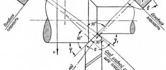
To determine the angles of the cutter blade or the cutting element of other tools, the following concepts are established: cutting plane and main plane (GOST 25762-83). The cutting plane is a plane tangent to the cutting edge at the point under consideration and perpendicular to the main plane (Fig. 2.4).
The main plane is a plane drawn through a point on the cutting edge perpendicular to the direction of the speed of the main or resulting cutting movement at this point.
There are main and auxiliary angles of the blade (Fig. 2.5). Principal angles are measured in the principal cutting plane, i.e., the plane perpendicular to the projection of the principal cutting edge onto the principal plane.
The main rear cutting angle α is the angle located in the secant plane between the rear surface of the blade and the cutting plane.
The blade sharpening angle β is the angle in the secant plane between the front and rear surfaces of the blade.
The main rake angle of the blade γ is the angle located in the secant plane between the front surface of the blade and the main plane. Sum of angles α + β + γ = 90°.
The main angle φ is the angle in the main plane located between the cutting plane and the working plane, in which the speed directions of the main cutting movement and the feed movement are located.
The inclination angle of the main cutting edge λ is the angle in the cutting plane between the cutting edge and the main plane.
Giving the cutting part of the tool the specified geometric parameters and restoring the cutting properties of the tool, lost as a result of its wear and dullness, is carried out by sharpening and finishing.
High-quality and timely sharpening and finishing of a tool allows not only to restore its geometric parameters, but also helps to improve the quality of processed parts, increase the productivity of machine workers in the main production, reduces tool consumption, and contributes to the rhythmic and uninterrupted operation of metal-cutting machines.
For example, if you refine the main elements of the cutting part of a high-speed steel cutter, then with the same period of its service life you can increase the cutting speed by 10 ... 15%. If the cutting speed is left within the same limits, then the durability of the finished high-speed cutter will almost double, which will reduce tool costs and reduce the auxiliary time associated with changing tools and readjusting the machine.
Consequently, the process of sharpening and finishing a cutting tool has the following main purpose:
- manufacturing the cutting part of the tool with optimal specified geometric parameters that help increase tool life, accuracy and processing performance;
- ensuring the specified roughness of sharpened or finished tool surfaces, guaranteeing the quality of the machined surface and reducing tool wear;
- preservation of the cutting properties inherent in the tool material due to the minimum permissible changes in the surface layers of the tool associated with structural transformations, the appearance of internal stresses and cracks; increasing tool life;
- meeting the conditions for economical operation of the tool.
Tool sharpening is carried out at machine-building enterprises, usually centrally. At the same time, having a certain qualification, the machine operator periodically performs this operation himself. For example, you can sharpen cutters and drills by hand. To sharpen more complex tools, special equipment is required.
Educational materials
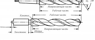
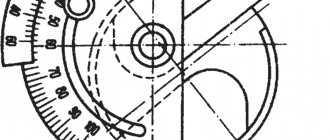
A turning cutter has a head - working part I and a body-rod II (Figure 4.2), which serves to secure the cutter in the tool holder.
The cutter head is formed during sharpening and has the following surfaces: front surface 1 (chips come off); main rear surface 2 (facing the cutting surface of the workpiece); main cutting edge 3 and auxiliary 6; top 4 (rounded or cut to increase wear resistance).
Figure 4.2 – Elements of a turning straight cutter
The tool is sharpened along the front and back surfaces. The cutter angles determine the relative position of the surfaces of the working part of the tool, as well as the sharpness of the cutting wedge and the cross-sectional shape of the cut layer. Angles are considered based on the following conditions: the axis of the cutter must be perpendicular to the line of the centers of the machine; the tip of the cutter is on the line of the centers of the machine; the main cutting movement occurs.
Tool angles have a significant impact on the cutting process and processing quality (Figure 4.3).
Rake angle γ
has a great influence on the cutting process. With an increase in +γ, the deformation of the cut layer decreases, since the tool cuts into the material more easily, cutting forces and power consumption are reduced. At the same time, the conditions for chip flow improve, and the quality of the machined surface of the workpiece increases. However, an excessive increase in +γ leads to a decrease in the strength of the main cutting edge, an increase in the contribution due to chipping, and a deterioration in the conditions for heat removal from the cutting edge.
When processing parts made of brittle and hard materials, to increase the durability of the cutter, smaller values of the angle +γ, sometimes even negative, should be assigned. When processing parts made of soft and viscous materials, the rake angle +γ is increased γopt = +18 ÷ -4° (-10°).
Figure 4.3 – Geometric parameters of a through turning cutter
Main clearance angle α
– the presence of α reduces friction between the main flank surface of the tool and the cutting surface of the workpiece, which reduces tool wear along the main flank surface. For soft and viscous materials, α should be greater than when processing hard and brittle materials. Typically αopt = 6 ÷ 12°.
Principal angle φ
– has a significant effect on the roughness of the machined surface.
As the angle φ decreases, the roughness of the machined surface decreases. At the same time, the active working length of the main cutting edge increases; Accordingly, the cutting force and cutting temperature per unit edge length are reduced, which reduces tool wear.
However, as the angle φ decreases, the cutting force directed perpendicular to the workpiece axis Ru increases, therefore the deformation of the workpiece and the pressing of the cutter from the workpiece increases: φ = 30 ÷ 90°. When φ = 90° – a through cutter for processing a conical surface. Thus, as the angle φ decreases, vibrations may occur during the cutting process, reducing the quality of the machined surface.
As the angle φ1 decreases, the roughness of the machined surface decreases, the strength of the cutter tip increases and its wear decreases.
Angle of inclination of the main cutting edge λ
negative when the cutter tip is the highest point: usually λ = 0...4°. In this case, the chips fall onto the machined surface in front of the cutter (the cutter is less durable) and is recommended for finishing operations.
When the tip of the cutter is the lowest point, λ is positive (the head is more massive, therefore stronger). In this case, the chips move towards the machined surface, scratch the machined surface and prevent the worker from monitoring the processing, but at the same time the cutter head is massive and resistant, recommended for roughing work and when processing discontinuous surfaces.
The marked angles are static angles. Angles g, α, φ may change due to the installation error of the cutter:
- if, when turning, the top of the cutter is above the line of centers, then the angle +g increases and the angle α decreases, and when setting the top of the cutter below the line of centers, vice versa;
- if the cutter axis is not perpendicular to the center line, this will cause a change in the angles φ and φ1.
Since in fact the cutting surface to which the cutting plane is tangent is a helical surface during the cutting process the angles γ and α => var.
When working with Smax and threading, the change in angles g and α will be significant, which must be taken into account when manufacturing cutters.
Processing of workpieces on lathes > Theory according to TCM >
Tool parameters according to ISO 13399 Cutting tool data
Standardized parameters of cutting tools and machining processes on machine tools according to ISO 13399 Part 1
Standardized parameters for cutting tools and machining processes on machine tools according to ISO 13399 Part 1 _ General information ISO 13399 New standard - to make life easier B ISO 13399 is an international standard for simplifying the exchange of data on cutting tools. The standard defines new parameters and descriptions for each tool. For the first time, there was a standardized way to describe cutting tool data. If the same parameters and definitions are used to designate all tools, the process of transferring tool data between different software systems will be greatly simplified. C What does this mean for you Essentially, this means that your systems will be able to communicate with our systems, since they will all speak the same language. Download product data from our website and apply it to your CAD/CAM system to assemble tool setup for your production. You don't have to search for information in catalogs and transfer data from one system to another. Imagine how much time you can save Symbol Description ADJLN Minimum adjustment amount ADJLX Maximum adjustment amount ADJRG Adjustment range ALP Axial relief angle AN Main relief angle ANN Auxiliary relief angle APMX Maximum depth of cut B Shank width BAWS Body angle workpiece side BAMS Body angle side machine BBD Structurally balanced BBR Individually balanced bch Chamfer nose length bd Body diameter BHTA Half taper angle BN Chamfer width BS Wiper edge length BSG Standard BSR Wiper edge radius cbmd Chipbreaker manufacturer cdx Maximum depth of cut cf Chamfer CHBA Body chamfer angle chbl Body chamfer length chw Chamfer width at tip chwl Chamfer width at tip, left chwr Chamfer width at tip, right cict Number of cutting elements cnd Coolant hole diameter cnsc Type of coolant supply to tool cnt Coolant inlet thread size COATING Finish CP Maximum coolant pressure crks Thread size center bolt crnt Thread size of the hole for radial coolant supply ctpt Operation type cutdia Maximum cut-off diameter of the workpiece cw Cutting width cwn Minimum cutting width cwtoll Lower cutting width deviation cwtolu Upper cutting width deviation cwx Maximum cutting width cxsc Type of coolant supply to the cutting zone czc Connection size CZCms Machine side connection size CZCws Workpiece side connection size D1 Screw hole diameter dah Screw head hole diameter daxin Minimum internal diameter of face groove daxn Minimum external diameter of face groove H 36 SANDVIK international