How is surface roughness measured?
Surface roughness is measured in micrometers (1 µm = 0.001 mm) and is usually assessed using two parameters Rz and Ra .
Rz is the height of profile irregularities at 10 points while Ra is the arithmetic mean deviation of the profile.
For an approximate correspondence of these parameters to each other with reference to the class of surface roughness cleanliness, see the table below:
| Surface cleanliness class | Arithmetic mean profile deviation Ra, µm | Roughness height Rz, µm | Base length l, mm |
| no more | |||
| 1 | 80 | 320 | 8 |
| 2 | 40 | 160 | 8 |
| 3 | 20 | 80 | 8 |
| 4 | 10 | 40 | 2,5 |
| 5 | 5 | 20 | 2,5 |
| 6 | 2,5 | 10 | 0,8 |
| 7 | 1,25 | 6,3 | 0,8 |
| 8 | 0,63 | 3,2 | 0,8 |
| 9 | 0,32 | 1,6 | 0,25 |
| 10 | 0,16 | 0,8 | 0,25 |
| 11 | 0,08 | 0,4 | 0,25 |
| 12 | 0,04 | 0,2 | 0,25 |
| 13 | 0,02 | 0,1 | 0,08 |
| 14 | 0,01 | 0,05 | 0,08 |
Role and significance
Roughness plays an important role in determining how a real object will interact with its environment. In tribology, rough surfaces typically wear faster and have higher coefficients of friction than smooth surfaces. Roughness is often a good predictor of mechanical component performance, since surface irregularities can provide nucleation points for cracks or corrosion. On the other hand, roughness can promote adhesion. Generally speaking, instead of scale descriptors, cross-scale descriptors such as surface fractality provide more meaningful predictions of mechanical interactions at surfaces, including contact stiffness and static friction. Surface roughness is a rather complex parameter, details of which can be found below.
Channel PROGRAMMER'S DIARY
The life of a programmer and interesting reviews of everything. Subscribe so you don't miss new videos.
Surface Roughness Measuring Tools
Surface roughness can be measured in two ways:
- Visual method of comparing a surface with a standard (comparison by touch)
- Roughness measuring device
For express assessments in the engineering, repair and instrument-making industries, where deviations from the design value are allowed, as a rule, a visual comparison method is used. Roughness samples obtained by various processing methods and having a previously known roughness value are used as standards.
To more accurately measure surface roughness, in places where strict compliance with design values is required, special instruments are used: profilometers or profilographs. With the help of a profilograph, a so-called profilogram is obtained, which requires additional decoding, while the profilometer immediately shows the exact value of the unevenness according to the specified parameters. There are both portable profilometers used in “field” conditions, and stationary devices that are used in metrology laboratories for direct calibration of roughness standards, as well as for educational purposes.
Based on the above, we can conclude that surface control is important to carry out in cases where wear resistance, anti-corrosion resistance are required and to exclude the possibility of surface cracks from metal fatigue. Sometimes a low level of roughness is needed not only for the technical characteristics of the part, but also for its aesthetic appearance.
Applicable control methods
Surface roughness can be assessed by a variety of methods. Control can be carried out at various stages, in some cases it is visual, in others it involves the use of special tools. The most common methods for controlling surface roughness are:
- Comparators.
- Electronic devices.
- Microscopes.
- Replica method according to ISO standards.
- Profilometer.
Profilometer Mahr Marsurf PS1
comparator CA507 + CA3600A
Surface roughness is controlled during material processing or after production to determine its quality. The most accessible assessment method is visual, but it does not allow determining surface roughness with high accuracy. The visual method is not a type of inspection, but only allows you to determine the presence or absence of defects. The most accessible method for monitoring surface roughness is the use of ISO comparators, the technical indicators of which correspond to the established ISO 8503-1 standard. For control, two types of measuring instruments in question can be used, which are applicable in various industries.
The concept of metal surface quality after processing
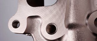
After processing on a milling machine, as after other work with the workpiece, irregularities are formed on its surface - ridges and depressions (in other words, roughness and waviness). Residual stress also appears in the upper layers of the material; at some rolling depths, a difference in hardness appears, which manifests itself as hardening or hardening. Such changes affect the properties of finished products and, consequently, the quality of their surfaces. All these characteristics determine the class of metal processing.
The quality of finished parts is determined by both their physical and geometric characteristics.
- Physical quality criteria.
The surface quality of a product is determined by the relationship between the physical and mechanical properties of its central part and its outer part.
During the processing of metal workpieces, their surface is subject to plastic changes, therefore other characteristics of the material in the finished product differ from the original ones. At the same time, the outer part of the plate is strengthened and internal stresses appear in it.
After the final stage of metal processing on a milling machine, the hardened layer extends only a few hundredths of a millimeter, while after the initial impact of a cylindrical cutter its thickness averages 0.04–0.08 mm, reaching 0.12 mm. When exposed to an end mill, the parameter is 0.06–0.1 mm, although it can be 0.2 mm. The resulting internal stresses and surface hardening lower the class of metal processing by reducing the fatigue strength of the product. Such deformations shorten the service life of the part, which leads to the need for its immediate replacement.
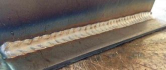
During rough rough processing with a gear cutter at high speeds and with an increased depth of section, irregularities remain on the edge of the product, which are noticeable to the naked eye and are easily determined by touch. Roughness and waviness formed during intermediate and finishing machining at low speeds and during shallow cutting are visually invisible and can barely be felt.
The class of geometric accuracy of metal processing depends on the presence of irregularities on the surface of the product: depressions, ridges, roughness, etc. Such defects on a small surface area are called its microgeometry.
The microgeometry of the surface when processing rolled products depends on:
- cutter geometry, its quality and degree of wear;
- vibrations arising due to insufficient rigidity of the machine or its working elements;
- established settings for the operation of the milling machine (cutting speed and depth, feed per tooth, cooling);
- mechanical properties of the processed sheet and the cutter itself.
Basic rules used to indicate surface roughness in drawings
Basic rules to use when making a drawing:
- The drawing indicates all surface roughness for the material used without taking into account the methods used.
- The application of roughness values is carried out on sections that have a size.
- Signs are applied to all types of lines used in the drawing.
- If a sign has a shelf, its location is determined in relation to the main inscription.
- If the product has a gap in the drawing, then only one part of the image is marked.
- If the surface layer requires the use of processing sections of a part of different classes, then division is made using a solid line.
- In case of reducing the space required for marking on the drawing, an acceptable simplification of the symbols is possible.
- If the contour surface roughness value is the same, the value is applied once.
- If different surfaces with the same roughness values are identical, it is allowed to apply the values once.
- Signs indicating irregularities must be 1.5 times thicker than those printed on the image.
- Conditions indicating the direction of surfaces must comply with the standards.
- The designation of surface roughness is made using general rules.
Designations for the direction of surface roughness in drawings
Taking into account the structure of the material, the designer has the opportunity to specify the necessary parameters for the quality of surfaces. Moreover, the characteristics can be specified according to several parameters, setting the maximum and minimum values with possible tolerances.
Special conditions
During mass production of certain parts, the specified shape or their conjugation is sometimes violated. Such violations increase the permissible wear of parts, and are limited by special tolerances, which are specified in GOST 2.308-2011. Each type of tolerance used has 16 defining degrees of accuracy, which are specified for parts of different configurations, taking into account the material used. It is also necessary to take into account that the size and configuration tolerances used for parts with a cylindrical shape are taken taking into account the diameter of the parts, and for flat parts taking into account the thickness, and the maximum error should not exceed the tolerance value.
Sources
- https://vt-metall.ru/articles/436-klassy-chistoty-obrabotki-metalla
- https://engineerscreed.ru/sherohovatost-poverhnosti/
- https://morflot.su/sherohovatost-poverhnosti-ra-i-rz-otlichie/
- https://osntm.ru/scherochowatost.html
- https://lfirmal.com/sherohovatost-poverhnosti-4/
- https://crast.ru/instrumenty/sherohovatost-ra-i-rz-v-chem-raznica
- https://vologda-yel.ru/chto-oznachaet-znak-sherohovatosti-v-skobkah/
- https://sakhkor.ru/tehnologii/tablica-sherohovatosti-poverhnosti.html
But let's look at these devices in more detail:
1) Profilometer
- a device that is intended for measuring roughness using the contact method. The contact method means that a special diamond needle moves along the surface under study, oscillating due to surface irregularities. Such vibrations of the needle are transmitted to the sensor, where they are converted into small electrical currents, which, in turn, are amplified by a galvanometer and recorded. The readings are displayed on the device display and give an idea of the nature of the unevenness of the surface under study - their height and depth. Often, to assess roughness, other parameters are selected - weighted average, amplitude, total and divided by the length of the surface.
Let's try to briefly describe how a profilometer works, what it consists of, and what the principle of its operation is based on.
So, as in any measuring device, a profilometer must have a measurement object, a measuring signal source (signal generator), a signal processing unit and a unit for outputting measurement results. The object, in this case, is the surface whose roughness needs to be measured. A finely sharpened needle is used as a signal generator, most often a diamond one, but there are profilometers with needles made of hard alloys. The needle moves along the surface, perpendicular to its plane, and on a rough surface, vibrations of the needle inevitably occur. Such mechanical vibrations are the primary signal, which is converted into a current signal using a converter - inductive, capacitive or piezoelectric. After this, the electrical signal is sent to an electronic amplifier, after which it is integrated and visualized. Thus, on the display you can see an already averaged parameter that characterizes not only quantitative, but also qualitative indicators of surface unevenness and roughness.
Profilometers are usually distinguished depending on the type of integration trace.
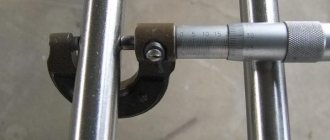
This is interesting: Measurements with calipers - threaded connections, tire treads, linear dimensions
The influence of roughness on the performance of parts
As mentioned earlier, in the process of giving a metal sheet the desired configuration, roughness remains at the impact sites - small depressions and ridges that affect the determination of the metal processing class. They can arise due to the unevenness of the cutting tool or vibrations that occur during work, remain as an imprint of unevenness on the stamp or mold itself, etc.
The presence of roughness in a part installed in a machine or other unit can lead to:
- incorrect mating of elements due to crushing of the material or accelerated wear of the protrusions of the part;
- decrease in joint strength, defects when applying paint and varnish and galvanic coatings;
- incorrect results of geometric measurements of an element;
- reducing the rigidity of butt joints;
- destruction of seals mated to shaft surfaces;
- reducing the fatigue strength of the element due to stress concentration in roughness;
- accelerated oxidation and deterioration of metal, etc.
Contact devices
The schematic diagram of a contact profilometer with inductive signal conversion includes:
- Diamond tip stylus.
- Converter.
- Mechanism for moving the probe.
- Electrical signal amplifier.
- Analog-to-digital converter.
- Display or dial indicator.
- Feedback sensors that control the movement of the probe.
- Time relay.
- Measuring range switch.
A typical representative of this class of measuring equipment is the model 296 profilometer, which can be used to measure the roughness of flat surfaces. The main technical characteristics of the device are given below:
SJ-210 Surfest.
- Measuring range of roughness, microns – 0.02…10.0;
- Number of working assessment ranges – 3;
- Systematic error, % - 2;
- Step parameter, mm – 0.004…2.5;
- Result tracking speed, mm/s – 1;
- Power supply: AC mains.
Meter type 296 and similar ones (for example, model 130) due to their large dimensions make it possible to determine the roughness of products in workshop laboratories.
A portable type profilometer that works on the same principle is the Russian device model TR-100, which includes a piezoelectric transducer. It allows control of roughness if the part has not only flat, but also convex/concave surfaces. Calibration of readings to ensure the device is ready for operation is carried out by a unit built into the main circuit. TR-100 has an increased range (0.05...50 microns), but with the same performance values it has a slightly lower accuracy - ±12%.
Mechanism of roughness occurrence
All causes of roughness can be divided into 3 groups:
- The location of the cutting edges of the tool relative to the surface being processed;
- Elastic and plastic deformation of the processed metal;
- Vibrations in the technological machine system.
The formation of irregularities on the machined surface can be represented as a trace from the movement of the cutting edges of the tool. Let's call this profile regular.
The formation of a regular profile is influenced by the geometry of the cutter, in particular, the angles in the plan, as well as the feed value S. Their influence is described by the formula
In the actual cutting process, a zone of plastic deformation is formed in front of the cutter and under the machined surface, which introduces some error into the regular profile. Plastically deformed metal in some places seems to be enveloping micro-irregularities, and in some places individual pieces of metal are torn out. Therefore, the real value of Rz can be written as:
where is the increment in the height of microroughnesses caused by plastic deformation of the metal. Consequently, the lower the plastic deformation, the lower the height of the microroughnesses. The amount of plastic deformation depends, to a greater extent, on the hardness of the material being processed and, to a lesser extent, on the cutting depth - t.
Mechanics
You may be interested in: The Vendée rebellion and its significance in the history of France
Surface structure plays a key role in controlling contact mechanics, that is, the mechanical behavior exhibited at the interface between two solid objects as they approach each other and transition from non-contact to full contact conditions. In particular, normal contact stiffness is determined primarily by roughness structures (surface slope and fractality) and material properties.
From an engineering surfaces perspective, roughness is considered detrimental to part performance. As a consequence, most production prints set an upper limit on roughness, but not a lower limit. The exception is cylinder bores, where oil is retained in the surface profile and a minimum surface roughness (Rz) is required.
Basic rules used to indicate surface roughness in drawings
Basic rules to use when making a drawing:
- The drawing indicates all surface roughness for the material used without taking into account the methods used.
- The application of roughness values is carried out on sections that have a size.
- Signs are applied to all types of lines used in the drawing.
- If a sign has a shelf, its location is determined in relation to the main inscription.
- If the product has a gap in the drawing, then only one part of the image is marked.
- If the surface layer requires the use of processing sections of a part of different classes, then division is made using a solid line.
- In case of reducing the space required for marking on the drawing, an acceptable simplification of the symbols is possible.
- If the contour surface roughness value is the same, the value is applied once.
- If different surfaces with the same roughness values are identical, it is allowed to apply the values once.
- Signs indicating irregularities must be 1.5 times thicker than those printed on the image.
- Conditions indicating the direction of surfaces must comply with the standards.
- The designation of surface roughness is made using general rules.
Designations for the direction of surface roughness in drawings
Taking into account the structure of the material, the designer has the opportunity to specify the necessary parameters for the quality of surfaces. Moreover, the characteristics can be specified according to several parameters, setting the maximum and minimum values with possible tolerances.
Designations for deviation of surface roughness
In the drawing, the roughness is indicated according to the diagram below.
As you can see, the external designation resembles a mathematical square root with corresponding inscriptions in certain places. Each such inscription characterizes a certain roughness parameter. Let's look at them in more detail.
In the upper left corner the roughness value for Ra and Rz is indicated. It is worth noting that if a simple number is shown, then this automatically means Ra. To designate Rz, you must additionally add a letter note.
There are three variations in the form of this mathematical root:
A triangle without an upper base indicates that the method of obtaining roughness is not specified by the designer
There are requirements for surface quality, but it doesn’t matter how it will be achieved (scraping, polishing, etc.). With a circle at the top. The surface does not need additional improvement. With underscore
This sign says that roughness must be achieved by mandatory removal of a layer of metal.
In the area above the shelf, the type of mechanical treatment is prescribed with which it is necessary to bring the surface to the specified Ra and Rz values. Usually terms such as “polishing”, “scraping” and other types of mechanical processing are prescribed here.
In the lower left corner under the shelf the direction of the roughness lines is written. Let's look at this parameter using an example. Suppose you need to sand the surface of the table with an abrasive wheel. Depending on how you guide the tool, roughness lines will appear. If you drive it in circles, you will see waves from the traces of the circle. If the movements intersect each other, then the plane of the table will be in crosses. This is what regulates this parameter.
In some cases it is not important, but in others it is crucial
To the right of the directions of the roughness lines becomes the value of the base length at which the roughness is measured. Its value is standardized and is necessary in order to minimize the impact on the accuracy of the measurement plane of the deflection of the surface itself.