17.03.2020
- Tool Options
- Basic angles of metal turning tools and their purpose
- Measuring the sharpening angles of a turning tool
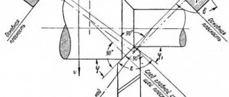
- Machining planes
- Types of turning cutters and their purpose
- Main rules for choosing a tool
- When sharpening is required
- How to attach a cutter to a machine
One of the main parts of the machine deserves detailed consideration. Therefore, the focus is on the geometry of the turning tool: the main elements and angles, surfaces and other characteristics. You will also learn how its different types differ from each other, for example, what is the difference between threading and boring, and you will be able to choose one or more of them, depending on your production or domestic needs.
Let us immediately note the importance of the role of those indicators discussed below. They, in fact, determine not only the functional purpose, but also the reliability of the edges, and therefore the duration of operation of the device. They also determine the productivity and accuracy of technological operations, and, finally, orientation in space when solving a problem.
Tool Options
Any of them consists of two structural elements. This is a holder responsible for high-quality fixation in the machine, and a working head that directly removes excess layers of material.
And each of them has three turning tool surfaces:
- the front one is responsible for chip collection;
- main (primary) and auxiliary (secondary) rear ones, facing the workpiece.
- The intersections form the edge and form the apex, that is, the sharpest point experiencing maximum loads. To prevent it from chipping, it is slightly rounded to improve durability (introducing the concept of radius into the technical documentation) or, alternatively, a straight transition is made.
But there are also parameters whose role is even more important, because they determine the relative position of all three planes. These are angles, the calculated values of which depend on a number of factors, and in the list of key ones:
- operating conditions and intensity;
- instrument material;
- hardness, viscosity and other quality characteristics of the workpiece.
They need detailed consideration.
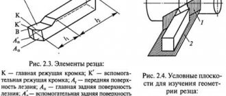
Structural elements of the cutter
| Rice. 1. Structural elements of the cutter Rice. 2. Top of the cutter | The cutter consists of: Heads – working part of the cutter. Holders - mounting part of the cutter. It is the body of the cutter and serves to secure the cutter to the machine. The cutter head contains:
During the cutting process it comes into contact with the cut layer and chips.
Contacts the cutting surface.
Facing the treated surface.
Formed by the intersection of the front surfaces 1 and the auxiliary rear 3.
Formed by the intersection of the cutting edges of the main 4 and auxiliary 5. |
| The top of the cutter is made: - either along the radius They improve the roughness of the machined surface and increase the durability of the cutter. | |
Basic angles of metal turning tools and their purpose
Their accuracy must be ensured down to one or two degrees. To do this, you need to clearly monitor the relationships between the mutual inclinations of the three surfaces already considered.
Main rear
It is marked (α), its role is to reduce friction in the zone of mechanical interaction, and should not be “floating”. You need to understand that its expansion entails a serious reduction in the strength of the tool - at some point, with excessive force, it may simply break - and even worsens the fixation of the shank in the holder, which reduces overall labor safety; in addition, it provokes the appearance of beating and increases the frequency of vibrations, increasing their amplitude, and therefore accelerates wear. And vice versa, its narrowing increases the contact area, as a result of which the accuracy of the technological operation decreases.
Main front
It is written down on the drawings (γ), and it determines both the geometric parameters of the turning cutter and the final dimensions of the part, since it is responsible for reducing the deformation of the layers being removed. If it is narrow, the material is removed quickly, but in a targeted manner. Accordingly, as it expands, the captured space becomes larger, but the force of impact is weakened, which negatively affects overall performance. Also, the thickness of the blade decreases, which is fraught with deterioration in strength and heat dissipation, and more frequent chipping.
It may even be negative - for tools used for stripping under shock load; they are in demand because they absorb pressure with their entire front part, and not just the edge.
cutting
It is designated (δ) and determines the ease and depth of penetration of the device into the thickness of the workpiece material.
Equal to the sum of α and β (which is next in line). In the vast majority of cases, it is performed within 60-100 degrees.
Points
It's labeled on the drawings (β), and it talks about the shape of the top. The duller (wider), the stronger the blade is under conditions of intensive use.
Basic angle of turning tool
It is written as (φ), and it determines both the speed of the technological operation and the physical strength of the tool, which are higher the narrower it is. But it should not be too small, as this is fraught with the occurrence of vibrations due to excess radial forces.
Located between the edge projection and the workpiece feed vector.
Secondary in plan
It is designated (φ1) and has a significant influence on the cleanliness of the part: the wider it is, the more roughness the workpiece has; but remember that as its value decreases, heating increases.
Rear auxiliary
It is marked (α1) and it helps eliminate friction at the point of contact of the blade with the part, preventing an increase in temperature in this area, and therefore protecting against premature wear. As it increases, the strength of the device decreases, and if it goes beyond the recommended limits, this provokes a breakdown.
Apex between cutter edge and flank auxiliary surface
Already from the subtitle it is clear at what intersection point it is measured. And the sharper it is, the better the material is removed, but the faster the contact zone heats up, and the worse the resistance to mechanical damage, and therefore the lower the service life.
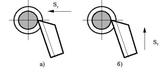
Tilt
Denoted by (λ), can be positive, zero or negative. Its indicator determines in which direction the metal (wood, plastic) shavings will flow when performing a technological operation.
For example, if λ < 0, that is, negative, the waste falls in the same direction in which the movement occurs.
Selecting the angle of inclination of the main cutting edge
The angle of inclination of the main cutting edge ( ) affects the roughness of the machined surface, because determines the direction of chip flow and the strength of the cutting wedge of the tool.
Angle l can be positive, negative, equal to zero (Fig. 1.5). The angle λ is negative when the tip of the cutter is the highest point of the cutting edge, positive - the lowest point.
If the angle l = 0, the chips will move towards the cutting surface.
If the angle l is positive, the chips will all the more move towards the machined surface; this direction of chip flow will worsen the roughness of the machined surface.
In the case of a negative angle l, the chips will flow in the direction of the machined surface. Therefore, during finishing, l must be negative, and during roughing, positive or equal to zero.
From the point of view of the strength of the cutting wedge of the tool, it is necessary to choose angles l that are positive or equal to zero. This is due to the fact that at a negative angle l the greatest load falls on the tip of the cutter, which is the least strong place of the cutting part. When the angle l is positive or equal to zero, the load does not fall on the tip of the cutter, but on the part of the cutting edge remote from it, which is stronger than the tip.
1.3.4 Selecting the main and auxiliary angles in plan
These angles influence the roughness of the machined surface and tool wear.
Reducing the angles j and j1 leads to a decrease in the roughness of the machined surface and an increase in the tool life period, but at the same time, to an increase in the force pushing the cutter away from the workpiece (Pu force), which can lead to vibration. Therefore, the main angle in the plan should be selected based on the rigidity of the workpiece.
When finishing rigid workpieces, the angle φ must be taken smaller in order to ensure higher tool performance and a lower height of micro-irregularities of the machined surface; when processing non-rigid workpieces, the likelihood of vibrations must be taken into account (to reduce the cutting force component Ru, the main angle in the plan should be increased).
The auxiliary plan angle for cutters is usually taken in the range of 10...30o.
Measuring the sharpening angles of a turning tool
For maximum accuracy of the result, it must be performed only with specialized manual equipment. It consists of the following parts:
- base - all other elements are attached to it;
- movable template for the stand, adjustable to a convenient position;
- graduated scale making it possible to read readings;
- a locking screw that allows you to mark and store the direction of value changes.
The algorithm for recording the results is as follows:
- place the tool;
- apply its edge;
- look how much it shows - the found figure will be the actual degree.
The method is easy to implement and quite accurate. By the way, taking into account possible differences in the geometry of turning tools, it is recommended to determine the entering angles using equipment equipped with a vernier.
Machining planes
The following types are distinguished:
- the main one – goes parallel to the feed vector, be it longitudinal or transverse;
- cutting - it is formed by the blade (directly) and the area on which it acts (tangentially).
Plus, there are a couple of secants - the main one and the additional one. The direction of the first is through the free point of the tip perpendicular to the projection, the second is created in a similar way and also at a right angle, only through the auxiliary edge.
All obtained values should be recorded, thus maintaining technical documentation, which, if necessary, will help calculate the accuracy, speed, quality of material removal and the approximate service life of the tool, taking into account the intensity of its use.
Types of turning cutters and their purpose
The entire set of devices existing today can be conditionally classified according to a number of characteristics:
- nature of execution - prefabricated (from soldered carbide plates) or solid (made from a monolithic bar);
- technological role – general (for standard operations) and special (for complex profiles);
- blade configuration - straight or curved (for parts with hard-to-reach places), the latter - with a wide variety of curvature shapes;
- processing class – rough (rough, for peeling) and finishing (fine, for finishing);
- feeding feature - to a stationary workpiece (planing) or to a rotating one.
To facilitate classification, the design of a turning tool or its key differences is often reflected in its name. For example, it is immediately clear from a diamond that it is intended for removing layers of superhard materials. The main part of the spring resembles a spiral and slightly cushions under load. We think it’s clear what shape the blade is, what the nature of the impact of the slotting machine seems to be clear without further ado.
Now let’s take a closer look at those popular groups of tools that are used regularly today.
Passing
The most common and more than in demand for external processing of cylindrical parts. Divided into three categories:
- straight - their blade runs strictly parallel to the axis of rotation of the machine equipment;
- bent - their edge is located with a deviation to the left or right (relative to the holder), which makes it possible to significantly facilitate the longitudinal feed;
- persistent - already with two bends, as a result of which the head of the device acquires a ϟ-shaped shape that supports the part and prevents it from bending; This makes them suitable for removing material from non-rigid or long objects.
The differences between the elements and angles of a turning cutter are clearly visible in the diagram below. We will add that all 3 varieties are produced and used on a truly massive scale. Therefore, in order to make reasonable savings without compromising quality, they are most often made non-separable and made from tool grades of steel.
Scoring
Needed to create ledges and trim rotating objects. They are good for their ability to support each of the feeding directions - this allows you to easily form any ledges you want. They are usually prefabricated, since they are not subject to strict reliability requirements.
Cut-off
They belong to the group of groove blades and are distinguished by a specific blade configuration: the main edge of any of them is supplemented by a pair of auxiliary ones (one on each side), which also affect the side planes at the point of contact. It is also made trapezoidal, tapering towards the holder, in order to reduce friction. But the head is strengthened and, if bent upward, is called a cockerel head.
It is important to position such a tool directly opposite the axis of rotation and as close to the chuck as possible, placing the body perpendicular to the part, if necessary, using fluid for lubrication and cooling.
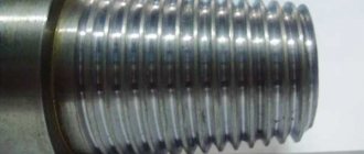
Threading
Maintain high accuracy of alignment of the machine shaft with the workpiece area. Due to the maximum matching of profiles, the reliability of the final result is ensured. Depending on the surface being processed, they are divided into 2 types:
- internal ones are bent, they need to be inserted into a hollow workpiece;
- external ones are straight, with the most convenient access.
In each case, it is important to synchronize the feed with the spindle speed.
Boring
Needed to ensure alignment: such a device is inserted into a cylindrical part and removes excess material until it fits perfectly onto the shaft.
It is worth considering that the operation is performed under conditions of high heat and difficult removal of chips and the use of coolant, so it must be performed at low speeds and without going too deep.
Divided into 2 types:
- persistent - for dead-end holes;
- pass-through - for through.
Their holders can also be of different sizes.
Prefabricated
Here, the structure of a turning cutter consists of an all-metal profile and a removable plate, either soldered (welded) or mechanically attached. In the second case, fixation is carried out using clamps, a threaded connection or eccentrics - the main thing is that it is sufficiently reliable.
To create a durable blade, it is also important to choose the right material. This can be either “classic” tool steel or even harder alloys or, alternatively, powder composites.
Turning cutters. Basics of the metal cutting process
Conditions for high productivity of mechanical cutting tools
The action of cutting tools used on metal machines, in particular turning tools, depends on three main conditions: 1) on the stability of the workpiece, i.e. on the strength of its material and the method of fixing it on the machine; 2) on the strength of the tool, in other words, on its size and method of fastening; 3) on the shape of the cutting part of the tool.
Proper stability and strength of the machine is also, of course, necessary.
The person working on the machine usually has to sharpen and install the cutters required for the job himself, and therefore he must be well acquainted with the requirements for them.
Turning cutters
Forged turning tools
- The scoring cutter (on the right in the figure) is used for end (frontal) turning. Has side and front clearance. The cutting edge is sharpened at such an angle that the cutter does not touch the rear center of the machine when approaching the center of the surface being ground. The cutter has only a transverse slope. There is no longitudinal slope.
- The sharp-nosed incisor (right in the figure) is now rarely used, as it has been replaced by “normal” Taylor incisors.
- Curved, sharp-nosed incisor (left in the picture). The ends of most types of incisors often bend to the right or left. For some jobs, eg when processing shoulders, this is convenient.
- Normal through cutter. This type of cutter was developed by Taylor as a result of many years of experience, which showed that this form of cutter is the most advantageous for turning. The average longitudinal slope is 8°, the average transverse slope is 14°. In what follows, for brevity, this incisor is called “normal.”
- Cut-off cutter. Discussed in detail in §§ 147 and 148.
- Round-nosed incisor. The cutting edge is rounded to an arbitrary radius, which distinguishes it from a normal cutter. Used for cutting semicircular grooves, fillets (fillets), shoulders, etc.
- Brass cutter. It is sharpened like a type 6 cutter, the tip of which is rounded to a small radius. It has neither longitudinal nor transverse slope, in order to avoid cutting the cutter into soft brass.
- Wide finishing cutter. Very useful for aligning front centers and turning short tapers. It is often used with large feeds to remove the finest finishing chips from cast iron. It has no longitudinal slope.
- Spring cutter. For turning wide shoulders and other shaped work where it is necessary to remove wide chips, as well as for finishing cast iron and steel (with water). When this cutter springs, its cutting edge moves away from the surface being processed.
- Flat (blunt-nosed) incisor. Very convenient for frontal turning of large diameter ends when a lot of metal needs to be removed. Feed from the circumference to the center. It is also used for finishing steel, with large feeds and small depths of cut (“thin chips”). For the cleanest finish, cool with water and soda. It has only a longitudinal slope, no transverse one. Lateral clearance - on both sides, therefore, can work as a right-handed or left-handed cutter.
- Centering cutter (cutter-drill). It is sharpened at an angle of 120°—corresponding to the angle of the tip of the twist drill. Works similar to the perk. The gap of both cutting ribs is directed in opposite directions. Used to mark the center of holes to be drilled with a twist drill.
- Cutter for cutting screw threads. Its toe is sharpened exactly according to the thread profile. For details, see chap. 16,
- Boring cutter. See § 162.
A lathe is used for a wide variety of work - turning, threading, boring holes, etc., and each operation requires specially shaped cutters. In fig. 62 shows various types of forged turning tools. However, recently they are gradually being replaced by more economical cutters of small sizes, inserted into special holders (see Fig. 66).
The basic principles underlying the choice of cutter sharpening angles, clearance angles, etc., set out in further paragraphs, are common to all metal cutting tools. Anyone who knows why a turning cutter is sharpened this way and not another, knows why certain bevel angles are chosen, etc., and knows how to hold the cutter on a grinding wheel while sharpening, will quickly learn how to properly sharpen other tools and understand which they must have a form.
The material from which the cutters are made must be sufficiently hard and tough to withstand the forces exerted on the cutter during cutting. Therefore, metal cutting tools are made of steel, hardened and then tempered.
Cutter point angle
The action of each cutting tool is similar to the action of a wedge, which pushes the particles of material apart. In relation to the cutters, the angle of the wedge formed by its edges is called the point angle of the cutter or, in short, the angle of the cutter (see Fig. 63).
The harder the material being processed, the stronger the cutter blade should be, i.e. the greater the angle of its sharpening should be. The angle of the cutter, suitable for wood, is not suitable for processing iron or steel, since its value will soon change due to the fact that the cutting edge will round off (“give in”) under the influence of the high cutting resistance of the metal. For metal cutters, the sharpening angle is made from 60° to 80°, depending on the hardness of the metal being processed.
Clearance angles
The action of a cutter removing shavings from metal is similar to the action of a knife used to peel an apple. The chips being removed rub against one of the faces forming the wedge, while the other face should not touch the product and therefore makes a certain small angle with it, the so-called. side clearance angle (Fig. 63). This angle should not, generally speaking, be more than 6°, since as it increases, the angle of the cutter decreases, therefore, the cutter will have to be sharpened more often.
The action of the cutting resistance force on the turning cutter is directed tangentially to the circumference of the workpiece being turned at the point of contact of the cutter with the workpiece (see Fig. 64). Since the top is the so-called. the toe of the cutter is usually installed at the height of the center line or slightly above it, then in order to avoid friction between the product and the front edge of the cutter, this face is given some slope. The angle between the rake face and the cutting direction is called the rake clearance angle or, in short, the clearance angle. Its usual value is about 10°. However, it depends on the height of the cutter in the support.
Cutting edge slope angles
In order to obtain the required sharpening angle, it is necessary to grind off the upper (cutting) edge of the cutter so that it has both a longitudinal slope - from the cutting edge back - and a lateral slope - from the cutting edge in the direction opposite to the feed. Otherwise, the sharpening angle of the cutter will not be sharp enough. The slope from the toe of the cutter back is called the longitudinal slope angle of the cutting edge, and the lateral slope is called its transverse slope angle (Fig. 65). The magnitude of these angles depends, naturally, on what sharpening angle is required, since the greater the slope, the smaller the angle of the cutter, i.e. the sharper the cutting wedge formed by its edges. For turning cast iron and tool carbon steel, the cutter angle should average about 70°, for mild semi-finished steel - 60°. When sharpening a cutter, first remove the clearance angle, then the slope angles, in such a way as to obtain the sharpening angle required for processing the material.
Compared to steel, brass is a soft metal and therefore, to process it, it would not be necessary to give the cutter the same large sharpening angle as a cutter for steel. However, in reality, bevel angles are usually not sharpened on brass cutters, since sharp cutters tend to “eat in”, i.e. delve into soft material.
Tool holders
High speed steel cutters are approximately twice as productive as carbon tool steel cutters. Therefore, recently turning cutters, as well as other cutting tools for metal processing, have been made mainly from high-speed steel. Since it is much more expensive than carbon steel, various holders have become widespread, in which a small piece of high-speed steel, sharpened accordingly, is securely fixed. This results in savings not only on the cost of steel, but also on the costs of forging cutters.
In fig. Figure 66 shows several common types of tool holders. In fig. 67 are shown on the right - inserted turning cutters (plates) made of high-speed steel, sharpened for various jobs, on the left - the operation of these cutters mounted in holders.
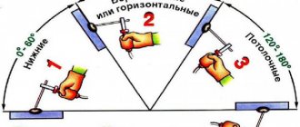
Sharpening cutters
A properly sharpened cutter, when used under normal conditions, remains sharp for quite a long time. As soon as it shows signs of dullness, it is necessary to immediately resharpen it, otherwise not only the cutter will suffer, but also the product being processed by it. A dull cutter does not so much cut metal as tear out particles of it, so the surface being processed cannot be smooth. One of the main factors in the productive operation of the machine is a sharply sharpened cutter.
It must be remembered that improper sharpening of cutters places a heavy burden on the cost of products simply by the cost of excessively worn material of cutters and grinding wheels. Where should the cutter be sharpened - from above, from the front, from the side, or from all sides a little? It is impossible to give definite rules in this regard, and when sharpening a cutter you should proceed from the work for which it is intended. The method of sharpening largely depends on how long the cutter should work without regrinding and how long it should last in total.
When sharpening a carbon steel cutter, you should not press it too hard against the grinding wheel, otherwise the cutting edge will heat up (usually it turns blue) and release, i.e. its hardening will be lost. It is preferable to use a wet sharpener. High-speed steel cutters do not lose their hardening so easily, but sometimes, if there is not enough water, cracks appear on their surface. Therefore, firstly, you should not spare water, and secondly, you should not press too hard on the cutter while sharpening.
Do not keep the cutter in one place, move it so that it is pressed against different places on the cylindrical surface of the circle. In this case, the cutter must be gradually rotated, as shown in Fig. 68, i.e., so that it takes sequential positions a, b, c.
Small cutters should not be sharpened in holders, because, firstly, it is inconvenient, and secondly, the end of the holder can be ground down at the same time. In fig. 69 shows how to hold such cutters while sharpening.
It is recommended for a beginner to practice first on small pieces of simple ornamental steel of a suitable shape and only then proceed to sharpening high-speed steel insert cutters. At first, obtaining the correct clearance angle on such a cutter by sharpening presents some difficulties, since for work the cutter is inserted into the holder at a known angle. Therefore, at first, while there is no skill, it is best to use a template. In cases where it is necessary to obtain a relief angle of 10°, it is convenient to use a template for turning centers (see Fig. 85), the angle of which is 60°, since in most holders the cutter is fixed so that its upper edge is 20° with the horizontal (Fig. 70). If the cutter angle is other than 60°, it is not difficult to cut a corresponding template from a piece of sheet metal.
What not to do when sharpening a cutter
- Don't sharpen the cutter at random; be aware of where and how much metal needs to be removed.
- Hold the cutter firmly and confidently.
- Do not press the cutter to the circle with your left hand; hold it properly, that's the easiest thing.
- Don't skimp on water.
- Do not keep the cutter in one place on the grinding wheel all the time, otherwise you will cut a groove on it.
- If possible, do not use a circle that has lost its correct cylindrical shape or whose surface is heavily chipped.
- Do not sharpen a cutter on the end surface of a circle unless necessary: when you need to sharpen on the end, its surface will no longer be flat, but scratched by you or someone else.
- Do not rest the insert cutters on the tool rest: hold them in your left hand and rest your hand on the tool rest.
- Do not move the tool rest further than 1.5-2 mm from the grinding wheel.
- Do not round the tip of a thread cutter or turn a round nose cutter into a thread cutter: this is a waste of material and time.
Main rules for choosing a tool
- Decide in advance why it is needed and in what modes you plan to use it.
- Consider the production purpose - the capabilities of something that is great for one-time or rare use in a garage or personal workshop are unlikely to be enough for industry, with its mass production.
- Focus not on the price (too low a cost should even scare you away), but on durability, which you can see in the table of turning tools.
- Pay attention to whether the blade can be edited - if it lasts comparatively longer, but cannot be re-sharpened and must be replaced after the first dullness, you will end up spending more.
When sharpening is required
There are two cases in which it is necessary:
- the edge has worn out and lost its useful qualities;
- a new tool is released.
In both cases, it must be carried out, otherwise you simply will not be able to process the part with the required accuracy and ensure the required surface quality. Plus, during the process, the workpiece will probably additionally suffer from beating and vibration.
So be sure to do it when it is required, that is, regularly and in a timely manner; Thus, you will provide the blade with the necessary sharpness and reliability, which will have a positive impact on the overall level of safety of technological operations on the machine.
Rules for sharpening
- use only a suitable abrasive wheel;
- work with gloves and a mask (goggles), do not forget about protection;
- clean all the main parts and elements of the turning cutter from dust and dirt and fix it in the tool rest, adjusting the position;
- first of all, remove the rear corners and only after measuring and checking them, proceed to the front ones;
- do not neglect fine-tuning - it is needed in every area where even the smallest irregularities are observed.
Tools used
The base in this case is a pair of grinding wheels: one is made of green silicon carbide, the other is made of electrocorundum. The first is suitable for materials with a high degree of hardness, the second for softer tool steels.
You will also need a grinding machine for finishing operations. Since the latter are considered thin, the equipment must operate at low speeds with the lowest possible level of runout. A diamond or CBN surface is suitable as an abrasive.
How to attach a cutter to a machine
It is installed on the caliper carriage (moving element) and fixed with a holder, which can be either single- or multi-position. Attention, its position must be adjusted with maximum accuracy: it must be placed parallel and perpendicular at the same time. The edge is strictly opposite the shaft axis, take time to adjust the height. Steel plates will help with centering.
Also, gaps or backlash should not be allowed, which can lead to the tool becoming loose (over time and under loads), and therefore to a decrease in the accuracy of machining parts. Therefore, the fasteners must be rigid.
We explained in detail what parts a turning cutter consists of, what angles it has and why they are needed. Now you probably understand how important it is to maintain its profile geometry in the recommended condition and, if necessary, you can sharpen it. Well, you will always find a machine for this in the Izhevsk catalog - contact us and buy high-quality equipment.
Types of cutters
Types of turning tools
According to technological purpose, turning tools are divided into:
- Cut-off. Not a single part can be manufactured without them. This group can be used not only for its intended purpose - processing the end elements of the part and cutting off the finished piece from the piece from which it was made. Most often you can find cutting cutters of classical shape on sale. Each turner uses the most convenient cutting tools on his own lathe using overlay plates.
- The pass-through is used for processing rotating cylindrical workpieces. Tool sharpening angles may vary depending on the lathe's convenience when processing the part.
- The scoring machine is used in processing the end parts of the workpiece and creating ledges on the outside of the manufactured part. When trimming the ends, it is more convenient to move the scoring cutter from the center towards the outer part of the workpiece. With this feeding method, the scoring tool is positioned towards the surface to be processed so that cutting is ensured by long-edged plates. When the scoring tool is fed from the outer part to the axis of rotation of the part, the short-edge cutting inserts work. The processing result is less accurate and clean. The scoring tool, when used to trim the ends of a part secured at centers, is used only if the rear center is to be replaced by a half-center. This is necessary to preserve the plates. Otherwise, it will not be possible to avoid their damage due to contact with the full rear center.
- A groove cutter has a thinner cutting edge than a parting cutter. When turning a wide but shallow groove, a groove cutter can replace cut-off cutters. Grooving tools are made in two types - straight and bent. Their cutting edge is selected in accordance with the required width of the groove. The peculiarity of the groove type is that the height of the head significantly exceeds the height of the cutting edge. This design feature increases strength, making the thin-edge groove turning tool able to withstand heavy loads.
- Boring tools are used for making blind and through holes without the use of drilling equipment. Holes made using cutters have greater accuracy. Various types are used to make closed and through holes.
- Threaded. To cut threads on the internal and external surfaces of a part, tools are used that differ in width and type of working head. To work on a lathe, it is not always enough to use classically shaped cutters and install the part correctly. The types of threads made on turning equipment have different angles, which means a wide range of inserts that are sharpened at different angles. Types of internal and external threads are produced using different technologies. To make the work less labor-intensive, it is better to use the right tool for a specific operation. It is more convenient to cut if the angles of the cutting edge and the required thread angle coincide. To do this, you need to sharpen the cutting blades yourself. The sharpening angles of most cutters correspond to 60⁰. If necessary, you can change the angles of the head, if it is not classified as non-sharpenable, on a sharpening machine.
Principles of turning