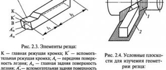
Cutter elements
Cutting planeCutter angles
Cutting planes
To determine the cutter angles, the initial planes are established: the main plane and the cutting plane (Fig. 1.6).
Cutting plane - a plane tangent to the cutting surface and passing through the cutting edge.
The main plane is a plane parallel to the directions of longitudinal and transverse feed. For turning and planing cutters of a prismatic rectangular shape, the supporting surface of the cutter can be taken as this plane. For slotting cutters, the main plane is perpendicular to the supporting surface.
Let's consider the parts and angles of the cutter in accordance with GOST 6897 and 6898.
Figure 1.6 - Surfaces and initial planes of the cutter during turning, planing and chiselling
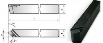
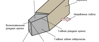
Figure 1.7 - Elements of the cutter. Figure 1.8 - Height and length of the cutter head
Cutter elements
The cutter (Fig. 1. 7) consists of a head , i.e. the working part of the cutter, and a body, or rod, which serves to secure the cutter in the support or holder.
The height of the cutter head (Fig. 1.8) is the distance between the tip of the cutter and the supporting surface, measured perpendicular to this surface. The height of the head is designated by the letter h and is measured in millimeters. The height of the cutter head can have a negative value.
The length of the cutter head (see Fig. 1.8) is the greatest distance from the tip of the cutter to the exit line of the sharpening surface, measured parallel to the longitudinal edges of the cutter body. The length of the holo is designated by the letter l and measured in millimeters. There are front and rear surfaces, cutting edges and the tip of the cutter (see Fig. 1.7).
The rake surface is the surface of the cutter along which the chips flow. Back surfaces are the surfaces of the cutter facing the workpiece.
Cutting edge - an edge formed by the intersection of the front and rear surfaces. There is a main cutting edge, which performs the main cutting work, and an auxiliary cutting edge. Cutters can have one (for example, pass-through) or two (for example, cutting; auxiliary cutting edges).
The flank surface adjacent to the main cutting edge is called the main flank surface.
The tip of the cutter is the place where the main cutting edge meets the auxiliary ones. The apex of the cutter can be sharp or rounded in plan.
Types of incisors
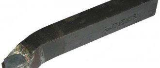
Incisors can be right or left .
Right incisors (Fig. 1.9, b) are incisors in which, when the palm of the right hand is placed on top of them so that the fingers are directed towards the top, the main cutting edge will be located towards the thumb. On a lathe, these cutters work when feeding from right to left, that is, towards the headstock of the machine.
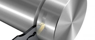
Left incisors (Fig. 1.9, a) are incisors in which, with the indicated method of applying the left hand, the main cutting edge will be located towards the thumb. The cutter head can have different shapes and different locations relative to the cutter shaft (Fig. 1.10).
Figure 1.10 — Shapes of cutters
Figure 1.9 - Cutters. a - right, b - left
Figure 1.11 — Cutter angles in a static state
Straight incisors are those incisors whose axis (axis of symmetry) is straight in plan and side view.
Bent incisors are those incisors whose axis is straight in lateral view and curved in plan view.
Curved incisors are those incisors whose axis is straight in plan view and curved in lateral view.
Incisors with a retracted head are those incisors whose heads are narrower (thinner) than the body. The head can be located relative to the axis of the cutter body either symmetrically, or on one side, and the head can be straight, bent to the side or curved.
pulled to the right (or left) are those in which, with the previously indicated method of applying the palm of the right (or, respectively, left) hand, the head is shifted towards the thumb.
Let us consider the angles of the cutter as a geometric body at rest (static state). Below we consider the angles of a straight cutter, the axis of which is set perpendicular to the direction of the longitudinal feed, and the apex is located along the line of centers (Fig. 1. 11). There are main angles , auxiliary angles and plan angles .
Cutter angles
The main angles of the cutter are measured in the main cutting plane perpendicular to the projection of the main cutting edge onto the main plane. These include the following angles.
The main clearance angle α is the angle between the marks of the main clearance surface of the cutter and the cutting plane.
The sharpening angle β is the angle between the marks of the front and main back surfaces of the cutter.
Rake angle γ is the angle between the trace of a plane perpendicular to the cutting plane passing through the main cutting edge and the trace of the rake surface of the cutter.
Cutting angle δ is the angle between the rake surface mark and the cutting plane. Usually δ = α + β = 90° - γ (1.5)
Auxiliary cutter angles α1, φ1, β1 are measured in the auxiliary cutting plane (see Fig. 1.11) and are determined by analogy with the main cutter angles.
Plane angles are measured in the main plane.
The main angle φ is the angle between the projection of the main cutting edge onto the main plane and the feed direction.
Auxiliary angle φ1 is the angle between the projection of the auxiliary cutting edge onto the main plane and the direction of feed.
Plane apex angle ε
- the angle between the projections of the cutting edges onto the main plane.
From Fig. 1.11 it is clear that ε
+ φ + φ1 = 180°. (1.6)
The inclination angle of the main cutting edge λ is the angle between the cutting edge and a straight line drawn through the tip of the cutter parallel to the main plane. This angle is measured in a plane passing through the main cutting edge perpendicular to the main plane.
Similar materials
Holders and their sizes
We have looked at what types of cutters there are for a lathe, now let’s return to the part with which they are fixed in the equipment. During the review process, we have already repeatedly mentioned the most popular dimensions, now let's list them in full - from smallest to largest. For clarity and ease of perception - in the form of the following table:
| section | size, mm | |||||||||
| square | 4 x 4 | 6 x 6 | 8 x 8 | 10 x 10 | 12 x 12 | 16 x 16 | 20 x 20 | 25 x 25 | 32 x 32 | 40 x 40 |
| rectangle | 16 x 10 | 20 x 12 | 25 x 16 | 25 x 20 | 50 x 52 | 40 x 32 | 50 x 32 | 50 x 40 | 63 x 50 | — |
It is also necessary to take into account the variety of lengths needed in specific cases, for example, for boring holes. This parameter usually varies from 150 to 300 mm. We have tried to cover in as much detail as possible the issues of the variety of metal turning tools, markings and purposes of their various options, so that you understand which one to choose for the required technological operation. Well, you can find equipment that is compatible with most of these tools at the Izhevsk plant.
Principal angles
One received the name - the main front angle. The second one is called the main rear one.
Each influences the processing result:
- The first directly determines the quality of the surface being removed (the resulting chips). If it increases, increased deformation occurs in the upper layer. A low value allows the tool to remove excess metal much easier. Does not cause increased compression of this layer. Significantly facilitates the process of removing and draining excess metal.
- An increase in the numerical value of the second weakens the reliability of fastening the tool to the tool holder. Promotes an increase in the frequency and amplitude of vibrations. Changing the characteristics increases the wear rate of the cutter. Decreasing the value increases the contact area of the cutting edge with the machined surface. This leads to an increase in the temperature of the cutter.
Angle of inclination of the cutting edge of the cutter
Classification of turning tools
There are several features according to which the existing models are divided into groups. We invite you to take a closer look at exactly what features.
By manufacturing method:
- Monolithic (solid) - the head with the holder are made inextricably, from the same workpiece, from steel (usually alloyed).
- Prefabricated - a carbide plate is applied to their working part by soldering.
- Removable (adjustable) - similar to the previous ones, with the only difference that the reinforcement element is usually made of cermet and secured with bolts (screws, clamps), which means it can be dismantled and replaced.
In the direction of travel:
- right - in practice they are used much more often; to check, place the appropriate hand on the surface - the cutting edge of the tool should be located on the side where the thumb is looking at the part;
- left - used less often; if we compare them with their more popular counterparts, they are served in the opposite direction, which means that their blade, if you bring your palm up, will be on the other side.
Now let's return to the issue of dimensions and see, taking into account the specific features, what kind of cutters there are for a lathe in terms of their geometry.
According to the shape of the holder:
- square - sizes from 4 by 4 to 40 by 40 mm;
- rectangular - with an aspect ratio from 16 by 10 to 63 by 50 mm.
We discussed the structure of the head above, and we remind you that according to this parameter, instruments can be straight, curved, bent or drawn. There is another important point - the function that they will perform.
By type of destination:
- cutting - for molding blanks with straight edges (corners);
- pass-through – for ends, chamfering, external surfaces;
- groove - to create grooves of the required depth;
- boring – for processing holes, through and/or blind type;
- threaded – for making screw connections.
By the nature of the work performed:
- peeling (roughing) - layers of material are removed quickly, but without much care;
- semi- and finishing – for more thorough and accurate technological operations;
- thin – for quickly solving especially critical and even precision tasks.
By installation method:
If we consider how the type of turning cutters and their purpose depend on the characteristics of fixing the workpiece being processed, the classification will be carried out according to the location option:
Radial - that is, at an angle of 90 degrees to the axis of the part; This is a classic option for most industrial enterprises, where it is important that the mounting and geometric positions of the tool are unified. Tangential - the edge is at an indirect angle; This type of installation is used relatively less frequently because fixation is more difficult, but it is relevant for non-standard cases that require maximum precision.
According to the material of the cutting part:
- Carbon metals with a hardening hardness of 60-64 or based on chrome-silicon, chrome-tungsten; are used relatively rarely, as they quickly overheat even at 240 or 300 degrees, and therefore already show poor results.
- Steel hardened to 62-65, categories R9K5F2, R9, R12; They are often used because they cannot be wiped and even at high rotation speeds they are able to retain their properties and withstand temperatures up to 650 0C.
- Metal ceramics - alloys based on tungsten-cobalt (VK8, VK6 - for cast iron) or titanium-tungsten-cobalt (T15K6 is especially popular); do not deform even at 900 degrees Celsius.
The markings deserve special attention: the designations of metal turning tools consist of 9 or 10 characters. Each number (or letter) regulates:
- 1st – installation option;
- 2nd – plate shape;
- 3rd – type of tool;
- 4th – back angle value;
- 5th – direction of movement;
- 6th – holder height;
- 7th – tail width;
- 8th – total length;
- 9th – edge size;
- 10th - is added optionally when necessary, and determines the key (for a given case) accuracy parameters.
Now, in order not to complicate the review, it’s time to move on to the most detailed consideration of the most frequently used options - so that you have a complete understanding of how, when and what they are used for.
Types of turning cutters and their purpose
The entire set of devices existing today can be conditionally classified according to a number of characteristics:
- nature of execution - prefabricated (from soldered carbide plates) or solid (made from a monolithic bar);
- technological role – general (for standard operations) and special (for complex profiles);
- blade configuration - straight or curved (for parts with hard-to-reach places), the latter - with a wide variety of curvature shapes;
- processing class – rough (rough, for peeling) and finishing (fine, for finishing);
- feeding feature - to a stationary workpiece (planing) or to a rotating one.
To facilitate classification, the design of a turning tool or its key differences is often reflected in its name. For example, it is immediately clear from a diamond that it is intended for removing layers of superhard materials. The main part of the spring resembles a spiral and slightly cushions under load. We think it’s clear what shape the blade is, what the nature of the impact of the slotting machine seems to be clear without further ado.
Now let’s take a closer look at those popular groups of tools that are used regularly today.
Passing
The most common and more than in demand for external processing of cylindrical parts. Divided into three categories:
- straight - their blade runs strictly parallel to the axis of rotation of the machine equipment;
- bent - their edge is located with a deviation to the left or right (relative to the holder), which makes it possible to significantly facilitate the longitudinal feed;
- persistent - already with two bends, as a result of which the head of the device acquires a ϟ-shaped shape that supports the part and prevents it from bending; This makes them suitable for removing material from non-rigid or long objects.
The differences between the elements and angles of a turning cutter are clearly visible in the diagram below. We will add that all 3 varieties are produced and used on a truly massive scale. Therefore, in order to make reasonable savings without compromising quality, they are most often made non-separable and made from tool grades of steel.
Scoring
Needed to create ledges and trim rotating objects. They are good for their ability to support each of the feeding directions - this allows you to easily form any ledges you want. They are usually prefabricated, since they are not subject to strict reliability requirements.
Cut-off
They belong to the group of groove blades and are distinguished by a specific blade configuration: the main edge of any of them is supplemented by a pair of auxiliary ones (one on each side), which also affect the side planes at the point of contact. It is also made trapezoidal, tapering towards the holder, in order to reduce friction. But the head is strengthened and, if bent upward, is called a cockerel head.
It is important to position such a tool directly opposite the axis of rotation and as close to the chuck as possible, placing the body perpendicular to the part, if necessary, using fluid for lubrication and cooling
Threading
Maintain high accuracy of alignment of the machine shaft with the workpiece area. Due to the maximum matching of profiles, the reliability of the final result is ensured. Depending on the surface being processed, they are divided into 2 types:
- internal ones are bent, they need to be inserted into a hollow workpiece;
- external ones are straight, with the most convenient access.
In each case, it is important to synchronize the feed with the spindle speed
Boring
Needed to ensure alignment: such a device is inserted into a cylindrical part and removes excess material until it fits perfectly onto the shaft.
It is worth considering that the operation is performed under conditions of high heat and difficult removal of chips and the use of coolant, so it must be performed at low speeds and without going too deep.
Divided into 2 types:
- persistent - for dead-end holes;
- pass-through - for through.
Their holders can also be of different sizes.
Prefabricated
Here, the structure of a turning cutter consists of an all-metal profile and a removable plate, either soldered (welded) or mechanically attached. In the second case, fixation is carried out using clamps, a threaded connection or eccentrics - the main thing is that it is sufficiently reliable.
To create a durable blade, it is also important to choose the right material. This can be either “classic” tool steel or even harder alloys or, alternatively, powder composites
Classification
According to the design and principle of operation, this tool is differentiated into the following options:
- Straight models with cutting edges parallel to the holder axis are characterized by the absence of bends. They are designed for rough processing, which involves removing a significant amount of material, often in several passes, when turning unnecessary fragments of parts.
- Bent scoring cutters have a similar purpose, but are designed for processing objects of more complex shapes: bending allows you to grind hard-to-reach places, etc. The cutting edges of such models are inclined from the axis of the holder. The method of work is determined by the characteristics of the tool and the type and thickness of the material.
- Turning stop options are designed for turning objects of low rigidity. They are used for trimming edges and turning stepped surfaces. This is the most common type of instrument considered. Their cutting edges are parallel to the holder axis, however, in comparison with straight scoring cutters, they have a smaller angle.
Based on the feeding direction, these tools are classified into left-handed and right-handed.
Finally, scoring cutters are differentiated according to production technology.
- One-piece options include head and holder made from the same material.
- Composite models have elements of different composition.
Thus, bent scoring cutters with carbide cutting inserts are described by GOST 18880-73. For turning cutters equipped with super-carbide inserts, and similar scoring models, the characteristics are defined in GOST 28990-91. GOST 18871-73 defines the features of end options with high-speed steel plates. GOST 29132-91 defines the parameters of models with multifaceted replaceable inserts of the through-turning, copying and scoring types. GOSTs provide drawings of scoring cutters, types and sizes of these tools.
Measuring the sharpening angles of a turning tool
For maximum accuracy of the result, it must be performed only with specialized manual equipment. It consists of the following parts:
- base - all other elements are attached to it;
- movable template for the stand, adjustable to a convenient position;
- graduated scale making it possible to read readings;
- a locking screw that allows you to mark and store the direction of value changes.
The algorithm for recording the results is as follows:
- place the tool;
- apply its edge;
- look how much it shows - the found figure will be the actual degree.
The method is easy to implement and quite accurate. By the way, taking into account possible differences in the geometry of turning tools, it is recommended to determine the entering angles using equipment equipped with a vernier.