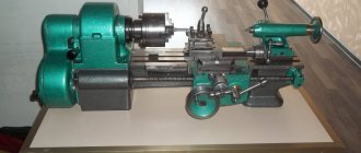
The machine was manufactured in 1950, but how well does the old model cope with the tasks of modern workpiece processing? The 1M63 lathe is a retro model, it amazes modern specialists with its efficiency.
In the post-war period, increased attention was paid to production capacity and improving the quality of processing of metal blanks. The innovative 1M63 machine came to the aid of ordinary, low-efficiency equipment models. The unit developed by Ryazan engineers had unique expanded functionality, which significantly increased work productivity.
Application area
The buyers of the 1M63 screw cutting machine were often machine-building plants with fairly large production volumes. This is due to the fact that the model’s lead screw allows processing of workpieces with a length of 750-10000 mm, depending on the RMC. However, today this screw-cutting lathe is significantly inferior to modern screw-cutting models in terms of productivity and processing accuracy. Purpose: you can sharpen cylindrical and cone-shaped parts, cut threads.
The 1M63 model lathe can be used to work with complex shapes and rounded types of workpieces. An additional purpose is cutting various standard threads. The equipment drawing assumes a very convenient design of the main spindle and the cutter itself; in addition, the following tools can be installed for operation: countersinks, drills, taps and dies. The workpiece itself for subsequent processing can be fixed directly in the chuck or supported by fasteners in the centers.
The main advantages of the machine are attributed to:
- ease of performing any operation;
- uncomplicated design of the machine's key elements;
- the bed of the 1M63 lathe is characterized by sufficient rigidity, and the standards of temperature stability and processing accuracy have also been increased;
- the characteristics of the installation’s engines have high power ratings, which facilitates metal processing;
- the wear resistance of each individual component unit is high;
- thread cutting speed is very high;
- the kinematic diagram is characterized by a certain rigidity, which has a positive effect on the overall performance of the installation;
- The 1M63 package includes electrical and standard mechanical interlocks, which provide maximum safety when performing any operation.
Unit parameters
The technical capabilities of the unit are limited to the following permissible parameters:
- according to GOST, the accuracy of parts processing reaches the “H” indicator;
- the diameter of the workpieces being turned above the support reaches 35 cm, processing above the bed is limited to 63 cm;
- the maximum length of the workpiece reaches 140 cm;
- equipment centers are located at a height of 31.5 cm;
- spindle rotation is maintained at a reduced speed of 18/1800 rpm, this occurs when reverse gear is engaged. The spindle moves forward at a speed of 10/1250.
- the built-in braking system plays the role of a gearbox, this made it possible to select 22 forward processing speeds and 11 reverse processing speeds on the machine.
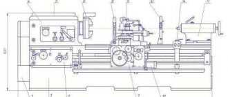
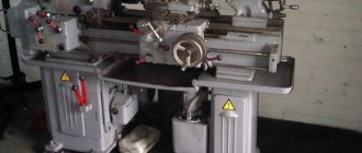
Lathe 1M63
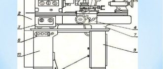
Design Features
The 1M63 has several qualities that distinguish it from other lathes:
- The 1M63 tool holder is designed so that tools made of special alloys and high-speed steel can be used. The tool holder is designed in such a way that it can be adjusted to fit the cutting tool and rotated to the desired angle.
- The 1M63 metal lathe belongs to the class of screw-cutting machines, which are responsible for the ability to carry out work on cutting threads. To do this, a guitar of interchangeable gears is installed. In addition, the gearbox has replaceable gears. By selecting gears, you can change the thread pitch.
- In order for the part to be turned at high speed and at high feed rates, the rigidity of the lower part of the support and the bed was increased.
- The 1M63 screw-cutting lathe is equipped with a special motor and feed box, which make it possible to speed up the movement of the support while turning the workpiece. The feed box also has hardened steel gears.
- When creating the upper part of 1M63, the possibility of movement was also provided. That is why, when installing a standard tool holder, it is possible to turn conical surfaces.
Guitar lathe 1M63
The passport of the 1M63 screw-cutting lathe indicates that the weight varies from 4200-13200 depending on the RMC indicator. Let's also review the main characteristics.
Download the passport (operating instructions) of the 1M63 screw-cutting lathe
A wide range of work performed on turning equipment of this model is ensured by individual design upgrades. Any operation of turning, creating cones and cutting threads is carried out quite easily, without fine scrupulous adjustments. Additional design features of the 1M63 installation are:
- the diameter of the workpieces has been increased to 700 mm;
- the permissible diameter of parts above the caliper is 350 mm;
- the permissible weight of workpieces has been increased, now you can work with parts up to 3.5 tons;
- the diameter of the cylindrical hole in the main spindle is 105 mm;
- there is a function of cross-shaped displacement of the calipers in the longitudinal plane – 5.2, in the transverse plane up to 2 m/minute;
- the power of the power unit was increased to 15 kW;
- The weight of the model is 5750 kg.
Lathe support 1M63
Large dimensions and increased functionality allow the 1M63 model to be installed in large workshops, where the emphasis is on the quantity of products produced. At the same time, the accuracy and efficiency of the machine also remains at a sufficient level.
Adjustment of screw-cutting lathe 1М63М
During the operation of the machine, there is a need to regulate individual components of the machine in order to restore their normal operation.
Adjusting the friction plate clutches of the gearbox (Fig. 25)
Adjustment of friction clutches of machine gearbox 1m63m
If slippage occurs, the friction clutches must be adjusted immediately, otherwise the increased friction will cause the discs to overheat and the clutch may fail. Adjustment of the friction clutches of both forward and reverse strokes is carried out using clamping nuts 1. The clamping nut can be rotated after the protruding hook 2 is recessed into the ring 3. The correctness of the adjustment is determined by the force of engagement of the clutches using the control handle 21 (see Fig. 6).
Access to the clutch is provided through a lockable window in the rear wall of the gearbox housing.
Simultaneously with adjusting the friction clutches, it is necessary to adjust the brake clutch control cam.
The acceleration time of a spindle with a three-jaw chuck Ø 400 mm at 1600 rpm with forward stroke should be 4...6.5 s, with reverse stroke 7...10 s. Checked at idle.
Under these conditions, the braking time should not exceed 10 seconds.
Aligning the spindle axis (Figure 26)
If the parallelism of the spindle axis relative to the frame guides is not correct, loosen all the bolts securing the gearbox to the frame, using screws 1 screwed into block 2, which is installed under the spindle head, align the spindle axis and tighten the fastening bolts.
Installing the tailstock quill axis (Fig. 27)
Transverse displacement of the tailstock is carried out when setting up for turning cones using screws 1, loosening one of them and tightening the other. When installing the tailstock coaxially with the axis of the headstock spindle, align the marks marked on the plates of the headstock body and the bridge at the right end.
Adjusting the tailstock support spring bearings (Fig. 28)
During operation or after repair, it may be necessary to regulate the degree of compression of the cylindrical springs 4 and 5 of the support spring-loaded bearings 6, mounted in the tailstock bridge in order to ensure ease of movement of the tailstock along the frame.
To do this you need:
- loosen the screws securing the headstock;
- Unscrew the top plugs 1 and, using screws 7, move the tailstock 2 along the bridge so as to gain access to the adjusting plugs 3. By turning the plugs, ensure that the headstock can easily move along the frame in the absence of a gap between the guides of the bridge and the bed.
Adjusting the gap in the cross slide guides (Fig. 29)
The gap between the guides of the carriage and the cross slide is adjusted by tightening the click 1 using two screws 2 located at both ends of the slide.
Adjusting the gap in the slide guides of the caliper (Fig. 30)
When a gap appears in the guides of the cutting slide, the wedge 1 is tightened with screw 3, after which the position is fixed with screw 2.
Eliminating the “backlash” of the caliper transverse movement screw (Fig. 31)
Elimination of backlash of a machine screw 1m63m
The “backlash” of the transverse support screw, which occurs when nuts 3 and 4 are worn, can be eliminated by turning worm 2 clockwise, for which it is necessary to first unscrew the locking screw 1. Adjustment is made if the handle lift exceeds 5 divisions of the dial.
Eliminating the “backlash” of the screw for moving the caliper tool slide (Fig. 32)
The “backlash” of the caliper tool slide screw, which occurs when half-nuts 4 and 5 are worn, can be eliminated by tightening screws 3, having previously loosened screws 1. Adjustment is made when the backlash of the handle exceeds 5 dial divisions. The adjustment is made through the threaded hole of the plug of 2 cutting slides, for which it is necessary to unscrew the plug and place the cutting slide in such a position that there is access to the adjusting screws.
Adjusting the axial clearance in the guide of the upper and lower halves of the lead screw nut (Fig. 33)
When a gap appears, the strip 1 is tightened with three screws 2 and secured with locknuts 3.
Adjusting the radial clearance between the lead screw and its nut (Fig. 34)
The amount of radial clearance between the lead screw 2 and the liners of its nut 1 is adjusted by screwing in or unscrewing screw 4 located under the apron. In the adjusted position, screw 4 is fixed with nut 3.
Coordination of the operation of the brake clutch with the operation of mechanical friction clutches (Fig. 3B)
To avoid failure of the electromagnetic brake clutch, it is necessary to check the position of cam 2 relative to the locking ball 1 and the limit switch located in the rear niche of the frame at least once a month.
With the friction clutch shift handle in a fixed middle position, the locking ball 1 and the pusher in the limit switch must be in the middle of their grooves. Regulation is carried out by installing the cam using screw 3.
At the same time, it is necessary to check the reliability of screws 4 and 5.
Adjusting the oil supply to the lead screw (Fig. 36)
Oil is supplied to the lead screw only when the lead screw is operating. To do this, you need to turn throttle 1 to open the gap to the required amount for oil to flow from the manual plunger pump.
Location of fittings for electromagnetic couplings of the apron and their regulation (Fig. 37):
- a brush holder that powers the electromagnetic clutch for the longitudinal movement of the carriage from right to left;
- a brush holder that powers the electromagnetic clutch for the longitudinal movement of the carriage from left to right;
- a brush holder that supplies the electromagnetic clutch for moving the cross slide and the upper support from the worker to the product;
- a brush holder that supplies the electromagnetic clutch for moving the cross slide and upper support from the product to the worker.
If the electromagnetic couplings of the apron fail to operate, it is necessary to turn off the machine and unscrew the brush holder of the faulty coupling.
Check the turned out brush holders for smooth movement of the brush in the holder, check the fit of the brush to the slip ring.
Adjusting the tension of the main drive belts (Fig. 38)
If a sensitive decrease in torque on the spindle is noticed with a normally adjusted friction clutch, the tension of the V-belt drive 2 of the main drive should be adjusted. To do this, it is enough to loosen four bolts 3 and rotate nut 1 to lower the main drive electric motor with plate 4 along the longitudinal grooves.
Secure the engine position by tightening all bolts 3.
Main characteristics
The design of the clutch of the 1M63 lathe, as well as its other elements, complies with the established standards in 1982. The model belongs to accuracy class H and must meet the established standards. The technical specifications are as follows:
- 1M63 spindle bearings support rotation speeds ranging from 10 to 1,250 rpm.
- A lathe can have a very different RMC. During operation, both fixing elements are motionless.
- The model can be used for processing long and non-rigid parts with different RMC values. For this purpose, it is possible to install a steady rest. However, it is worth considering that the steady rest is not supplied. The steady rest for the 1M63 lathe is used to limit the deformation of parts when processing.
- The tool holder is made in a classic style: the tool itself is stationary, only the support moves. The distance between the axis of the centers and the edge of the tool holder is 32 cm. In the manufacture of the tool holder, durable material is used, which eliminates the possibility of deformation of the structure. Adjusting the tool holder allows you to select optimal turning performance.
- The holes in the spindle are 65 mm. The spindle is used to install workpieces with a diameter of 630 mm. A straight rod can be installed and fed as it is turned on the 1M63 screw-cutting lathe in question.
- The tailstock is installed on the screw-cutting lathe in question, and with its power, the rear end is fixed.
- The gearbox allows you to adjust the speed in 22 ranges.
- The support has longitudinal and transverse feed in automatic mode.
- The kinematic mechanism is quite complex. There is a front and back stock. There is a gearbox in the headstock. The tailstock allows you to fix the second end of the part. The position of the tailstock can be changed. Overrunning clutches 1M63 are also used, which are responsible for maintaining the accuracy of operation.
- When considering gearboxes and feeds, we note their high strength and reliability. The maintainability of the boxes makes the 1M63 screw-cutting lathe more attractive.
- The electrical cabinet is located in the headstock, which is confirmed by the drawing of the 1M63 lathe.
- The apron of the 1M63 lathe is controlled using a special switch.
- The characteristics of the replacement wheels allow you to cut inch, metric, modular and pitch threads. The technical potential of the model is quite large. You can install replaceable wheels for turning threads of various types
You should purchase a steady rest to improve the quality of processing when you need to carry out high-precision turning of deformable workpieces. Lunettes can be made from a wide variety of materials. If you do not use a steady rest, a strong feed will lead to deformation of the workpiece. Steady rests can be installed and removed depending on the tasks assigned.
Instructions for the initial start-up of the machine 1M63.01
During the initial start-up of the 1M63.01 machine, it is necessary to check the reliability of grounding and the quality of installation of electrical equipment by external inspection. After inspection, disconnect the power wires of all electric motors at the terminal sets in the control cabinet and connect the machine to the workshop network using the input circuit breaker. Check the operation of all locking devices
- Using manual controls, check the precise operation of magnetic starters and relays.
- Once smooth operation of all electrical devices located in the control cabinet is achieved, connect the previously disconnected wires to the terminal sets.
- By alternately turning on the electric motors of the main drive and quickly moving the caliper, check the correct direction of their rotation.
- After making sure that the electric motors rotate correctly, you can begin testing the machine in operation.
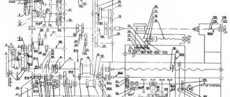
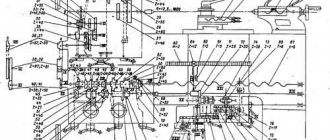
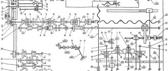
Electrical equipment and kinematic diagram
Kinematic diagram of the 1M63 machine
The 1M63 screw-cutting lathe, the electrical circuit of which has 4 electric motors, also has a detailed description of each node module in its passport. The main motor can operate from a 50 Hz or 60 Hz network. The electrical diagram indicates that the motor has a power of 13 kW.
The operating instructions provide for cooling the system. A large motor is also installed for this purpose. The kinematic diagram indicates the need to supply 22 liters of liquid per minute. Electric motor power 0.12 kW.
The kinematic mechanism is also represented by a motor, which ensures accelerated movement of the caliper. The cutter moves along with the support thanks to the installation of a motor with a power of 1.1 kW.
The kinematic diagram of the 1M63 machine also indicates the presence of four couplings. The 1M63 friction clutch is responsible for the movement of the carriage: longitudinal and transverse passage is carried out during turning, the internal mechanical element allows you to quickly bring the cutting tool. The electromagnetic type of the device allows you to quickly change the position of the carriage. There is a 1M63 direct friction clutch, which is designed to ensure smooth direct feeds in the equipment.
Electrical circuit of the machine 1M63
Electrical equipment of the machine 1M63.01
To ensure high reliability in operation and maintenance of the electrical equipment of the 1M63.01 machine by semi-skilled specialists, all relay-contactor equipment and other electrical equipment have a simple design and have been tested over many years of operation in various conditions.
The electrical equipment of the 1M63.01 machine (with the exception of several devices) is mounted in a control cabinet located on the rear side of the machine.
The electrical equipment of the 1M63.01 machine is designed for connection to a three-phase alternating current network with a solidly grounded or insulated neutral wire.
The electrical connection and the power cables used must comply with regulations. The voltage and frequency in the electrical network must correspond to the data on the machine nameplate. The fuse should be 25A.
Use connecting cables only with the designation H07RN-F.
Electrical connections and repairs must be carried out by qualified electricians.
The electrical connection is made to the terminal blocks in the electrical cabinet at the rear of the machine.
Safety instructions
The 1M63.01 machine must be securely connected to the workshop grounding device (circuit).
The electrical resistance measured between the ground screw and any metal part of the machine that may become live as a result of insulation breakdown should not exceed 0.1 ohm.
IT IS STRICTLY PROHIBITED to work with an open terminal box and control cabinet!
A safety light-signal device is installed in the control cabinet, indicating the presence of voltage between the output terminals of the input circuit breaker and the neutral wire.
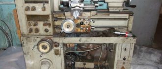
Repair of equipment
Working on any equipment involves both scheduled and complex repairs. Measures to restore the functionality of individual mechanisms are required for the 1M63 model quite rarely. But a gradual loss of stability and loosening of individual structural components leads to a decrease in the accuracy of operations and a decrease in processing speed.
To carry out a comprehensive repair from the manufacturer, the customer must send the following documents together with the machine: a technical passport of the installation, special reports of previous technical inspections and a statement that reflects information about the assembly node modules.