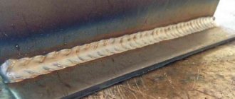
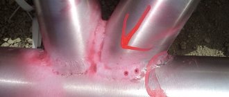
A welded connection is a permanent connection obtained as a result of the metal being melted at the junction of the parts and the resulting space being filled with molten filler metal. The resulting mixture of metals, when solidified, forms a welding seam, which, due to its mechanical properties (tensile strength), can withstand greater loads than the metals being welded.
Welding can be (Fig. 1) electric arc, gas flame, electric contact, etc.
Rice. 1. Types of welding: a – arc; b – gas; c – in a shielding gas environment: 1 – electric arc, 2 – consumable electrode, 3 – electrode holder, 4 – filler material, 5 – welding torch, 6 – flame, 7 – electrode, 8 – shielding gas, 9 – torch nozzle
In this article:
In addition, GOST 16037-80 describes the types of butt welds in pipes. They can be connected end to end in a straight line or with a slope. The document describes the technology when it is necessary to make a connection with a bend or branch. Due to the hollow structure inside the pipe, such connections are not similar to others and are placed in a separate category so that the welder does not get confused about the types of butt welds during assembly.
If the parts to be welded are very narrow, for example, two reinforcements need to be connected at the ends, then such welds are called end or butt welds. They are separately described in GOST 14098-2014. The reinforcement can also be welded crosswise or overlapped.
Types of spatial positions of welds
All of the listed types of welds can be made in the following spatial positions:
- Bottom
- the product is located on the floor, table. The liquid metal does not flow anywhere; the slag has to be forcibly removed with an electrode. One of the easiest spatial positions for beginners. - Bottom "boat"
- suitable for corner and T-joints. The joint is positioned so that the molten metal reaches both walls of the joint equally. If the product is slightly tilted along the longitudinal axis of the seam, the liquid slag will drain spontaneously without interfering with the weld pool. - Vertical
- manual arc welding is carried out from the bottom up with an intermittent arc, otherwise the liquid metal flows down under the influence of gravity. Semi-automatic and argon arc welding is performed from top to bottom. This is a more complex spatial position for the welder, the implementation of which requires a certain skill. - The ceiling position
is the most difficult position, since liquid metal and slag constantly drip down, and you have to cook with your head bent up. The neck and arm get tired quickly.
There are also horizontal seams on a vertical surface. Their difficulty lies in the fact that the metal flows more onto the lower side, while undercuts and lack of penetration remain at the top. For high-quality execution, it is necessary to reduce the current strength, and sometimes conduct the seam with an intermittent arc.
Preparation for welding
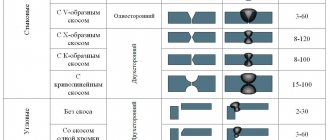
In order for the seam to be of high quality, proper preparation of the sides for welding is required. If the metal is thicker than 5 mm, one-sided edge cutting is performed with an angle of 45º. With a plate thickness of 10 mm, cutting is required on both sides. Without such preparation, it will not be possible to melt the metal deeply and the connection will be superficial. Based on this, the types of chamfers are:
- V-shaped;
- Y-shaped;
- X-shaped;
- U-shaped.
Rusty metal leads to unstable arc combustion and “spitting” of slag. The sides in the welding zone (at least 20 mm from the connection line) must be cleaned of rust, traces of paint, and oil. If you have to weld thin metal 1-1.5 mm end-to-end, use a copper substrate to prevent burns.
To prevent the workpiece from moving during welding, tacks are first made, and they must be on both sides. This applies to all types of connections.
How the parts are connected
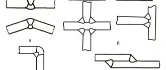
The technology for the production of welding joints, including their types, dimensions of the main elements and their symbols in the drawings, is established by GOST 5264-80. To correctly read a drawing intended for welding a structure, you need to familiarize yourself with this standard.
In accordance with GOST, when performing welding work, the following types of connections can be used:
- butt;
- corner;
- T-bars;
- overlap
It is worth talking about each of them separately, since the choice of welding joint and preparation of the edges of the workpieces directly affect the quality of the seam.
Butt
This welding joint is characterized by the adjacency of the side surfaces of the parts being welded, located in the same plane.
There are varieties of this welding operation. The work can be performed without preparing the surfaces to be joined. When welding relatively thin sheet material, its edges can be pre-flanged, that is, bent at an angle of 90 °C.
For thicker workpieces, to ensure complete penetration of the material through thickness, bevel the edges on one or both sides. The bevel shape of the edges can be straight or curved.
To hold the weld pool in the seam area, a flat lining is sometimes placed under the sheet blanks being welded, which is removed after the work is completed.
The seam itself when making a butt joint can be one-sided or two-sided.
Corner
This connection is applied to parts that are not in the same plane, the edges of which are located at a certain angle relative to each other. Such connections are also made with or without preliminary surface preparation.
Preparation consists of beveling the edges to be joined in different ways; one of the planes can be beaded. Welds, depending on design requirements, are single-sided or double-sided.
T-bar
With a T-joint, the edge of one of the parts being welded is attached to the surface of another part at an angle of 90°. Thus, the cross-section of the connection is shaped like the letter “T”.
To improve the quality of the connection, one-sided or two-sided bevels of the edges of the attached element are used. Those parts are processed whose ends are welded to the planes of other parts.
For better welding of the metal, when fastening parts, usually ensure that there is a small gap between them. The gap size is 2 – 3 mm.
In general, for each specific procedure, a flow chart of the operation must be drawn up, taking into account all the requirements of the design of the assembled structure.
overlap
Parts connected with an overlap are superimposed on one another, while being in parallel planes. Seams are made on one or both sides.
In this case, it makes no sense to bevel the edges, since the end sections and planes of the parts to be joined form a concave angle that holds the weld pool well and makes it possible to make a strong seam.
Classification of welds
In addition to the type of connection and position of the seam in space, joints are classified according to the technique of making the seam and additional characteristics.
Electrode position during the welding process
Welding can be carried out with a coated electrode, holding it relative to the plane of the product at different angles:
. The welder tilts the electrode towards himself by 30-60º, and leads the seam away from himself. The weld pool moves ahead of the electrode, and the slag reliably covers the molten metal. The technique is applicable when welding thin sheets, as it reduces heat input.
. The welder tilts the electrode towards himself at an angle of 30-60º and the weld leads towards himself. The slag is displaced by arc pressure and the weld pool is better controlled. Penetration due to increased heat input is deeper. Suitable for face welds that require a beautiful appearance, as well as when welding thick parts.
. It is used only when welding in hard-to-reach places where it is impossible to crawl in any other way. Not a very convenient method, since it limits the visibility of the weld pool.
Electrode movements
The appearance of the seam largely depends on the movement of the electrode. On connections without a gap, usually no oscillatory movements are required - the electrode is guided smoothly, ensuring fine scales and a uniform width. It is only important to choose the right speed so that the edges have time to melt and the base metal does not burn through. To fill wide seams, welders use transverse oscillatory movements in the form of:
By configuration
The joining line determines the future configuration of the weld, which is possible:
By degree of convexity
The degree of convexity is called the leg of the weld. Based on the parameters of the applied roller, the legs can be:
The greater the height of the roller, the stronger the seam and the more difficult it is to break it.
By length
If increased strength or tightness of the connection is required, then continuous welds are made. This requires more time and increased consumption of filler metal. When the load on the structure is low, intermittent seams 2-3 cm long are acceptable. This ensures the integrity of the product, reduces welding time and saves semi-automatic electrodes/wire.
By number of passes
For metal sheets of 2-4 mm, one pass is enough to weld the joint. Thicker sides require edge trimming and multiple passes. Such seams are called two-pass, three-pass, multi-pass.
By type of welding
Welding connections are possible using:
Electric contact welding
Types of resistance welding are spot, seam and butt welding. In spot and seam electric welding, an electric current is passed through electrodes that compress sheets laid overlapping, and in butt welding - through sheets laid end-to-end. During the welding process, the electrode moves along the surface of the sheets being joined. Under the electrode, at the place where it passes, the current passing through the metal heats it, and the sheets are welded.
These types of welding are very economical and productive; they are used to join sheet products (Fig. 2).
Rice. 2. Schemes of electric contact welding: a – spot, b – seam
Seam defects
The main types of defects in welded joints are:
- Lack of penetration
- formed when the current is weak, the arc is drawn quickly, the seam is placed past the joining line, when the welder cannot clearly see the joint in the mask. - Nodules
- bumps, uneven waves, “snot” of frozen metal. Appear at vertical and ceiling seams due to improper execution technique. In the lower position, they are possible due to the uneven speed of the seam. - Undercuts
are snatched parts from the base metal on the side border of the seam. They occur when the electrode moves incorrectly and the current increases. - Pores
are possible when welding contaminated metal, when foreign particles burn and their gas fraction bursts out. Pores appear when the weld pool is insufficiently protected (it is necessary to increase the gas supply). - Craters
are a hole at the end of a seam that compromises the tightness of the joint. Formed when the arc is abruptly interrupted by argon welding. In the case of RDS, craters appear due to the interference of slag. - Cracks
- occur when the joint is cooled sharply (immediately pour water into the seam to cool and continue assembling the structure). When welding cast iron, cracks form due to uneven heating of the product.
Requirements for welds
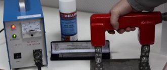
The quality of welds is assessed by non-destructive and destructive testing methods. The first includes ultrasound and x-ray scanning of the seams. Such checks are carried out at particularly critical joints subject to high loads.
During destructive testing, seam samples are checked for tension and fracture, based on which the following is assessed:
The required level of each characteristic is specified in the welding drawings.
Calculations
When designing various structures, all technical parameters, including the use of a certain type of welding, as well as the choice of method for connecting parts, are carried out on the basis of preliminary calculations. First of all, the structure is calculated for strength .
The initial data for this is the modeling of the loads to which the structure will be subjected during operation. Based on this, the material and method of connecting individual elements are selected. Calculation methods for each type of welded joint are standardized and unified.
When carrying out calculations for the strength of welds, the nature, directions and magnitudes of loads on the joint areas are determined. The obtained values are compared with the maximum permissible values for the materials used.
Based on their comparison, a conclusion is made about the safety margin of the structure. This calculation is made many times, separately for each connection option, type of welding used and structural material. Only with correct calculation can a reliable connection be obtained.
