Guides are an important part in the design of a milling machine. Many craftsmen can make CNC guides with their own hands; most practitioners have experience working at home.
When planning home furniture production, it is necessary to maintain precision in design. Therefore, many masters mastering it need high-quality equipment. A special woodworking mechanism will make work easier and allow you to create high-quality products in a short time.
To ensure that products are highly accurate but meet modern specifications, CNC models are used.
Computer numerical control
Numerical program control provides such an opportunity, but not every entrepreneur can buy it. It is for this reason that there is a need to manufacture a home-made unit, for the construction of which parts of our own production are used.
The main parts of milling machines designed for processing a particular material are guides. They are ball or roller bearings whose purpose is to move the carriage. Their goal is to speed up, simplify and add precision to production.
Shaft and its types
It is worth giving a brief description of the other types.
- The spline shaft is characterized by the presence of a special track for the bushing balls. Characterized by greater rigidity and wear resistance, compared to a conventional shaft, it is suitable for mechanisms in which it is desirable to install guides at the ends. They are used extremely rarely in the design of machine tools due to their high cost.
- The shaft on a support in the form of cylindrical rails of a linear type does not allow sagging under load and its own weight. It is mounted on the frame, securely fixing it. Despite the disadvantages, expressed in the presence of large play in the bushings and their short service life, cylindrical rails have a large load capacity. Different from linear bearings, the carriage reacts differently to the degree of load. A small CNC machine that has a heavy spindle has the potential for reduced accuracy.
- The purpose of profile rail guides is greater accuracy. They are also attached to the frame. Thanks to special raceways, the loads on the carriage are distributed evenly over the surface, and the contact profile of the ball to the rail is an arc. Among the advantages are the presence of good load capacity and wear resistance, and backlash is minimized. The difficulties of producing such rails have a negative impact on pricing; they are expensive. This especially applies to guides supplied by well-known brands whose machines are numerically controlled.
- Roller rails have flat raceways, and in the support module, in place of the balls, rollers are installed that improve all the parameters of the guide. They are used in machines that mill ferrous metals, steel and stone.
- Dovetail is chosen for industrial metalworking equipment if increased fastening rigidity is required. In guides of this type, flat surfaces slide with a maximum contact area. They are made in the form of a monolith with a frame. Due to the complexity and labor-intensive manufacturing and repair process, these guides are therefore not accepted by the hobby machine tool industry.
This solution for a homemade linear bushing bearing or our hands is not for boredom. Part 1.
Subscribe to the author
Follow the author if you like his publications. Then you will receive notifications about his new posts.
You can always unsubscribe from notifications in the author's profile.
The article applies to printers:
Hello gentlemen 3D guys!
What prompted you to write? Yes, I just wanted to voice my thoughts out loud, consult and confer.
Like many of those present here, the journey of 3d_printing for me began with Rep-Strap.
I put together at least a printer and sculpt... for myself, for friends, I even bought some things.
Anyway. not about that.
In general, the problem is like many others with linear bearings and guides.
Guides. COMPLETE. I work as an IT specialist, so I've had a lot of inkjet experiences.
I bought stainless steel guides with diameters of 8mm, 10mm, 12mm. and corresponding medicinal products.
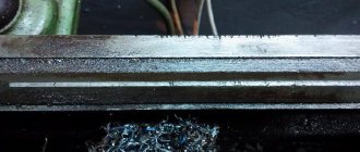
Everything seems to be working, only some play or grooves are forming on the axles.
Previously, carriages rode on caprolon bushings, which sometimes jammed.
I agree that in some places my handiwork was to blame, and in general the first damn thing was lumpy).
And also so that now, and free of charge, (those DADOM) (c) Owl), and so that it is printed quickly, efficiently, beautifully!)
Opinions also differ about ABS bushings.
But I liked it and decided to experiment with it.
In the video, the guy used Teflon tubes.
Print a clip from ABS, and there will be pieces of trimmer line as roller balls.
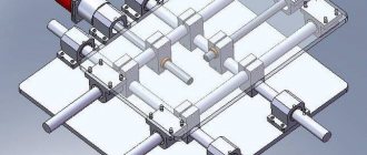
I won’t explain it with my fingers, I’ll show you in FreeCade.
And then Ostap suffered. And if like this:
In general, you can fantasize a lot.
Today is Friday and the printer is at work. Here's what I managed to implement today:
The ease of movement can be adjusted by the number of nylon inserts.
The downside is the appearance of backlash, but here apparently we need to look for a middle ground.
Nylon inserts are very reluctant to fit into the grooves.
This is actually what I have managed so far. After the weekend I will print the rest of the bushings and the mounting for them. They will go to the table.
Types of linear guides
Linear guides come in two types:
- with ball circulation;
- with circulation of rollers.
Ball guides are made in two, four and six rows. They are miniature, suitable for use in limited installation space. Linear guides are manufactured with different drives. Among them, the most common are a toothed belt or a ball screw drive (ball screw drive).
Roller guides are made in the form of cylindrical guides and guides with a flat cage.
All guides must have the following main properties:
- low friction;
- high efficiency;
- smooth linear movement;
- ability to maintain operating parameters.
Installation of rail guides
It is important to know that linear rail guides are subject to force and torque. For them, the following values must be determined: permissible static moment and load capacity, which are calculated using formulas. When calculating the nominal life of ball and roller guides, it is necessary to use different formulas.
With a constant stroke length and frequency of movements, the service life is expressed in terms of time. With compact mounting dimensions, profile rail guides have a high load capacity. Installed in various types of machines or other equipment, they are mounted in two different ways: as a horizontal rail and as a side mounting method.
Since the set consists of two parallel rails, the first rail is located on the base side, and the other on the adjustable side.
When working with large shock loads and vibrations, installing additional side parts - a side pressure plate, set tension screws, a conical wedge - helps eliminate them.
Installation of additional clamping parts when working with low loads and low speeds of movement is not necessary.
Shaft and its types
It is worth giving a brief description of the other types.
- The spline shaft is characterized by the presence of a special track for the bushing balls. Characterized by greater rigidity and wear resistance, compared to a conventional shaft, it is suitable for mechanisms in which it is desirable to install guides at the ends. They are used extremely rarely in the design of machine tools due to their high cost.
- The shaft on a support in the form of cylindrical rails of a linear type does not allow sagging under load and its own weight. It is mounted on the frame, securely fixing it. Despite the disadvantages, expressed in the presence of large play in the bushings and their short service life, cylindrical rails have a large load capacity. Different from linear bearings, the carriage reacts differently to the degree of load. A small CNC machine that has a heavy spindle has the potential for reduced accuracy.
- The purpose of profile rail guides is greater accuracy. They are also attached to the frame. Thanks to special raceways, the loads on the carriage are distributed evenly over the surface, and the contact profile of the ball to the rail is an arc. Among the advantages are the presence of good load capacity and wear resistance, and backlash is minimized. The difficulties of producing such rails have a negative impact on pricing; they are expensive. This especially applies to guides supplied by well-known brands whose machines are numerically controlled.
- Roller rails have flat raceways, and in the support module, in place of the balls, rollers are installed that improve all the parameters of the guide. They are used in machines that mill ferrous metals, steel and stone.
- Dovetail is chosen for industrial metalworking equipment if increased fastening rigidity is required. In guides of this type, flat surfaces slide with a maximum contact area. They are made in the form of a monolith with a frame. Due to the complexity and labor-intensive manufacturing and repair process, these guides are therefore not accepted by the hobby machine tool industry.
Do-it-yourself production of guides for CNC
Guides are an important part in the design of a milling machine.
Many craftsmen can make CNC guides with their own hands; most practitioners have experience working at home. When planning home furniture production, it is necessary to maintain precision in design. Therefore, many masters mastering it need high-quality equipment. A special woodworking mechanism will make work easier and allow you to create high-quality products in a short time.
To ensure that products are highly accurate but meet modern specifications, CNC models are used.
Numerical program control provides such an opportunity, but not every entrepreneur can buy it. It is for this reason that there is a need to manufacture a home-made unit, for the construction of which parts of our own production are used.
The main parts of milling machines designed for processing a particular material are guides. They are ball or roller bearings whose purpose is to move the carriage. Their goal is to speed up, simplify and add precision to production.
Rolling guides
They are designed using rolling bearings.
Linear bearings have more play than the carriage of rail guides; they are less loaded. But it has a number of disadvantages:
- low level of carrying capacity;
- fragility;
- manufacturing with significant play;
- sensitive to the effects of dust and chips on the shaft.
The material for the production of bushings is bronze, brass, caprolon. If tolerances are maintained, bronze plain bearings are as good as rolling bearings. From time to time, if the plain bearing is worn out, it is adjusted to eliminate the gaps. Therefore, the linear bushing is preferred due to its availability and interchangeability.
DIY sliding bushing
homemade plain bearings
Re: homemade plain bearings
karabas2011 » Jun 02, 2013, 12:13
Re: homemade plain bearings
Myp » 02 Jun 2013, 21:54
Re: homemade plain bearings
Radus » 03 Jun 2013, 08:46
Re: homemade plain bearings
Myp » 03 Jun 2013, 09:58
Linear ones are not slipping at all; linear ones, as you say, stick.
Sliding bearings are simply flat bronze bushings (sometimes coated with Teflon), without balls, they slide perfectly smoothly.
Re: homemade plain bearings
karabas2011 » 07 Jun 2013, 17:03
Re: homemade plain bearings
by andreykyz » Jun 23, 2013 1:47 pm
Somebody knows. Such bushings are suitable as linear plain bearings. Cargo 140555 Starter bushing for 10mm shafts. Or do you need exactly 10mm ID.
Re: homemade plain bearings
avr123.nm.ru » June 23, 2013, 15:03
Re: homemade plain bearings
Myp » June 23, 2013, 3:42 pm
oh, what interesting bushings they have, I found 16 mm bushings in their catalog at Cargo, just what I was looking for to replace the plastic ones, and the price is reasonable and they sell them at Exist, I ordered several different ones, I’ll see which one is better.
It’s hard to say about 3 acres, for this you need to accurately measure the shaft itself, there is a high chance that the diameter of the shaft itself can easily vary by 3 acres. I would advise taking several bushings, exactly 10 and 10.03 and try on a specific shaft to see how it goes.
Re: homemade plain bearings
by andreykyz » Jun 23, 2013 6:46 pm
hmm. I think I will do so.
Added after 12 minutes 31 seconds:
Re: homemade plain bearings
ylvov » Jun 27, 2013 05:45
These are the bearings they made for me from fluoroplastic. Shaft 10mm 150 RUR per piece. Moving from a dead point is like moving on ice.
Re: homemade plain bearings
Myp » June 27, 2013, 2:30 pm
and I received my bronze ones
1. CARGO and IKA bushings look no different; they have a rough inner surface; the bushings are pressed, without a groove in diameter. When put on the shaft, the roughness is erased and the bushing fits tightly. If you remove the bushing, contact spots are visible inside, the bushing has worn out and began to shine. so you need to cut it and make a tightening mechanism, otherwise after grinding it will start to dangle. the difference in diameter of 0.03 is not noticeable.
Linear motion technique. Mechanical components.
Detailed descriptions, catalogs and engineering information are located within individual subsections. If necessary, our specialists will help you select the most suitable products for your task.
Guiding mechanisms:
- High load capacity
- High accuracy
- Self-centering
- Compactness
- In stock
Drive mechanisms and devices:
- High efficiency
- High accuracy
- High load capacity
- In stock
Electromechanical linear actuators
- Actions
- Search for spare parts from other manufacturers
- Go to catalog library
- EcoPRO products - inexpensive solutions for professionals
- Products sorted by category
- Guides
- Ball profile rail guides
- Roller profile rail guides
- Ball bushings
- Linear blocks
- Precision round shafts and bearings
- Spline shafts
- Precision rail guides and tables based on them
- Guide protection systems
- Lubricant for linear guides and ball screws
- Drive technology
- Ball Screws, Roller Screws, Supports
- Racks and Gears
- Actuators and positioning systems
- Coordinate tables
- Linear modules
- Electromechanical Rod Linear Actuators
- Other product groups
- Electric drives and electronics
- Industrial pneumatics
- Ready-made systems
- Other products
LLC "Aketon"
Official distributor of NB in Russia and the former CIS countries. Direct deliveries of industrial goods and components from Japan, Europe, America.
Copyright 2006-2020 Aketon LLC, All rights reserved.
105523, Russia, Moscow, Shchelkovskoe highway, 100, bldg. 6, office 202 (diagram)
Igrek
Let's move on.
The cross beam on which the Y-axis rails will be installed is 510 mm long. For the purpose of unification, we will make it from the same aluminum box 80x40x4 mm. We will place the rails directly on the ends of the beam.
A large rectangular hole on the wide edge of the profile will accommodate the motor axis with a gear mounted on it. On the opposite side of the beam there will be a carriage Z. That is. the beam should pass as if through the Y carriage. To do this, we will put two identical parts on ball blocks, made from sections of a standard aluminum channel 60x40x5 mm.
We will carry out the wiring of the toothed belt in exactly the same way as along the X axis, only we will make devices for fastening and tensioning the belt at the corners.
The belt is well protected from chips and dirt. At the bottom of the profile (inside) there will be a cable loop from the Y and Z motors. All that remains is to put the plugs on the ends of the beam and that’s it.
On the front side (from the side of the Z carriage) the beam has no holes, which is very good, because This is where the chips fly. As you can see, the beam with the Y carriage turned out to be very simple.
Device manufacturing algorithm
First you need to measure the diameter of the tool. Before doing this, be sure to remove the nut that holds the drill. Then apply the obtained data to the neck of the bottle and cut out a circle. For safety and convenience, you can also sand the edges of the bottle. Next, you need to insert the cap into the bottle until it fits completely and glue it with glue. This device will be very primitive and its design features will not allow the instrument to be moved vertically. But it is very cheap and very easy to manufacture.
There are also more complicated ways. To implement this we need a smooth wooden board, metal rods and springs.
The first step is also to take measurements. The next step is to make wooden parts. Make two rounded rectangles and make holes in them. The first will be for the instrument itself.
And others must be placed in the corners of a wooden rectangle. We place metal rods in them, they will serve to move the drill vertically. We put springs on the rods and fix the mechanism with glue.
This device is already more functional, because it allows you to move the tool vertically.
Shaft and its types
It is worth giving a brief description of the other types.
- The spline shaft is characterized by the presence of a special track for the bushing balls. Characterized by greater rigidity and wear resistance, compared to a conventional shaft, it is suitable for mechanisms in which it is desirable to install guides at the ends. They are used extremely rarely in the design of machine tools due to their high cost.
- The shaft on a support in the form of cylindrical rails of a linear type does not allow sagging under load and its own weight. It is mounted on the frame, securely fixing it. Despite the disadvantages, expressed in the presence of large play in the bushings and their short service life, cylindrical rails have a large load capacity. Different from linear bearings, the carriage reacts differently to the degree of load. A small CNC machine that has a heavy spindle has the potential for reduced accuracy.
Linear guides for CNC machines
What makes up a linear motion system? This is a combination of gear and linear guides.
Linear guides for CNC are linear bearings, guide bushings, shafts. The guides themselves must solve three main tasks:
- be a support for completing the machine;
- with minimal friction, with the required accuracy along a given trajectory, ensure the movement of machine parts;
- accept the loads arising during the work process.
Linear guides are divided depending on the method of attachment to the machine. These are guides that provide full support - the method of attachment to the frame along the entire length of the guides, and partial support - the method of end attachment.
Fully supported rails have a higher load capacity than partially supported rails. Sometimes there are options when linear guides are installed along the axes - both with full and partial fixation.
Representatives of this group are linear cylindrical guides. They make it possible to use several types of cylindrical guides:
- polished guide shafts - the most common (high availability, ease of installation);
- splined shafts – high wear resistance and rigidity, the ability to accept torsional forces from the bushing. Used for end mounting of guides;
- the shafts on the support are cylindrical rails. They are used as direct attachment to the machine.
Installation procedure
Installation of rails (Hiwin and other brands)
Before installing the guide, clean the supporting surface from burrs and dust. Note. Because the guide is coated with anti-rust oil, before using the guide, remove the oil from the base surface by wiping it with absorption oil. After removing the anti-corrosion oil, the base surface remains unprotected from corrosion
It is recommended to coat it with low viscosity spindle oil. Carefully place the rail on the support surface and temporarily secure it with bolts so that the rail is lightly pressed (align the mark on the rail with the side reference surface of the support). Note. In order for the installation of rail guides to proceed correctly, at this stage the guide must be secured
Clean bolts should be used to secure the guide. When installing bolts into rail mounting holes, check that the holes are not misaligned. Forcibly tightening a bolt in an offset hole may degrade the guide's accuracy.
Tighten the rail mounting screws in order to a torque sufficient to press the rail firmly against the side support surface. Tighten the mounting bolts to the specified torque using a torque wrench (see Table 1) Note. To ensure consistent accuracy when tightening the rail mounting screws, tighten them in order from the middle to the ends of the rail.
Install the second rail in the same way. This completes the installation of the rails. Drive the plugs into the bolt holes on the top surface of each rail so that the plugs are flush with the top surface of the rail.
Installation of carriages
Carefully place the table on the carriages and temporarily secure it with the mounting bolts. Press the carriages on the main rail side to the side base surface of the table using the locking bolts and install the table in place. Fully tighten the installation bolts on the main and auxiliary sides. This completes the installation
Note To secure the table evenly. tighten the installation bolts diagonally
This method saves time and ensures the straightness of the rail, and also avoids machining of the locating pins, which significantly reduces the labor intensity of installation.
Example of installing a guide when the main rail does not have mounting screws
- Main Rail Installation After temporarily tightening the installation bolts, press the rail firmly against the side base surface at the location of each installation bolt using a small vise, and then fully tighten each bolt. Tightening is carried out in order from one end of the rail to the other.
- Installation of the auxiliary rail To install the auxiliary rail in parallel with the main one, which is already correctly installed, we recommend using the methods described below. Using a Ruler Place the rulers between the two rails parallel to the side reference surface of the main rail using an indicator head. Then tighten the installation bolts in order while maintaining the straightness of the auxiliary rail, using the indicator head and ruler as a reference.
Using Parallel Table Edges Secure the two carriages to the main rail using a table (or temporary measuring table), and temporarily mount the rail and carriage to the auxiliary rail using a table. Place the indicator head on the side of the auxiliary rail carriage. In this case, the head holder is fixed on top of the table. Then tighten the bolts in order, keeping the auxiliary rail parallel by moving the table toward the end of the rail.
Installing the Sub Rail on the Main Rail Place the table on the carriages of the properly installed main rail and temporarily secure the sub rail, then fully tighten the installation bolts of the two carriages on the main rail and one of the two carriages on the sub. Fully tighten the bolts on the auxiliary rail in order when temporarily securing the second carriage to the auxiliary rail
Using a conductor Using a device similar to that shown in Fig. below to ensure parallelism of the base surface on the auxiliary side relative to the side base surface on the main side is carried out from the end of the rail in the direction of travel in accordance with the pitch of the rail. At the same time, the bolts are fully tightened in the correct order.
Ready!
The installation of HIWIN rails (or the installation of other brand rails) is complete.
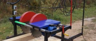
Homemade tabletop mini sawmill
A hand-held circular saw is a must-have tool in the home workshop of a self-respecting owner. To work successfully, it must have a circular saw guide bar. Saw blades are of considerable importance; the quality and accuracy of cutting depends on their thickness and the size of the teeth. The smaller the tooth, the cleaner the surface being processed will be.
A well-equipped workshop has hand-held power tools that have a circular saw guide bar, made and set up for successful work. As well as a special connection for a vacuum cleaner and bags or containers for sawdust. This is a very practical solution, because during long sawing you won’t have to stop every minute to clean the work area. This saw is produced by Bosch for professionals. In addition, it has the ability to adjust the angle of deviation from the vertical and the cutting depth.
Choosing the right tool
Before purchasing, you should make sure that the selected tool provides the required cutting depth vertically and at an angle. An additional aspect that can make normal operation easier is the length of the cable. If conditions are not favorable for using an extension cord, you should choose a saw with a long cord.
The saws offered by well-known manufacturers are equipped with a device for easy replacement of discs, which further simplifies the work. This is an excellent electric tool that can be used for minor repairs around the house or garden.
Preparing materials and tools
Here are the materials that were used:
- plywood 122 x 244 cm, thickness 21 mm;
- wood glue;
- mortise nuts;
- fast acting epoxy resin;
- water-based polyurethane;
- walnut paint;
- bolts and nuts.
The following tools were also used:
- a circular saw;
- electric jigsaw;
- milling cutter;
- cordless drill;
- groove cutter;
- Sander;
- sandpaper;
- hand jigsaw;
- clamps, clips;
- countersink drill.
Linear Motion Modules
Recently, in connection with the development of automation, the use of linear motion modules, which consist of:
- durable supporting profile;
- precise guiding system;
- durable drive mechanism;
- Servomotor with easy control.
In such a modular component, guides with both ball bearings and roller bearings are used. The working drive is carried out using a linear motor, toothed belt or ball screw mechanism.
Linear tables have also found their application, used when it is necessary to move large masses along axes. Due to their dimensions, they absorb large moment loads. Linear tables use:
- linear motion bushings;
- guides with ball circulation.
Installation technology
How to install the roller guide correctly? The installation diagram depends on the mounting method.
Installing side roller guides
How to assemble and install a roller guide on the side of a drawer? The work process is as follows:
- on the side surface the location of the guide bar and the place of its fixation are marked;
- holes for fastenings are drilled;
- the guide is fixed. How to attach the system? For fixing, self-tapping screws (screws) supplied in the kit are used;
Fixing the guide on the side
- According to a similar scheme, the second guide strip is installed on the furniture frame;
Fixing the guide on the furniture frame
- The two parts of the guides fit together.
Connection of sliding system slats
How to install a drawer on roller-type guides, watch the video.
https://youtube.com/watch?v=rTqJyoESEM0
Installing Hidden Roller Guides
To install a hidden guide, you must:
- according to the attached diagram, make calculations and determine the installation locations of the retaining clamps;
Location of holes for mounting guides
- install the clamps, securing them with self-tapping screws;
- insert and secure the guide strips into the clamps;
Fastening the guides
- install the bases on the frame and connect the parts of the system to each other.
Using similar schemes, you can install guides for pull-out shelves in a wardrobe, cabinet or computer table shelf.
Polished shafts
They are characterized by affordability and ease of installation, which reduces repair costs. They are not recommended for use as guides for moving tables whose flow exceeds 1 m, since fastening to the frame at two points leads to sagging under loads. At the same time, they are suitable for moving the spindle along the Z axis, provided that the spindle is not loaded (engraving, cutting thin sheet metal, wood carving, etc.) and is balanced by a counterweight.
Flaws:
- when using rolling bearings, pressure from the ball is applied at one point, and over time a groove is pressed at this point;
- increased sensitivity to chips and dust;
- impossibility of fitting the bearing to the shaft and creating preload.
However, these disadvantages are offset by the low cost and ease of replacing the shaft, and the problem of dust and shavings in wood and stone processing workshops is solved by installing a hood with a socket directly in the work area.
Main functional purpose
Various types of sliding door guides must ensure the free closing and opening of sliding doors, regardless of whether they are interior doors or cabinet doors. The basis of any design is the rails along which the doors move horizontally using rollers.
Additional accessories include:
- roller hangers or supports;
- profile seals and plugs;
- clamps;
- small fittings;
- additional devices, the availability of which depends on the specific choice of rollers and guides.
- "SLIDER-Volkhovets",
- "Framir"
- "Herkules" or "Rollan".
So are imported ones, the price of which is quite high:
- "Raumplus"
- "Francco"
- "Archie"
- "Hangroller"
DIY guides for machine tools
Mechanical processing of any material primarily implies precision and productivity.
Regardless of the type and purpose of the machine, there are basic elements whose parameters cannot be neglected.
The basic component for a metal-cutting, woodworking or plastic processing device is guides that ensure error-free and cyclical processing.
What types of guides are there?
Any machine is based on the precision of processing, which is provided by guide rods. You have to make working units with your own hands, but there are some that you can’t make yourself; only factory-made parts are suitable.
For example, it is unlikely that it will be possible to manufacture the working part of a milling machine, just like with a drilling or turning machine. Therefore, you have to use ready-made solutions - drills, drives, engravers or electric jigsaws. With guides, the situation is simpler, since their characteristics and appearance directly depend on the purpose of the unit.
Almost all of them, used in factory and home-made structures, are of only two types - sliding and rolling. According to the principle of bearings, their method of operation is clear - some are based on sliding, others use rolling bearings in their design.
For low-power equipment that does not require precision and performance, the sliding principle is used. Basically, such parts are used by desktop drilling and turning units, as well as woodworking units. There are also subspecies, but let’s look at those that are easiest to make with your own hands from what is on sale.
Guides for CNC machine
CNC machining centers for small-scale and home use are an expensive thing and not everyone can afford to buy a format boring or CNC lathe, but you can easily make a device with your own hands that is decent in terms of processing quality and cleanliness of the cut. Let's look at several designs, but first we'll look at the factory-made parts to understand the basic principles of operation.
All guides for programmable machines are of circular motion or linear type, this depends on the trajectory along which the moving unit moves in coordinates. We will consider only linear ones, as they are the most popular among DIYers, and there is no particular need for the use of circular devices.
CNC machines from furniture rods
An excellent option when you need to achieve thorough processing, especially in woodworking machines for the production of furniture in small batches, in belt sanding machines, milling machines based on a ready-made low-power milling machine. Furniture parts are inexpensive, although they have a shorter service life than similar sliding elements from printers or typewriters.
An example of using furniture rods on a format boring machine is shown in the photo. It is clear that the dimensions of the bed and movable table are adjusted depending on the purpose.
However, if you use ball-type furniture on a drilling machine, there will be no demolition, since the load and frequency of work on a router or drilling machine are significantly different from the loads on a format-cutting machine.
There is always a way out, and based on the examples given, it is quite possible to select sliding guides for your CNC machine with the desired parameters. Good luck with your work!
angor58
Compacted wood friction parts
Bearings with wooden bushings and inserts have been in use for many centuries. Back in the Renaissance, Leonardo da Vinci developed designs for similar bearings, which are still used in the mechanisms of water mills, lifting gates, grinding wheel supports, and others.
The manufacture of parts for sliding friction units, or, in other words, bushings and bushings for sliding bearings, is one of the areas of use of wood modified by compaction.
Wood waste is used as a raw material for the manufacture of compacted wood blanks, which inevitably accumulate as a result of production processes not only in woodworking, but also in metalworking enterprises. When organizing fairly large-scale production, the wood of young thin-sized soft hardwood trees with a diameter close to the diameter of rough blanks (mainly in the form of poles) can be used as raw material. Wood aged 8-15 years is more elastic and pliable when compressed across the grain than older wood. The process of compacting such wood occurs with less likelihood of micro-destructions compared to processing older wood.
In the Russian Federation and abroad, various methods have been developed for pressing and impregnating raw and dry wood, as well as shaping blanks for friction units (mainly bushings) by pressing and bending.
In Fig. 1 shows some types of plain bearing bushings made from densified wood.
The manufacturing sequence of the bushing shown in Fig. 1d, is shown in Fig. 2 and 3.
At the first stage, sectors are manufactured in the device shown in Fig. 2. A matrix with a separating bar and a punch is installed on the support platform between the mold jaws. The mold is placed on the table of a hydraulic press, the punch is raised and natural wood blanks in the form of bars are placed on the supporting planes of the matrix. Then the punch is lowered until it comes into contact with the workpieces (in Fig. 2 this is the beginning of pressing).
Then the wood is compacted (in Fig. 2 this is the end of pressing), as a result of which its density increases two to three times compared to the original. The resulting sectors are kept under pressure and transferred to the assembly of the bushing blank.
A less labor-intensive and more productive method for the production of sector bushings is proposed (Fig. 4). A cylindrical blank is turned from natural wood (Fig. 4a), in which radially located grooves are cut (for example, on a milling machine with a dividing head), the number and width of which are determined by the purpose of the sleeve.
Impregnation of the finished product made using the proposed technology is also possible as a final operation, in which the liners (to a lesser extent) and sectors (Fig. 4d) located between the liners are impregnated. These sectors are the main oil reservoirs that provide lubrication of the rubbing surfaces of the friction unit during operation.
The implementation of the proposed technology for manufacturing bushings with liners in the form of pressed parallelepipeds is much cheaper and simpler than the known technology for assembling bushings from pressed sectors.
The proposed technology does not require the manufacture of separate molds (Fig. 2 and 3) for each standard size of bushings, it allows to maximize the density of the pressed wood of the bushings, reduces the internal stresses of the glued structure, improves lubrication conditions, which generally improves the performance characteristics of friction units.
In conclusion, it should be added that the use of the method of installing embedded inserts into the body of a workpiece with cut grooves also makes it possible to produce shaped bushings, for example, conical ones (Fig. 5a), as well as friction parts for sliders and guides (Fig. 5b).
It seems promising to use compacted veneer plates in the form of inserts. The method of using embedded inserts in the manufacture of wooden friction units is protected by a copyright certificate for the invention.
Alexey BIRMAN, Doctor of Engineering. sciences, prof. St. Petersburg State Forestry University
Source
Types of guides
The accuracy of the machine is the task of the guide rods. They are divided into two types:
- slip;
- rolling - involve the use of bearings.
The first type is used on machines of low power and not requiring high productivity. These include woodworking, turning, drilling and benchtop machines.
Homemade guides for a CNC machine are made using a linear method; they can be roller or ball. Regardless of the type, they must have the following characteristics:
- saving the specified parameters;
- smooth movement;
- efficiency;
- low friction.
In most cases, cylindrical rods are used as parts for sliding bushings; they must be ground. Some craftsmen advise making the mechanism without bushings, but due to this manipulation the accuracy of the products will be reduced, and the rods will have a shorter service life.
Axle preparation
Preparing the axle is the main secret. The axle must be prepared so as not to damage the rather delicate interlayer material. Even the skin can easily suffer from the slightest burr on a metal axle. The rag will wipe off instantly. Previously, strong round wooden shafts were used as cart axles. Wood is a good material for such axles, as it is quite easy to polish, and it is quite soft, so it is additionally polished in the bearing itself on a leather spacer.
Mounting surface accuracy
Profile rail guides are installed using fastening on a machined base surface. The fastening method consists of creating a shoulder on the seating surface and placing the base surface or carriage on it. It is possible to avoid distortions if there is a groove in the corner of the bead itself.
There is a direct relationship between rail surface accuracy and moving accuracy. The accuracy of all equipment will depend on this. In this case, the accuracy of the machined mounting surface necessarily corresponds to the specified movement accuracy
It is important to remember that it is necessary to take into account the flatness of the block, while eliminating the deformation of the carriage
Stiffness and preload
During operation, profile rail guides are subjected to elastic information due to the applied load. Indications of the amount of deformation depend on the types of rolling elements. But one way or another it becomes smaller when the load increases.
To increase the rigidity of the system, preload is applied. It reduces the life of linear guides by causing internal stress in them, but is capable of absorbing deformation loads when the linear guide is operated under severe vibration or shock loads. Due to the fact that preload causes elastic deformation of bearings, they become dependent on the negative influence of installation errors. This suggests that more attention should be paid to the precision of the mounting surface.
Types of preload:
- normal - used in the presence of minor vibrations;
- light - used in the presence of light vibrations and light torque;
- medium - used for shock loads and strong vibrations, as well as for overturning loads.
CNC machines from furniture rods
An excellent option when you need to achieve thorough processing, especially in woodworking machines for the production of furniture in small batches, in belt sanding machines, milling machines based on a ready-made low-power milling machine. Furniture parts are inexpensive, although they have a shorter service life than similar sliding elements from printers or typewriters.
An example of using furniture rods on a format boring machine is shown in the photo. It is clear that the dimensions of the bed and movable table are adjusted depending on the purpose. However, if you use ball-type furniture on a drilling machine, there will be no demolition, since the load and frequency of work on a router or drilling machine are significantly different from the loads on a format-cutting machine.
There is always a way out, and based on the examples given, it is quite possible to select sliding guides for your CNC machine with the desired parameters. Good luck with your work!
Cylindrical guides are used in CNC machines, for which processing accuracy is not so important, and the cost of the equipment comes first. The technology of induction hardening of the surface (hardness reaches 60 HRC) increases wear resistance, subsequent grinding to Ra 0.8 max reduces the coefficient of friction. They are used in combination with bronze or fluoroplastic sliding bushings, and with rolling bearings.
Cylindrical shafts
cylindrical shaft on base
The design of the cylindrical shafts allows you to maintain the level along the entire length, completely eliminating sagging under the weight of the carriage or your own. Such guides are also called linear support shafts; they are fixed directly to the body of the CNC machine through the threaded holes provided in the supports. Large carriages can move along such guides without sagging.
Disadvantages of cylindrical shafts:
- short service life;
- noticeable play in the bushings.
If linear-type bearings work equally well with loads in different directions, then carriages on cylindrical shafts show less stability. This is explained by the closed surface of the bushings, which carriages do not have. Therefore, you should be prepared for the fact that a small CNC machine with a heavy carriage on support shafts will operate with a greater error than the same CNC machine on conventional round rails.
The technology for manufacturing cylindrical rails is very simple, so they are produced by both well-known companies and handicraft workshops. This explains the variation in technical characteristics and prices. Often, carriages and rails from the same “know name” manufacturer do not match.
What else do you need to know to choose a great guide?
The main factor when choosing fittings for sliding sashes or sashes that you plan to make yourself is the thickness of the supporting profile. Some companies try to save as much as possible on profile thickness. At the same time, they forget that a high-quality rail must have the following parameters: 60x70 mm. Some domestic manufacturers make this part 3 mm thick. Even if you touch such a sheet with your hands, you will be able to feel how fragile your gate will be. But there are still manufacturers who work for the benefit of craftsmen in the CIS and produce parts and components with their machines; they were able to achieve good results when rolling profiles and creating fittings for sliding gates. To create the guide, they use machines that also produce fittings for sliding structures: Rolling Center, IBFM, Comunello and the Belarusian Alutech.