Due to their reliability and simplicity of design, asynchronous motors (IM) have become widespread. Most machine tools, industrial and household equipment use electric motors of this type. The rotation speed of the motor is changed mechanically (by additional load on the shaft, ballast, transmission mechanisms, gearboxes, etc.) or electrically. Electrical regulation is more complex, but also much more convenient and versatile.
For many units, electrical control is used. It provides precise and smooth control of engine starting and operation. Electrical control is achieved through:
- changes in current frequency;
- current strength;
- voltage level.
In this article we will look at popular methods of how the speed of an asynchronous motor can be adjusted at 220 and 380V.
Types of engines
The speed control with power maintenance is an invention that will breathe new life into an electrical appliance, and it will work like a newly purchased product . But it is worth remembering that engines come in different formats and each has its own maximum performance.
The engines have different characteristics. This means that this or that technique operates at different speeds of the shaft that triggers the mechanism. The motor can be :
Mostly three-phase electric motors are found in factories or large factories. At home, single-phase and two-phase are used. This electricity is enough to operate household appliances.
Operating principle of a single-phase asynchronous machine
When an asynchronous machine is supplied with single-phase power, instead of a rotating magnetic field, a pulsating one appears in it, which can be decomposed into two magnetic fields, which will rotate in different directions with the same frequency and amplitude. When the electric motor rotor is stopped, these fields will create moments of the same magnitude, but of different signs. As a result, the resulting starting torque will be zero, which will not allow the engine to start. In its properties, a single-phase electric motor is similar to a three-phase one, which operates with a strong distortion of voltage symmetry:
Figure a) shows a diagram of an asynchronous single-phase machine, and b) a vector diagram
Power speed regulator
Work principles
A 220 V electric motor speed controller without loss of power is used to maintain the initial set shaft speed. This is one of the basic principles of this device, which is called a frequency regulator.
With its help, the electrical device operates at the set engine speed and does not reduce it . The engine speed controller also affects the cooling and ventilation of the motor. With the help of power, the speed is set, which can be either raised or reduced.
Many people have asked the question of how to reduce the speed of a 220 V electric motor. But this procedure is quite simple. One has only to change the frequency of the supply voltage, which will significantly reduce the performance of the motor shaft. You can also change the power supply to the motor by activating its coils. Electrical control is closely related to the magnetic field and motor slip. For such actions, they mainly use an autotransformer and household regulators, which reduce the speed of this mechanism. But it is also worth remembering that engine power will decrease.
Shaft rotation
Engines are divided into:
The speed controller of an asynchronous electric motor depends on the current connection to the mechanism. The essence of the operation of an asynchronous motor depends on the magnetic coils through which the frame passes. It rotates on sliding contacts. And when, when turning, it turns 180 degrees, then through these contacts the connection will flow in the opposite direction. This way the rotation will remain the same. But with this action the desired effect will not be obtained. It will come into force after a couple of dozen frames of this type are added to the mechanism.
The commutator motor is used very often . Its operation is simple, since the transmitted current passes directly - because of this, the power of the electric motor is not lost, and the mechanism consumes less electricity.
The washing machine motor also needs power adjustment. For this purpose, special boards were made that cope with their job: the engine speed control board from a washing machine has multifunctional use, since its use reduces the voltage, but does not lose rotation power.
The circuit of this board has been verified. All you have to do is install diode bridges and select an optocoupler for the LED. In this case, you still need to put a triac on the radiator. Basically, engine adjustment starts at 1000 rpm.
If you are not satisfied with the power regulator and its functionality is lacking, you can make or improve the mechanism . To do this, you need to take into account the current strength, which should not exceed 70 A, and heat transfer during use. Therefore, an ammeter can be installed to adjust the circuit. The frequency will be small and will be determined by capacitor C2.
Next, you should configure the regulator and its frequency. When outputting, this pulse will go out through a push-pull amplifier using transistors. You can also make 2 resistors that will serve as an output for the computer's cooling system. To prevent the circuit from burning out, a special blocker is required, which will serve as double the current value. So this mechanism will work for a long time and in the required volume. Power regulating devices will provide your electrical appliances with many years of service without special costs.
When starting the electric motor, the current consumption exceeds 7 times, which contributes to premature failure of the electrical and mechanical parts of the motor. To prevent this, you should use an electric motor speed controller. There are many factory-made models, but in order to make such a device yourself, you need to know the principle of operation of the electric motor and how to regulate rotor speed.
Types of adjustment
There are quite a few options for adjusting the speed. Here are the main ones:
- Power supply with adjustable output voltage.
- Factory adjustment devices that initially come with the electric motor.
- Push-button regulators and standard regulators that simply limit the voltage.
These types of adjustments are bad because as the voltage decreases or increases, the power also drops. In some power tools this is acceptable, but, as practice shows, in most cases this is unacceptable due to a strong drop in power and, accordingly, efficiency.
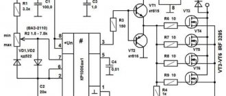
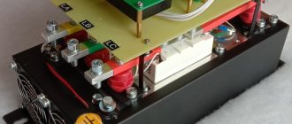
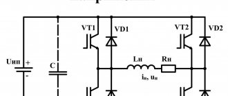
The most acceptable option would be a regulator based on a triac or thyristor. Not only does such a regulator not reduce power when the voltage decreases, it also allows for smoother starting and speed control. In addition, such a scheme can be made with your own hands. Below is a picture of the speed control with power maintenance. The circuit is assembled on the basis of a BTA 41,800 V triac.
All ratings of electrical elements are indicated in the diagram. This is the circuit after assembly, it works quite stably and provides smooth adjustment of the brushed motor. When the output voltage decreases, the power does not decrease, which is a significant plus.
If desired, you can assemble the speed controller of a 220 V brushed motor with your own hands. This circuit is assembled on the basis of a VTA26-600 triac, which must first be installed on a radiator, since this element gets quite hot under load.
The diagram looks like this.
It can successfully cope with the adjustment of power tools such as a drill, grinder, circular saw, and jigsaw. If desired, you can use the circuit as a power regulator for heating elements, heaters, and as a dimmer. The disadvantages include the impossibility of adjusting the power of devices powered by direct current.
https://youtube.com/watch?v=vVeR4jVfTIg
General information
AC electric motors have become widespread in many areas of human activity, namely asynchronous-type models. The main purpose of the engine as an electric machine is the transformation of electrical energy into mechanical energy . Asynchronous in translation means non-simultaneous, since the rotor speed differs from the frequency of the alternating voltage (U) in the stator. There are two types of asynchronous motors based on the type of power supply:
Single-phase ones are used for household needs, and three-phase ones are used in production. Three-phase asynchronous motors (hereinafter referred to as TAM) use two types of rotors:
- closed;
- phase
Closed-circuit motors make up about 95% of all motors used and have significant power (from 250 W and above). The phase type is structurally different from AD , but is used quite rarely compared to the first. The rotor is a cylindrical steel figure that is placed inside the stator, with a core pressed onto its surface.
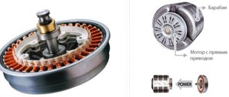
Squirrel cage and wound rotors
Highly conductive copper (for high-power machines) or aluminum rods (for lower-power machines) soldered or poured into the surface of the core and short-circuited at the ends with two rings play the role of electromagnets with poles facing the stator. The winding rods do not have any insulation, since the voltage in such a winding is zero.
More commonly used for mid-power motor cores, aluminum has low density and high electrical conductivity.
Read also: Submersible water heater for a summer residence
To reduce the higher harmonics of the electromotive force (EMF) and eliminate the pulsation of the magnetic field, the rotor rods have a specifically calculated angle of inclination relative to the axis of rotation. If a low-power electric motor is used, the grooves are closed structures that separate the rotor from the gap in order to increase the inductive component of the resistance.
The rotor in the form of a phase design or type is characterized by a winding, its ends are connected in a star type and attached to slip rings (on the shaft), along which graphite brushes slide. To eliminate eddy currents, the surface of the windings is covered with an oxide film. In addition, a resistor is added to the rotor winding circuit, which allows you to change the active resistance (R) of the rotor circuit to reduce the values of inrush currents (Ip). Starting currents negatively affect the electrical and mechanical parts of the electric motor. Variable resistors used to regulate Ip:
- Metal or stepped with manual switching.
- Liquid (due to immersion to the depth of the electrodes).
Graphite brushes are subject to wear, and some models are equipped with a squirrel-cage design that lifts the brushes and closes the rings after the motor starts. IMs with a wound rotor are more flexible in terms of regulation of Ip.
Design features
An asynchronous motor does not have pronounced poles, unlike a DC electric motor. The number of poles is determined by the number of coils in the windings of the stationary part (stator) and the method of connection. In an asynchronous machine with 4 coils, a magnetic flux passes through. The stator is made of special steel sheets (electrical steel), which reduce eddy currents to zero, at which significant heating of the windings occurs. It leads to a massive interturn short circuit.
The iron ore or rotor core is pressed directly onto the shaft. There is a minimum air gap between the rotor and stator. The rotor winding is made in the form of a “squirrel cage” and is made of copper or aluminum rods.
In electric motors with a power of up to 100 kW, aluminum, which has a low density, is used to fill the grooves of the rotor core. But despite this device, engines of this type get hot. To solve this problem, fans are used for forced cooling , which are mounted on the shaft. These engines are simple and reliable. However, motors consume a large current when starting, 7 times the rated current. Because of this, they have a low starting torque, since most of the electrical energy goes to heating the windings.
Electric motors, which have an increased starting torque, differ from ordinary asynchronous motors in the design of the rotor. The rotor is made in the form of a double “squirrel cage”. These models are similar to the phase types of rotor manufacturing. It consists of an inner and outer “squirrel cage”, and the outer one is the starting one and has a large active and small reactive R. The outer one has a slight active and high reactive R. As the rotation speed increases, I switches to the inner cage and operates in the form of a squirrel-cage rotor.
Principle of operation
When I flows through the stator winding, a magnetic flux (F) is created in each of them. These F are shifted by 120 degrees relative to each other. The resulting F is rotating, creating an electromotive force (EMF) in aluminum or copper conductors. As a result of this, a starting magnetic moment of the electric motor is created, and the rotor begins to rotate. This process is also called slip (S) in some sources, showing the frequency difference n1 of the electromagnetic field of the starter, which becomes greater than the frequency obtained when rotor n2 rotates. It is calculated as a percentage and has the form: S = ((n1-n2)/n1) * 100%.
The value of S at the initial start of the electric motor is approximately 1, but as the values increase, n2 becomes smaller. At this moment, I in the rotor decreases, therefore, the EMF becomes less than its nominal value. At idle, S is minimal, but as the moment of static interaction between the rotor and stator increases, this value reaches a critical value. If the inequality is satisfied: S > Scr, then the motor operates normally, but if the value of Scr is exceeded, it may “capsize”. Rollover causes unstable operation but disappears over time.
Design Features
The microcircuit is equipped with everything necessary for high-quality engine control in various speed modes, from braking to acceleration and rotation at maximum speed. Therefore, its use greatly simplifies the design, while simultaneously making the entire drive universal, since you can select any speed with a constant torque on the shaft and use it not only as a drive for a conveyor belt or drilling machine, but also for moving a table.
The characteristics of the microcircuit can be found on the official website. We will indicate the main features that will be required to construct the converter. These include: an integrated frequency-to-voltage conversion circuit, an acceleration generator, a soft starter, a Tacho signal processing unit, a current limiting module, etc. As you can see, the circuit is equipped with a number of protections that will ensure stable operation of the regulator in different modes.
The figure below shows a typical circuit diagram for connecting a microcircuit.
The scheme is simple, so it is quite reproducible with your own hands. There are some features that include limit values and speed control method:
- The maximum current in the motor windings should not exceed 10 A (subject to the configuration shown in the diagram). If you use a triac with a large forward current, the power can be higher. Please note that you will need to change the resistance in the feedback circuit downward, as well as the inductance of the shunt.
- The maximum rotation speed is 3200 rpm. This characteristic depends on the type of engine. The circuit can control motors up to 16 thousand rpm.
- Acceleration time to maximum speed reaches 1 second.
- Normal acceleration is achieved in 10 seconds from 800 to 1300 rpm.
- The engine uses an 8-pole tachogenerator with a maximum output voltage of 30 V at 6000 rpm. That is, it should produce 8 mV per 1 rpm. At 15,000 rpm it should show 12 V.
- To control the motor, a 15A triac with a maximum voltage of 600 V is used.
If you need to organize a motor reverse, then for this you will have to supplement the circuit with a starter that will switch the direction of the excitation winding. You will also need a zero speed control circuit to give permission for reverse. Not shown in the picture.
Speed setting methods
To prevent negative influence during start-up, you need to reduce the speed of the electric motor 220 V or 380 V. There are several ways to achieve this goal:
- Changing the R value of the rotor circuit.
- Change in U in the stator winding.
- Change of frequency U.
- Switching poles.
When changing the R value of the rotor part using additional resistors, the rotation speed decreases, but as a result, the power decreases. Consequently, there is a significant loss of electricity. This type of regulation should be used for a wound rotor.
By changing the U values on the stator coil, mechanical or electrical control of the rotor speed is possible. In this case, the U regulator is used. Using this method allows it to be used only with a fan load (for example, a 220V fan speed regulator). For all other cases, three-phase automatic transformers are used, which allow smooth changes in U values, or thyristor regulators.
Based on the formula for the dependence of the rotation speed on the supply frequency U, it is possible to regulate the number of rotor revolutions. The frequency of the rotating magnetic field of the stator is calculated by the formula: Nst = 60 * f / p (f is the frequency of the supply network current, p is the number of pole pairs). This method provides the ability to smoothly control the rotation speed of the rotor part. To obtain a high efficiency, you need to change the frequency and U. This method is optimal for engines with a squirrel-cage rotor, since power losses are minimal. There are two methods for changing the number of pole pairs:
- In the stator (in the slots) you need to place 2 windings with different numbers p.
- The winding consists of two parts connected in parallel or in series.
Read also: Automatic switching to backup power from the generator
The main disadvantage of this method is maintaining a stepwise change in the frequency of an electric motor with a squirrel-cage rotor.
Using Pulse Width Modulation
To control and adjust the speed of rotation of an asynchronous type electric motor, you can use a pulse regulator-voltage stabilizer (inverter). It will act as a power source. It is based on the use of a TL494 pulse PWM regulator. The supply voltage of the electric motor, coming out after the PWM controller, will change in accordance with the change in rotation speed. Using this method, a greater economic effect is achieved, the device is quite simple and at the same time increases the efficiency of regulation.
The figure above shows a diagram of using a PWM controller for a three-phase asynchronous motor connected through a capacitor to a single-phase network.
This method, despite its effectiveness, has two significant drawbacks:
- impossibility of reverse motor control without the use of additional switching devices;
- frequency converters used in the regulator are high cost and are produced by a limited number of manufacturers.
Types and selection criteria
To select a regulator, you need to be guided by certain characteristics for a particular case. Among all the criteria, you can choose the following:
- By type of control. For commutator-type motors, regulators with a vector or scalar control system are used.
- Power is the main parameter from which you need to build.
- By U band.
- By frequency range. You need to choose a model that meets the user's requirements for a particular case.
- Other characteristics, which include warranty, dimensions, equipment.
In addition, the regulator is selected more powerful than the electric motor itself according to the formula: Preg = 1.3 * Pmot (Preg, Pmot is the power of the regulator and the motor, respectively). It must be selected for different U ranges, since versatility plays an important role.
Thyristor device
This model, shown in Diagram 1, uses 2 thyristors connected back-to-back, although they can be replaced with one triac.
Scheme 1 - Thyristor speed control of a commutator motor without loss of power.
This circuit performs regulation by opening or closing thyristors (triacs) during a phase transition through the neutral. To correctly control a commutator motor, the following methods of modifying circuit 1 are used:
- Installation of LRC protective circuits consisting of capacitors, resistors and chokes.
- Adding capacitance at the input.
- The use of thyristors or triacs, the current of which exceeds the rated value of the motor current in the range of 3..8 times.
This type of regulator has advantages and disadvantages. The first include low cost, low weight and dimensions. The second ones include the following:
- application for low power motors;
- there is noise and jerking of the motor;
- when using a circuit based on triacs, a constant U hits the motor.
This type of regulator is installed in fans, air conditioners, washing machines and electric drills. Performs its functions perfectly, despite its shortcomings.
Transistor type
Another name for a transistor-type regulator is an autotransformer or PWM regulator (scheme 2). It changes the value of U according to the principle of pulse width modulation (PWM) using an output stage that uses IGBT transistors.
Scheme 2 - Transistor PWM speed controller.
Switching of transistors occurs at a high frequency and thanks to this it is possible to change the width of the pulses. Consequently, the value of U will also change. The longer the pulse and the shorter the pause, the higher the value of U and vice versa. The positive aspects of using this variety are as follows:
- Low weight of the device with small dimensions.
- Quite low cost.
- At low speeds there is no noise.
- Control via low U values (0..12 V).
The main disadvantage of the application is that the distance to the electric motor should be no more than 4 meters.
Frequency regulation
Regulating the speed of motors of various types due to frequency is widely used. Frequency conversion occupies a leading position in the market for sales of speed control devices and soft starting. Thanks to its versatility, it is possible to influence the power, performance and speed of any device with an electric motor. These devices are used for single-phase and three-phase motors. The following types of frequency converters are used:
- Specialized single-phase.
- Three-phase without capacitor.
To regulate the speed, a capacitor is used, connected to the windings of a single-phase motor (diagram 3). This frequency converter (FC) has a capacitive R, which depends on the frequency of the flowing alternating current. The output stage of such an inverter is made of IGBT transistors.
Scheme 3 - Frequency speed controller.
A specialized inverter has its advantages and disadvantages. The advantages are the following:
- Blood pressure control without human intervention.
- Stability.
- Additional features.
It is possible to control the operation of the electric motor under certain conditions, as well as protection against overloads and short-circuit currents. In addition, it is possible to expand the functionality by connecting digital sensors, monitoring operating parameters and using a PID controller. The disadvantages include limitations in frequency control and a fairly high cost.
For three-phase IM, frequency control devices are also used (Scheme 4). The regulator has three phases at the output for connecting an electric motor.
Scheme 4 - inverter for a three-phase motor.
This option also has its strengths and weaknesses. The first include the following: low cost, choice of power, wide range of frequency regulation, as well as all the advantages of single-phase frequency converters. Among all the negative aspects, the main ones can be identified: preliminary selection and heating during startup.
Changing the speed of an IM with a squirrel-cage rotor
There are several ways:
- Rotation control by changing the electromagnetic field of the stator: frequency regulation and changing the number of pole pairs.
- Changing the slip of the electric motor by decreasing or increasing the voltage (can be used for IMs with a wound rotor).
Frequency regulation
In this case, the adjustment is made using a frequency conversion device connected to the engine. For this purpose, powerful thyristor converters are used. The process of frequency regulation can be considered using the example of the EMF formula of a transformer:
This expression means that in order to maintain a constant magnetic flux, which means maintaining the overload capacity of the electric motor, the supply voltage level should be adjusted simultaneously with frequency conversion. If the expression calculated by the formula is saved:
then this means that the critical moment has not been changed. And the mechanical characteristics correspond to the figure below; if you do not understand what these characteristics mean, then in this case the adjustment occurs without loss of power and torque.
The advantages of this method are:
- smooth regulation;
- changing the rotor speed up and down;
- rigid mechanical characteristics;
- efficiency.
There is only one drawback - the need for a frequency converter, i.e. increase in the cost of the mechanism. By the way, on the modern market there are models with single-phase and three-phase input, the cost of which with a power of 2-3 kW is in the range of 100-150 dollars, which is not too expensive for full adjustment of the drive of machine tools in a private workshop.
Switching the number of pole pairs
This method is used for multi-speed motors with complex windings that allow you to change the number of pairs of its poles. The most widely used are two-speed, three-speed and four-speed IMs. The adjustment principle is easiest to consider on the basis of a two-speed IM. In such a machine, the winding of each phase consists of two half-windings. The rotation speed changes when connecting them in series or parallel.
In a four-speed electric motor, the winding is made in the form of two parts independent from each other. When the number of pole pairs of the first winding changes, the speed of the electric motor changes from 3000 to 1500 rpm. Using the second winding, rotation is adjusted at 1000 and 500 rpm.
When the number of pole pairs changes, the critical moment also changes. To keep it unchanged, it is necessary to simultaneously regulate the supply voltage while changing the number of pole pairs, for example, by switching the star-delta circuit and their variations.
Advantages of this method:
- rigid mechanical characteristics of the engine;
- high efficiency.
- step adjustment;
- large weight and overall dimensions;
- high cost of the electric motor.
DIY making
If there is no opportunity or desire to purchase a factory-type regulator, then you can assemble it yourself. Although regulators of the "tda1085" type have proven themselves very well. To do this, you need to familiarize yourself with the theory in detail and start practicing. Triac circuits are very popular, in particular the speed controller of a 220V asynchronous motor (diagram 5). It's not difficult to make. It is assembled using a VT138 triac, which is well suited for these purposes.
Scheme 5 - Simple speed controller on a triac.
This regulator can also be used to adjust the speed of a 12-volt DC motor, as it is quite simple and universal. The speed is regulated by changing the parameters P1, which determines the phase of the incoming signal, which opens the transition of the triac.
The operating principle is simple. When the engine starts, it slows down, the inductance changes downward and contributes to an increase in U in the “R2—>P1—>C2” circuit. When C2 is discharged, the triac opens for some time.
There is another scheme. It works a little differently: by providing a reverse type of energy flow, which is optimally beneficial. The circuit includes a fairly powerful thyristor.
Scheme 6 - Design of a thyristor regulator.
The circuit consists of a control signal generator, an amplifier, a thyristor and a circuit section that functions as a rotor rotation stabilizer.
The most universal circuit is a regulator based on a triac and dinistor (scheme 7). It is able to smoothly reduce the shaft rotation speed, reverse the motor (change the direction of rotation) and reduce the starting current.
Read also: How to check a triac on a board
The principle of operation of the circuit:
- C1 is charged until U breakdown of dinistor D1 through R2.
- When D1 breaks, it opens the junction of triac D2, which is responsible for controlling the load.
The load voltage is directly proportional to the frequency component when D2 opens, which depends on R2. The circuit is used in vacuum cleaners. It contains universal electronic control, as well as the ability to easily connect 380 V power. All parts should be placed on a printed circuit board made using laser-iron technology (LUT). You can find out more about this board manufacturing technology on the Internet.
Thus, when choosing an electric motor speed controller, you can buy a factory one or make it yourself. Making a homemade regulator is quite simple, since if you understand the principle of operation of the device, you can easily assemble it. In addition, you should follow safety rules when installing parts and when working with electricity.
Commutator motors can often be found in household electrical appliances and power tools: washing machine, grinder, drill, vacuum cleaner, etc. Which is not at all surprising, because commutator motors allow you to obtain both high speeds and high torque (including high starting torque ) - which is what you need for most power tools.
In this case, commutator motors can be powered by both direct current (in particular, rectified) and alternating current from a household network. To control the rotor speed of a commutator motor, speed controllers are used, which will be discussed in this article.
First, let's remember the design and principle of operation of a commutator motor. The commutator motor necessarily includes the following parts: rotor, stator and brush-collector switching unit. When power is applied to the stator and rotor, their magnetic fields begin to interact and the rotor eventually begins to rotate.
Power is supplied to the rotor through graphite brushes that fit tightly to the commutator (to the commutator lamellas). To change the direction of rotation of the rotor, it is necessary to change the phasing of the voltage on the stator or on the rotor.
The rotor and stator windings can be powered from different sources or can be connected in parallel or in series with each other. This is how commutator motors of parallel and series excitation differ. It is the series-excited commutator motors that can be found in most household electrical appliances, since such inclusion makes it possible to obtain a motor that is resistant to overloads.
Speaking about speed controllers, first of all we will focus on the simplest thyristor (triac) circuit (see below). This solution is used in vacuum cleaners, washing machines, grinders, and shows high reliability when operating in alternating current circuits (especially from a household network).
This circuit works quite simply: at each period of the mains voltage, the capacitor is charged through a resistor to the unlocking voltage of the dinistor connected to the control electrode of the main switch (triac), after which the triac opens and passes current to the load (to the commutator motor).
By adjusting the charging time of the capacitor in the triac opening control circuit, the average power supplied to the engine is regulated, and the speed is adjusted accordingly. This is the simplest regulator without current feedback.
The triac circuit is similar to a regular dimmer for adjusting the brightness of incandescent lamps; there is no feedback in it. To provide current feedback, for example to maintain acceptable power and avoid overloads, additional electronics are required. But if we consider the options from simple and straightforward circuits, then the triac circuit is followed by a rheostat circuit.
The rheostat circuit allows you to effectively regulate speed, but leads to the dissipation of a large amount of heat. This requires a radiator and effective heat removal, which means energy loss and low efficiency as a result.
Regulator circuits based on special thyristor control circuits or at least on an integrated timer are more effective. Switching of the load (commutator motor) on alternating current is carried out by a power transistor (or thyristor), which opens and closes one or more times during each period of the network sinusoid. This regulates the average power supplied to the engine.
The control circuit is powered by 12 volts DC from its own source or from a 220 volt network through a quenching circuit. Such circuits are suitable for controlling powerful motors.
The principle of regulation with DC microcircuits is, of course, PWM - pulse width modulation. A transistor, for example, opens with a strictly specified frequency of several kilohertz, but the duration of the open state is regulated. So, by rotating the handle of the variable resistor, the rotation speed of the rotor of the commutator motor is set. This method is convenient for maintaining low speeds of a commutator motor under load.
Better control is direct current regulation. When PWM operates at a frequency of about 15 kHz, adjusting the pulse width controls the voltage at approximately the same current. Let's say, by adjusting the constant voltage in the range from 10 to 30 volts, they get different speeds at a current of about 80 amperes, achieving the required average power.
Speed controller for commutator motor on TDA1085:
If you want to make a simple regulator for a commutator motor with your own hands without any special requests for feedback, then you can choose a thyristor circuit. All you need is a soldering iron, a capacitor, a dinistor, a thyristor, a pair of resistors and wires.
If you need a higher-quality regulator with the ability to maintain stable speeds under dynamic loads, take a closer look at regulators on microcircuits with feedback that can process the signal from the tachogenerator (speed sensor) of a commutator motor, as is implemented, for example, in washing machines.
Measurements
It is clear that the number of revolutions needs to be determined somehow. Tachometers are used for this. They show the rotation number at the moment. You can’t simply measure speed with a regular multimeter, except in a car.
As you can see, on electric machines you can change various parameters, adjusting them to the needs of production and household use.
DIY birthday decor
Close…
Pointed-toe cowboy bootsThe principle of operation of a homemade lock is as follows. In one half there is a permanent magnet. and in the other there is a metal plate. One of them is attached to the door. The second, with the metal plate removed, is equipped with a KEM-1 reed switch and attached to the door frame. If the door is in the closed position, the two parts of the lock are pressed, the magnet acts on the reed switch, closing its contacts. If the door opens, the magnet goes away and the reed switch contacts open.
The battery, the computer system unit, even the power supply for a laptop are all best friends. I’m already silent about such good hot water bottles as my husband and I.
Take the filler and stuff the doll. When the stuffing is completely evenly distributed, sew the product up. The handles must be sewn to the body almost near the neck.
From one pallet, sanded, impregnated and varnished, you get a garden table like a coffee table, on the left in Fig. If you have a pair in stock, you can make a wall-mounted work desk-rack out of them in literally half an hour, in the center and on the right. You can also weave chains for it yourself from soft wire, covered with a PVC tube or, better, heat-shrinkable. To fully raise the tabletop, small tools are placed on the shelf of a wall pallet.
Well, if you fill a glass bowl, vase, candy dish, punch vessel or ordinary glasses with water, scattering sea pebbles on the bottom, and let the candle-tablets float freely, you will get magical lighting for a romantic New Year. For a more interesting and unexpected effect, you can experiment with the color of the water. How are studs installed on rubber?
Handmade toys for children are beautiful, cheap and enjoyable. Every child needs original and educational toys, but it is not always possible to purchase them. Today we will show you 5 examples of fun toys that you can make yourself. They can be made from cardboard, paper or wood. In general, be inspired and make your children happy more often.
For the base of such a structure, you can use thick plywood, and for its upper part - polycarbonate. Finding solar panels online today is also not a problem.
Attention! When joining panels, do not use too much force, as you may damage the joint. This is exactly how many knives a housewife should have in her kitchen so that the cooking process is always simple and enjoyable.
This is exactly how many knives a housewife should have in her kitchen so that the cooking process is always simple and enjoyable.
To make a feeder with your own hands we will need:
Timber calculation. The boards, called staves, have biconvex sides to give the cooperage product a convexity. To make them like this, you need to take the lower part of a tree trunk and split it, similar to chopping wood. If you cut it carefully, the natural integrity of the fibers will be disrupted, which is bad for such a product. You shouldn’t start figure sawing right away - the logs need to be dried for 2 months. Moreover, dry it not under the scorching sun, but in a dark, cool room.
How to weave bracelets from laces
The fact that most New Year's costumes for preschool children are easily sewn on the basis of overalls can significantly narrow and facilitate creative search. If you learn how to sew a jumpsuit - the basis for a New Year's costume and come up with (draw from) and make decorative elements for it with your own hands, then you can make amazing and quite interesting models of New Year's outfits for children. The main thing is to think through everything in advance to the smallest detail, arm yourself with knowledge on the topic - so that the result of the work will pleasantly surprise and delight everyone.
Wardrobe design
Images
DIY birthday gift for mom photo instructions
Similar news
.
With the ever-increasing growth of automation in the domestic sector, there is a need for modern systems and devices for controlling electric motors.
Control and frequency conversion in small-power single-phase asynchronous motors, launched using capacitors, allows you to save energy and activates the energy saving mode at a new, progressive level.
Variable drive configuration
The frequency converter is formed from three components:
- A controlled or uncontrolled rectifier responsible for generating the DC (direct current) voltage supplied from the power supply.
- A filter (in the form of a capacitor) that provides additional voltage smoothing.
- An inverter that simulates the voltage of the desired frequency.
Self-connection of the converter
Before you start connecting the device, you should use a de-energizing circuit breaker; it will ensure that the entire system is turned off in the event of a short circuit to any of the phases.
There are two schemes for connecting an electric motor to a frequency converter:
- "Triangle".
The diagram is relevant if you need to control a single-phase drive. The power level of the converter in the circuit is up to three kilowatts, and no power is lost.
- "Star".
A method suitable for connecting the terminals of three-phase frequency drives powered by industrial three-phase networks.
The figure shows the connection diagram for the 8400 Vector.
To limit the starting current and reduce the starting torque when starting an electric motor with a power exceeding 5 kW, star-delta switching is used.
When voltage is applied to the stator, the device is connected as a star. As soon as the motor speed begins to correspond to the nominal value, power is supplied according to the “triangle” circuit. But this technique is used only when technical capabilities allow connecting in two circuits.
In a combined star and delta circuit, sharp current surges are observed. When switching to the second type of connection, the rotational speed readings decrease significantly. To restore the previous operating mode and speed, the current should be increased.
Frequency generators are most actively used in the design of an electric motor with a power level of 0.4 - 7.5 kW.
DIY frequency converter assembly
Simultaneously with the industrial production of frequency converters, assembling such a device with your own hands remains relevant. This is especially facilitated by the relative simplicity of the process. As a result of the inverter's operation, one phase is converted into three.
The use of electric motors equipped with a similar device in domestic conditions does not cause any additional difficulties. Therefore, you can safely get down to business.
The figure shows a block diagram of frequency converters with a DC link.
The frequency converter circuits used during assembly consist of a rectifier unit, filter elements (responsible for cutting off the alternating current component and constructed from IGBT transistors). In terms of cost, purchasing individual components of the converter and doing the assembly yourself is cheaper than purchasing a finished device.
Self-assembled frequency converters can be used in electric motors with a power of 0.1 - 0.75 kW.
At the same time, modern factory frequency generators have expanded functionality, improved algorithms and improved control over the safety of the work process due to the fact that microcontrollers are used in their production.
Areas of application of converters:
- Mechanical engineering;
- Textile industry;
- Fuel and energy complexes;
- Borehole and sewage pumps;
- Automation of process control.
The cost of electric motors is directly dependent on whether it is equipped with converters.
Frequency classification
There are several types of inverters based on the size and type of power supply:
- single-phase;
- three-phase;
- high voltage units.
Semiconductor frequency converters convert the current or voltage of an industrial network. The output parameters of the required signal are freely regulated by the control elements.
Voltage regulation
Speed control in this way is associated with a change in the so-called engine slip - the difference between the rotation speed of the magnetic field created by the stationary engine stator and its moving rotor:
n1— magnetic field rotation speed
n2 — rotor rotation speed
In this case, sliding energy is necessarily released - which causes the motor windings to heat up more.
This method has a small control range, approximately 2:1, and can also only be carried out downwards - that is, by reducing the supply voltage.