Angle grinder Fiolent MSHU2-9-125E with speed control. Photo VseInstruments.ru
There is always a use for an angle grinder at home, in the country, in the garage or as a professional tool in production workshops. The use of various working tools increases the functionality of the work performed . Compliance with operating rules increases the service life of the power tool. However, as with any mechanism, sooner or later malfunctions occur . Easy assembly/disassembly, availability of diagnostic and repair tools allow you to fix breakdowns yourself.
Bulgarian and its operation
An angle grinder is called an angle grinder. The name of the instrument is due to the fact that it was produced in Plovdiv. It is intended for performing work on grinding or trimming hard material:
Does a good job of sharpening tools.
A grinder is a very necessary tool these days, so almost everyone has one.
There are grinding machines of different power: from 500 W to 2500, depending on the thickness of the wheel - from 115 mm to 230 mm. The most popular ones in use are angle grinders with a power of 1.2 W, and the most used disc is 125 mm thick.
Every year the choice for this construction power tool becomes wider, but the operating rules remain almost unchanged. And even if you always adhere to them, sooner or later malfunctions arise in the mechanism, which you can try to fix yourself by collecting everything you need to repair the angle grinder.
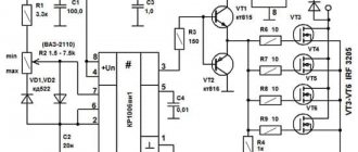
Typical speed controller circuit
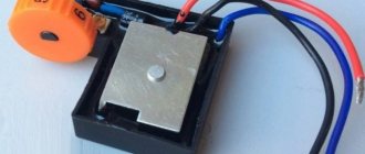
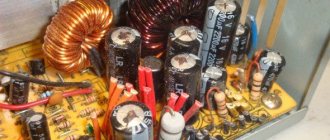
This is what the assembled speed controller board looks like
The engine speed controller is not just a variable resistor that lowers the voltage. Electronic control of the current strength is necessary, otherwise, as the speed drops, the power and, accordingly, the torque will decrease proportionally. In the end, a critically low voltage value will occur when, even with the slightest resistance of the disk, the electric motor simply cannot turn the shaft. Therefore, even the simplest regulator must be calculated and implemented in the form of a well-developed circuit.
And more advanced (and therefore expensive) models are equipped with regulators based on an integrated circuit.
Integrated controller circuit. (the most advanced option)
If we consider the electrical circuit of the angle grinder in principle, it consists of a speed controller and a soft start module. Power tools equipped with advanced electronic systems are significantly more expensive than their simpler counterparts. Therefore, not every home craftsman is able to purchase such a model. And without these electronic units, all that remains is the electric motor winding and the power button.
The reliability of modern electronic components of angle grinders exceeds the service life of motor windings, so you should not be afraid of purchasing a power tool equipped with such devices. The only limiting factor can be the price of the product. Moreover, users of inexpensive models without a regulator sooner or later come to install it themselves. The block can be purchased ready-made or made independently.
What is a speed controller and what is it for?
This device is designed to control the power of an electric motor. With its help you can regulate the speed of rotation of the shaft. The numbers on the adjustment wheel indicate a change in the rotation speed of the disk.
The regulator is not installed on all angle grinders.
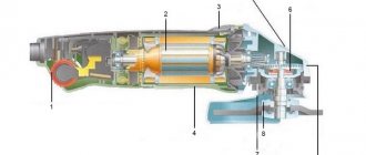
Angle grinder device
Any grinder consists of the following parts:
- rotor - part of the electric motor that rotates during operation and is controlled in speed, also called an armature;
- collector - the place on the rotor where the control winding wires are located;
- brushes - parts that serve as current conductors from the cable to the commutator winding;
- gearbox - a mechanism that acts as a drive from a rotating rotor to a spinning disk, consists of a spindle, a bearing, and two gears (a large gear and a shaft gear);
- stator – part of the electric motor in which the rotor operates;
- grinder cooling impeller;
- start button;
- electrically driven network cable;
- protection casing;
- grinder body;
- additional handle.
All these details can be divided into two parts:
For what purpose does an angle grinder have low speeds?
The integrated option for adjusting the speed of the wheel makes it possible to carefully process materials such as wood or plastic.
At lower speeds, comfort and safety increase. This option is most practical in radio and electrical installations, service stations and restoration studios. In addition, among professionals who use power tools, there is a belief that the more trivial a device is, the more reliable it is. And it is advisable to take the additional service “filling” beyond the boundaries of the grinder. With this approach, equipment maintenance is greatly simplified. In this regard, some companies deliberately produce remote individual electric regulators that connect to the network cable of an angle grinder.
This is interesting: How to work with a grinder correctly - cutting, sawing, holding, placing the disc
How to disassemble an angle grinder
How to disassemble an angle grinder? It's not such a complicated process. This does not require special knowledge, but everything must be done carefully and with caution. Every owner needs to know how to disassemble any working tool, because periodically it needs internal cleaning from dirt and dust, and its service life depends on this.
Nowadays on the market you can choose different types of grinders, which differ in operating parameters, size, and quality. Manufacturers are also different. Whatever model of grinding machine you buy, they all have the same model for assembling parts.
Disassembling the angle grinder will require few tools; you just need a regular screwdriver or a reversible one with a ratchet mechanism.
Having prepared the screwdriver, you can start disassembling:
- We unscrew the screws from the body and remove one side of the product.
- Remove the nut that holds the disk in place and unscrew the bolts securing the protective casing.
- Remove the brushes.
- Disconnect the wires from the engine.
- We unscrew the bolts that secure the gearbox inside and very carefully remove it; the rotor is also removed with it.
- We unscrew the bolts that hold the stator and remove it.
- We assemble the angle grinder back, put everything in place one by one in reverse order and screw it on.
When disassembling an angle grinder, it is important to remember the order in which parts are removed in order to assemble it correctly.
How to assemble a regulator with your own hands?
A simplified and quite reliable frequency converter for angle grinders is built with your own hands from available electrical parts. Below is a diagram that shows all the required components for mounting the device we are interested in on a printed circuit board.
- symmetrical triode thyristor (or triac, triac) DIAC (DB3);
- resistor (resistance) R1 (its parameters should be 4.7 kOhm);
- additional triac VT136/138 (TRIAC);
- capacitor C1 (400 V, 0.1 µF);
- additional resistance VR1 at 500 kOhm.
A similar scheme operates according to the following method.
- The charging time of the capacitor is modified by an auxiliary resistor (called a tuning resistor). When voltage is applied to the circuit, the triacs are in the closed position, and a zero voltage value is observed at the output.
- During the charging process of the capacitor, an increase in the voltage across it is observed, which leads to the opening of the DB3 triac. As a result of this, voltage falls on VT136/138. This thyristor element also opens, and electric current flows through it.
- After this, the symmetrical components close again and remain in a similar status until the capacitor is completely recharged in the opposite direction.
- Ultimately, at the output we obtain a deterministic signal of finite energy that is complex in configuration. Its exact range is determined by the period of execution of the functions of the circuit capacitor - auxiliary resistance - resistance R1.
Triacs are usually located on a printed circuit board. It is easy to create from PCB (multilayer pressed plastic consisting of heat-insulating fiber and foil is used). Individual craftsmen cut out the board using a cutter. It is practiced to place circuit elements using the hinged mounting method. Triacs are mounted only on an aluminum or copper heat exchanger. It acts as a good heat sink.
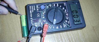
The assembled device is tested using an ordinary 40-60 W incandescent lamp. Connect it to the circuit and begin adjusting the glow power. If the brightness changes, then you did everything correctly. Now you can begin installing the regulator into the shell of the angle grinder. This is not very easy to do, since it is necessary to ensure that the auxiliary device does not interfere with you when using the angle grinder.
You will need to calculate the installation location of the homemade control device yourself, in accordance with the design features of the angle grinder. Installation of the circuit is done:
- in an additional box mounted on the unit body;
- into the holder handle;
- into a small empty niche (it is intended for cooling and circulating air masses) in the rear area of the angle grinder.
The circuit itself is connected to the device by integrating it into the electrical power channel of the angle grinder. You probably won’t have any difficulties with this.
Types of breakdowns in grinders
Typical minor damage
In the event of a malfunction, it is first necessary to eliminate elementary breakdowns:
- The grinder does not turn on. The angle grinder suddenly became faulty - it stopped turning on. In this case, you need to check the serviceability of the socket, then the plug and the power cord; perhaps the drive simply does not work due to the fact that no current flows into the product.
- The cable and plug are intact, but the drive does not work. You need to check the start button. It is easier to repair an angle grinder switch by purchasing a new button and replacing it. Since it is rarely repairable - mainly, the plastic switch rod inside breaks. If you want to experiment, you can disassemble it, numbering the contacts, and put everything back in its place so that after assembly there is no short circuit.
- The above parts are unharmed, but the angle grinder does not want to work - which means it’s time to check the brushes. Perhaps it's time to change them in the grinder. Brushes constantly heat up from work, so they wear out quickly and need to be replaced more often than other parts, and in pairs.
Major faults
Having ruled out all minor damage, you need to figure out why the tool does not want to turn on and how to repair it. Most likely, the malfunctions are serious and require additional knowledge. This happens if:
- the body is deformed;
- one of the bearings is jammed;
- the armature or stator does not work;
- the gear teeth of the gearbox are broken or worn out;
- the collector has failed;
- The control electronics sensor shows no signs of life.
If it is determined that the malfunction has occurred in the mechanical part of the angle grinder, then you need to pay attention to the condition of the large gear located on the shaft and the bushings. If the teeth are partially worn out or the shafts become wobbly, they must be replaced immediately.
The most common breakdowns
Grinder malfunctions happen quite often. Everyone who works with this tool knows about this. What goes wrong most often?
The spindle lock button is broken.
Just one awkward press on the spindle lock button while the disk is rotating leads to its breakdown. Sometimes it can be broken if it is used to remove a jammed disk. To prevent this from happening, you need to use an open-end wrench inserted into special holes near the place where the disk is attached.
Features and service life
They can operate on direct and alternating current.
To power them, in most cases, a conventional electrical network of 230 V 50 Hz is used. Previously, a 380 V network was used for professional tools. Now, with the increase in consumer power in single-phase networks (offices and residential sector), professional power tools for 220 V have also appeared.
Commutator motors have high torque and starting torque, are compact, and can be easily manufactured for higher voltages. Torque is key here. With the low weight of the machine, it is just suitable for hand-held power tools. But such electric motors have disadvantages and weak points. One of these weak points is the brush assembly.
Brushes made of pressed graphite with fillers rub against the copper plates of the commutator and are subject to mechanical wear and electrical erosion. This leads to increased sparking and increases the fire and explosion hazard of the power tool. Ingress of mineral dust will accelerate wear. Although the fans provided in the design blow air outside, dust and cement can easily get inside. During downtime, if the tool is placed poorly, dust can easily get inside. In practice this is a constant occurrence.
Extruded graphite motor brushes
Another disadvantage of power tools is frequent gearbox breakdowns. This happens precisely because of the high starting torque. Advantage turns into disadvantage. If the gearbox breaks down, you have to change the tool; they usually cannot be repaired. Unfortunately, the industry, in an effort to reduce production costs, does so at the expense of quality. If you want to use a good power tool, pay a lot of money.
Characteristic symptoms of malfunctions
Before it completely breaks down, the angle grinder gives signals about the beginning of problems.
Pay attention to the work of your assistant: you should be wary if:
- the brushes began to spark excessively;
- The grinder gets hot during operation;
- the motor hums inside the housing when the tool is turned on;
- body vibration has become significantly greater during work;
- the grinder gearbox is cracking inside;
- the sound of bearings squeaking when spinning up or periodic wedging is heard when the rotor shaft rotates;
- The angle grinder is smoking, or there is an uncharacteristic smell of burning coming from it.
In order not to buy a new grinder, you need to be careful about the operation of the tool. In case of any deviations from the usual operation, begin troubleshooting, determine the cause and repair the power tool.
Checking the health of the stator
The stator is the stationary part of the electric motor that creates an electromagnetic field in which the rotor rotates. The cause of failure is often either a short circuit or a break in the turns of the stator winding (coil).
- water ingress;
- overheating caused by overloading the angle grinder;
- power surge;
- sharply pulling the tool plug out of the socket.
Signs indicating stator failure:
- appearance of smoke;
- smell of burnt insulation;
- overheating of the grinder body;
- stopping the rotation of the shaft or slowing it down;
- sudden spontaneous increase in speed.
Prevention of breakage of an angle grinder
The service life of a grinding machine directly depends on the owner’s care for it. Each tool needs good care, then it will work properly for a long time.
Any angle grinder will get warm during operation, but in order to postpone angle grinder repair for a long time, you must adhere to some rules in work:
- Do not overload the tool to avoid overheating and smoke.
- Do not forcefully press on it while working.
- Clean and lubricate the necessary parts inside the housing in a timely manner.
- If abnormal operation is noticeable, stop operation and inspect for problems.
- Replace wearing parts in a timely manner.
- If the grinder smokes, immediately stop working and do not turn it on again.
- Do not use the tool when processing wood-type materials.
- Hold the grinder firmly during operation so as not to drop or damage it.
By adhering to the listed simple recommendations and rules when working with a tool called an angle grinder, you can extend its service life longer than the warranty period.
Why adjust the rotation speed of the grinder disc at all?
- When cutting metal of different thicknesses, the quality of work greatly depends on the speed of rotation of the disk. If you are cutting hard and thick material, you must maintain maximum rotation speed. When processing thin sheet metal or soft metal (for example, aluminum), high speeds will lead to melting of the edge or rapid blurring of the working surface of the disk;
- Cutting and sawing stone and tile at high speed can be dangerous. In addition, the disk, which rotates at high speeds, knocks small pieces out of the material, making the cutting surface chipped. Moreover, different speeds are selected for different types of stone. Some minerals are processed at high speeds;
- Grinding and polishing work is in principle impossible without adjusting the rotation speed. By setting the speed incorrectly, you can damage the surface, especially if it is a paint coating on a car or a material with a low melting point;
- The use of discs of different diameters automatically implies the presence of a regulator. Changing a disk Ø115 mm to Ø230 mm, the rotation speed must be reduced by almost half. And holding a grinder with a 230 mm disc rotating at a speed of 10,000 rpm is almost impossible to hold in your hands;
- Polishing of stone and concrete surfaces, depending on the type of crowns used, is carried out at different speeds. Moreover, when the rotation speed decreases, the torque should not decrease;
- When using diamond discs, it is necessary to reduce the number of revolutions, since their surface quickly fails due to overheating. Of course, if your grinder works only as a cutter for pipes, angles and profiles, you won’t need a speed controller. And with the universal and versatile use of angle grinders, it is vital.
To come in
Already registered? Sign in here.
There are currently 0 users on the page
There are no users viewing this page.
The grinder, being the most popular tool in the house, is subjected to considerable loads and intensive use. Because of this, after some time it happens that when starting the engine, jerks, a burning smell and other malfunctions appear, suggesting that the angle grinder (angle grinder) has broken down. But you shouldn’t immediately take the device for repairs or buy a new one. Most malfunctions of this device can be resolved independently.
Features of checking the armature of an angle grinder with a tester
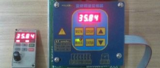
The diagnostic procedure will help to accurately determine the faulty part of the electric motor. A device that is available in the tool arsenal of many amateur electricians will allow you to check the armature of an angle grinder with a tester. Using the tester, you can check not only the armatures of angle grinders, but also the stator windings of other electric motors. In the video below you can see one of these homemade measuring devices in action.
When the tester is connected to the network, the indicator lights up. A red light without applying a technical device to the armature means the device is ready to perform the test. The working active surface of the measuring device has two points of contact with the test surface. One of them is a generator coil, the second is a communication curl coil. When checking the armature of an angle grinder with a tester, it is necessary to place this surface next to the groove being examined. Make sure that the sensors do not extend beyond the armature plates on both sides at the same time.
If the electrical part is in good condition or rewound, then when it is checked by a tester, the indicator opposite each of the grooves will light green. If there is a malfunction in the armature of the angle grinder, in particular, an interturn short circuit, a red light will appear on the device indicator at its location. Be careful when performing the diagnostic procedure to ensure correct contact of the surfaces when checking the angle grinder armature with a tester. Mechanical damage, which can be noticed visually without testing with a multimeter, should not be excluded as the reason for the failure of an angle grinder. They can be both significant and small. You may notice damage upon inspection after disassembling the angle grinder. It is necessary to diagnose such faults before checking the armature for an interturn short circuit.
If you do not have experience in disassembling power tools or preparing to work with measuring instruments for testing an armature with a multimeter and are not confident in your own abilities, you should not interfere with the design of the angle grinder. Do not experiment to avoid damaging the angle grinder. In this case, to find the cause of the breakdown of the power tool and check the armature of the angle grinder with a tester, it is better to contact a service center or qualified mechanics who specialize in equipment repair.
Design and electrical circuit of the grinder
Over the many years of existence of such a tool as an angle grinder, its appearance, as well as its internal structure, have remained virtually unchanged. To repair an angle grinder with your own hands, you need to know the structure of its mechanical part, as well as its electrical part.
If you look at the figure below, you can see what parts the angle grinder consists of.
- Wheel for adjusting the spindle speed of the unit.
- An electric motor consisting of a rotor and a stator.
- Start button. Sometimes a soft start system is connected to it.
- Housing made of impact-resistant plastic.
- Button for fixing the spindle (used when changing tools).
- Safety coupling. Protects the engine from overload when the tool jams.
- Protective cover. Covers the tool and protects the user from flying particles of the material being processed, and also prevents injury to a person when the tool, for example, an abrasive disc, is destroyed.
- Nut that clamps the tool. It is unscrewed using a special key that comes with the power tool. There are also quick-release nuts that can be unscrewed without a key.
- The gearbox housing and the gearbox itself. It consists of a block of gears that transmit rotational movements from the rotor to the spindle with the tool.
How to make a regulator from a dimmer?
A very effective and easy solution to this issue would be to create an external frequency converter. A dimmer can be used as a converter - a device for regulating the light level. When creating, you will need an electrical outlet and plug. It must be said that the implementation of such a device can be performed using different methods. Two are especially simple: with and without the use of a machine gun.
- Screw 2 wires to the ends of the electrical outlet so that one is longer. After this, connect the long end to one of the contacts on the plug. Fix the end of the 2nd wire to the dimmer contacts, and connect its other output to the 2nd contact of the plug.
- When using the 2nd option, it is necessary to make a number of modifications to the circuit, and specifically to place a machine on the cord between the plug and the dimmer. Basically, dimmers have ordinary switches, but we need an automatic one, which, if something goes wrong, will turn off our device from the mains.
So, the frequency converter of the angle grinder is ready, and for practicality it can be placed in a specialized housing or fixed on a wood panel. You just have to take into account that such a device is homemade, and when working with the electrical network, you need to be careful.
To learn how to make controller for an angle grinder with your own hands, see the video below.
The main malfunctions of an angle grinder and their causes
According to statistics, most cases of angle grinder failure are associated with the electrical part of the device. Some damage may be minor, which allows you to repair the angle grinder yourself. But, for example, if the motor windings burn out, only a specialist can repair an angle grinder.
Grinder won't turn on
The reasons that the angle grinder does not turn on may be the following:
- the electrical plug is faulty;
- the electrical cable is faulty;
- the start button is broken;
- the contact between the power cable and the button is broken;
- break in the contact wire of the electric brush;
- severe wear of electric brushes;
- failure of the rotor or stator windings.
The angle grinder does not develop speed
The reasons why the angle grinder does not gain momentum can be different.
- Damage to the speed control unit. To check this version, you need to connect the device’s motor directly, bypassing the regulator, and check the operation of the device.
- Failure of the electrical cable due to constant kinks or mechanical damage. Because of this, the damaged wire begins to heat up under load, and engine speed drops.
- Collector contamination with dust. Contaminants must be removed with alcohol.
- Problems with brushes. They may be worn out or have a short contact wire as shown in the following photo.
Although the brush is half worn out, it is still fully functional. In this case, a short contact wire prevents the spring from pressing the electrode to the collector. This situation may also be the reason why the angle grinder stopped working normally.
The electric motor is heating up
The reasons why the angle grinder is heating up may be the following.
- Incorrect operating mode of the device. As a result of overloads, the electric motor can become very hot, which often leads to burnout of the windings.
- Destruction of bearings located on the armature. As a result, the rotor clings to the stator, engine operation becomes difficult, and the windings overheat. The problem is solved by replacing the bearings.
- Clogged ventilation ducts through which air flows to cool the engine. The ventilation openings must be cleared of dust.
- Damage to the impeller used to cool the engine. It is installed on the rotor, on the side opposite to the collector. If the impeller is broken, it must be replaced with a new one.
- Interturn short circuits of stator and rotor windings. It will be necessary to rewind the reels or replace these parts with new ones.
Bulgarian sparkles
If you notice strong sparking when you turn on the angle grinder in the place where the collector is located, then the reasons for this trouble may be the following.
- Damage to the armature winding: break of one or more sections of the winding, interturn short circuit. With such breakdowns, increased noise appears, engine speed drops and brushes burn.
- The contact between the collector plates and the winding is broken.
- Weak brush pressure. During long-term operation of the angle grinder, the springs overheat and can “anneal”, thereby losing their elasticity.
- Engine rotor imbalance.
- Damage to the cylindrical surface of the collector. This sometimes happens after rewinding, if the armature is not turned on a lathe, but is immediately installed in the machine. In this case, you can also observe that the brushes spark excessively.
- The insulation between the collector lamellas is broken. There may also be clogging of the track grooves with graphite or a breakdown between the lamellas.
- Bearing wear, which causes the rotor to run out, also causes the brushes to spark heavily.
- Violation of the geometry of the armature shaft. This usually happens when the electric motor is disassembled carelessly and the shaft bends.
- Wrong brand of graphite brushes installed. Brushes are selected based on the expected speed and voltage.
- Raising one or more lamellas causes the brushes to quickly burn out. This happens due to engine overheating during prolonged operation. As a result, the glass melt, which serves as the basis of the collector, softens and the lamellas begin to rise. Due to the fact that the slats are raised, the brushes wear out very quickly.
Why do you need a soft start?
The presence of such a launch is a very important point. When starting a powerful power tool connected to the network, a surge of inrush current occurs, which is many times higher than the rated current of the motor, and the voltage in the network sags. Although this surge is short-lived, it causes increased wear on the brushes, the motor commutator and all the tool elements through which it flows. This can cause failure of the tool itself, especially Chinese ones, with unreliable windings that can burn out during switching on at the most inopportune moment. There is also a large mechanical jerk during startup, which leads to rapid wear of the gearbox. Such a start extends the life of the power tool and increases the level of comfort during operation.
Sources:
https://toolparts.com.ua/novosti/proverka-iakoria-testerom-rekomendatsii-spetsialistov https://kalina-2.ru/remont-vaz/shema-reguljatora-oborotov-bolgarki-bosh
How to disassemble an angle grinder for diagnostics
In order to diagnose the electrical part of the angle grinder, as well as eliminate mechanical breakdowns of the device, you will need to disassemble it. Disassembly is carried out according to the following algorithm.
- Using a wrench, remove the disk or other attachment from the spindle of the unit.
- Unscrew the handle.
- Remove the protective cover.
- Open the special windows located on the sides of the angle grinder casing and remove the electric brushes, having first disconnected the terminals.
- Unscrew the gear housing from the angle grinder motor housing.
- Pull the gear housing lightly and remove it from the housing. In this case, the gear unit will be removed along with the rotor.
- After removing the armature, the motor stator will remain in the casing, which can also be easily removed for diagnostics after unscrewing the fasteners.
- To disassemble the gearbox, unscrew the screws holding the cover. After removing the cover, you will see the gears of the gearbox.
- To remove the anchor from the angle grinder, you will need to unscrew the nut located inside the gearbox.
- In order to remove the bearing from the armature, it is recommended to use a special puller. Otherwise, the shaft may be damaged.
How to assemble an adjustment circuit?
The traditional speed control circuit is quite simple: phase-pulse triggering of a triac, there are only a few parts in it. However, it does not behave very stably, so a professional tool uses this principle in a complicated version, with feedback and overcurrent protection (U2008B and U2010B microcircuits).
Now more advanced options are appearing, using PWM controllers. Their circuits are a little more complicated, but the main difficulties arise during setup and assembly. Instruments (oscilloscope) and the ability to work with expensive parts that are afraid of static charges may be required. In general, this is not for ordinary consumers.
Therefore, it is better to take an average solution: a version with a triac and a U2008 microcircuit; this circuit will only require proper assembly and inexpensive parts. It's a simple device, but for a household tool it works just fine.
Diagnostics of the electrical part of an angle grinder
As mentioned above, most often an angle grinder refuses to work due to breakdowns of the electrical part of the unit. To correctly diagnose the electrical circuits of a tool, electrical equipment repair technicians use a special device - a tester.
If you press the start button of the unit and it does not work, then in 90% of cases the cause of the breakdown is not so serious that you cannot repair the angle grinder yourself.
Experts advise adhering to the basic rule of repairing power tools: moving from simple to complex.
The first step is to check the electrical cable and the plug at its end. If it is collapsible, then unscrew it and check the reliability of the contacts. Otherwise, you will have to disassemble the angle grinder (remove the casing of the device) and “ring” the cable with a tester, and also make sure that the current is suitable for the contacts of the “Start” button. If the device shows a break, the cable should be replaced with a new one.
The situation when current flows to the button, but does not pass further (when in the on position), indicates a malfunction of the switch. The button cannot be repaired. It needs to be replaced with a new one, but first mark the contacts you are removing so that you can connect them correctly in the future. If the contacts are connected incorrectly, the motor winding may burn out.
If during the check it turns out that both the cable and the start button are in good condition, but no current is supplied to the brushes, then it is necessary to clean the contact plates of the brush holders. If this procedure is ineffective, it is recommended to replace the brushes. Next, if everything is fine with the brushes and current is flowing to them, you should check the rotor and stator for shorts and breaks.
Checking the motor armature
The electric motor rotor may have the following malfunctions: interturn short circuit and broken conductors at the lamella contacts. You can check the armature of an angle grinder with a multimeter: the device is switched to the resistance change mode, the value is set to 200 Ohms, and the resistance between two adjacent lamellas is measured using probes. Thus, it is necessary to check all pairs of lamellas. If the resistance values are the same, then the rotor winding is not damaged. Detection of other resistance values during “ringing”, as well as detection of an open circuit, indicates a malfunction in this coil. In this case, the angle grinder's anchor will need to be repaired.
Typically, conductor rupture occurs at the junction with the winding. Inspect the places where the coils are connected to the lamellas, make sure that the contacts are soldered securely.
If you do not have a measuring device, you can check the rotor using a 12 V light bulb and a battery for this purpose. The power should be between 30-40 W. The test is done as follows: apply 12 V voltage from the battery to the plug of the angle grinder, connect a light bulb to the gap in one wire, and start rotating the angle grinder spindle. If the winding is in good condition, the light will burn evenly, without blinking. With an interturn short circuit, the degree of incandescence of the light bulb filament will change. In this case, repairing the angle grinder's anchor with your own hands will be difficult, since the armature winding scheme is quite complex, and the process itself requires special equipment and knowledge. Therefore, it is recommended to entrust this operation to specialists. But the best way out of the situation would be to replace the anchor on the angle grinder with a new one.
If the light does not light up when testing the rotor, this indicates a break in the stator or a short circuit in its windings, as well as problems with the electric brushes.
Checking the motor stator
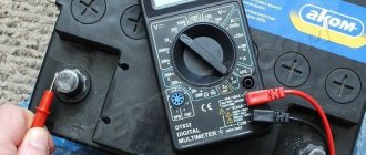
To check the stator of the angle grinder, use a multimeter, as in the previous case. The values need to be set to 20-200 Ohms and do the following. Touch one probe to the contact of the stator winding, and the second to the body of the part. If the device shows resistance, this means that a breakdown has occurred to the housing. Touch the probes to the contacts of one winding, and then to the contacts of the other. If the resistance is the same, then the coils are working. If the device shows an open circuit on one winding, it means that the stator will need to be rewinded or the part replaced with a new one.
Rewinding the stator at home without special knowledge, skills and equipment will be problematic. It is better to contact specialists who professionally rewind motors.
How to ring an armature with a multimeter
To carry out the inspection correctly, you need to know the operating mechanism and structure of the rotor. Its main structural parts are:
- a round core, which is a set of plates made of electrical steel;
- winding wound in a specific way into the grooves of the core.
Following a special scheme, two winding conductors are placed in any of the slots. Any of the conductors represents half a turn. Its ends are connected in pairs on lamellas. The end of the last turn and the beginning of the first are placed in one groove and closed by one lamella.
Before checking the armature with a multimeter, you need to carefully examine it for various damages:
- melted wiring;
- burnt insulating varnish;
- deformation of turns;
- the presence of conductive particles (such as solder residues), which often become a prerequisite for a short circuit;
- curvature of the curved edges of the lamellas (cockerels) connecting them to the winding, leading to burnout of the lamellas;
- accumulation of graphite from collapsing brushes between the lamellas, which also becomes a prerequisite for a short circuit.
Step by step instructions
Specifically, checking the armature with a multimeter occurs as follows:
- The probe connectors of the device are inserted into the appropriate sockets.
- Set the resistance measurement mode. Measurement spectrum – 200 Ohm.
- The probes alternately touch each 2 adjacent lamellas, recording the results displayed on the multimeter screen. You will have to ring each pair of adjacent plates in turn.
Mechanical breakdowns and their elimination
Mechanical failures of angle grinders include the following.
- Worn motor armature bearings. Typically, when the bearings wear out, you may experience strong vibration while the machine is operating. In addition, grinding and other noises may be heard. Sooner or later, the bearing will collapse, and the spilled balls will fall on the gears of the gearbox. If this happens, then in addition to the bearing, the gears will also have to be replaced. Of course, it is better not to wait for this problem, but to replace it at the first sign of bearing failure. How to get to this part of the angle grinder was described above.
- Worn ball bearing or plain bearing of the gearbox. As in the previous case, when you turn on the device, vibration will be felt and noise will be heard that is unusual for the normal operation of an angle grinder. To prevent further damage to the gearbox, it is necessary to replace the faulty part.
- Reducer gear wear. Gears wear out quickly due to insufficient lubrication. For the same reason, the gearbox heats up. It is necessary to monitor the condition of the lubricant inside the gearbox and change it if necessary. How to disassemble the gearbox was described above. You need to use lubricant specially designed for angle grinder gearboxes, and you can buy it at points where this tool is sold. If for any reason the teeth of at least one gear are broken, then the entire set of gears (a pair) needs to be replaced.
Mechanical faults can also include a broken shaft lock. In order to replace the retainer, you will need to disassemble the gearbox and remove the large gear.
Do-it-yourself Bosch grinder repair
Angle grinders (angle grinders, angle grinders) under the German brand Bosch are distinguished by high quality, reliability and durability. The main competitive advantage of Bosch angle grinders lies in the widespread use of innovative technologies in the manufacture of the product.
But German quality cannot resist Russian negligence. Incorrect use of the tool, untimely replacement of lubricant, carbon brushes, bearings leads to tool failure.
In order to repair a Bosch angle grinder, you can go in two ways: take the angle grinder to a service center or repair the Bosch angle grinder yourself.
The first option is more expensive and not always of high quality. The second option can only be implemented if the consumer has a strong desire to figure everything out on their own.
The Bosch angle grinder diagram will help you carry out the repair yourself.
Bosch grinders are conventionally divided into low-power ones up to 1000 W, and powerful ones over 1000 W and are marked GWS 7-125, GWS 20-230 or others.
The first number 20 or more indicates the power of the instrument is more than 1000 W. The second number 230 certifies that this is the maximum diameter of the cutting wheel.
The first number up to 20 indicates the power of the tool up to 1000 W, and the second indicates the maximum diameter of the cutting wheel up to 125 mm.
Design features of the Bosch angle grinder
A design feature of the Bosch grinder is represented in the use of a gearbox as a support bearing for the driven helical gear of a needle bearing. In Bosch rotary hammers, the driven gear is attached to the spindle shaft by pressing.
In low-power Bosch angle grinders, in which spur gears are installed in the gearboxes, the installation of shims is provided. This design allows you to restore the functionality of the gear contact by reducing the thickness of the gasket. At high tool speeds, helical gears wear out significantly less than spur gears.
The work environment for grinders is most often a dusty space. Dust is the main danger leading to failure of power tools, grinders and grinders.
Why does the grinder need low speeds?
The built-in disc speed control function allows you to delicately process materials such as plastic or wood. At low speeds, operating comfort and safety increases. This function is especially useful in electrical and radio installation practice, in car services and restoration workshops.
In addition, among professional users of power tools there is a strong opinion that the simpler the device is, the more reliable it is. And it is better to move the additional service stuffing outside the power unit. In this situation, equipment repair is greatly simplified. Therefore, some companies specially produce remote, separate electronic regulators that connect to the machine’s power cord.
Types of Voltage Regulators
Having understood what types of these devices there are, what their features and properties are, a complete understanding of the procedures carried out during testing will come. This will also give the answer to what scheme, in what way and how to check the generator voltage regulator. There are two types of regulators:
- combined;
- separate.
In the first case, it is meant that the regulator housing is combined with the brush assembly directly in the generator housing. In the second case, the regulator is a separate unit, which is located on the car body, in the engine compartment, and wires from the generator go to it, and wires from it go to the battery.
A special feature of the regulators is that their housings are non-separable. They are usually filled with sealant or special resin. And there is no particular point in repairing them, since the device is inexpensive. Therefore, the main problem in this regard is to check the generator voltage regulator relay. Regardless of the type of regulator, the voltage symptoms will be the same.
Tools needed for repairs
To repair a Bosch angle grinder, you cannot do without tools. Let’s make a reservation right away: if you have a screwdriver, this will significantly speed up the process of disassembling and assembling the tool.
But you can get by with a set of screwdrivers, preferably with a ratcheting mechanism. You cannot do without an open-end wrench, which you will use to unscrew the nut securing the drive helical gear.
To remove bearings, it is better to have a special puller.
Diagnostics of the electrical part can be carried out using a tester or a device for determining short circuits of turns.
It is especially useful in that it allows you to determine whether the rotor or stator is faulty without removing the assembly.
The Bosch angle grinder diagram will help you carry out the repair yourself, and these instructions will help you adequately cope with any problem.
Rotor assembly
Assembling the rotor consists of pressing bearings onto it and installing the impeller. Lubricated bearings are pressed onto the shaft using a wooden extension. The bearing near the collector is covered with rubber protection. This is the general algorithm for assembling the rotor shaft.
Some models of Bosch angle grinders have their own characteristics.
How to remove the drive gear of a Bosch angle grinder
The drive gear pos. 27 is removed from the rotor shaft in the following sequence:
- Hold the rotor with your hand and, using an open-end wrench, unscrew the nut pos. 45 counterclockwise;
- remove the washer pos. 59.;
- pull out the drive helical gear pos.27.
Visually check the integrity of the gear teeth and contact patch.
If the gears are heavily worn (licked), or there are chipped teeth, they must be replaced. Moreover, gears are always replaced in pairs.
Low-power Bosch angle grinders use a needle bearing as a support bearing in the gearbox.
When repairing Bosch angle grinders yourself, strictly follow the included instructions. If you need to remove a needle bearing from its housing, some quick thinking is required. Its dismantling is carried out only when destroyed.
To remove a damaged bearing race, you can use a proven method.
Select a tap with a diameter slightly larger than the inner diameter of the damaged needle bearing race. The tap is secured in the screwdriver chuck and carefully screwed into the holder at low speeds. When the tap reaches the bottom of the gear housing, it will begin to lift the cage.
In addition to the needle bearing of the spindle shaft, Bosch angle grinders use two more bearings mounted on the rotor shaft.
Assembling the grinder
The assembly of the grinder begins with an examination of all parts, assemblies, bearings, and gears.
Pre-prepare the workplace with proper and good lighting, place tools, lubricants, and napkins.
Do-it-yourself disassembly of a Bosch angle grinder
For the owner of a power tool, knowledge of its structure and the ability to disassemble it is a mandatory task.
Knowing the procedure for disassembling an angle grinder allows you to independently carry out work such as changing grease, changing bearings and carbon brushes.
To disconnect the gearbox housing pos. 821 from the stator housing pos. 888, you need to disassemble (remove) the body of the grinder handle pos. 24.
This operation must be performed to remove the carbon brushes pos. 810 holding the rotor commutator.
At the second stage, unscrew 4 (four) screws, pos. 61, securing the gearbox and stator housings.
Having pulled out the rotor together with the gearbox, begin disassembling the gearbox.
Repair of a Bosch angle grinder begins with disassembling the gearbox pos. 821. Disassembling the gearbox begins with unscrewing 4 (four) screws, pos. 60. As a rule, the screws are screwed in with sealant at the factory. You will have to make some effort.
Let's note it right away! Low-power Bosch angle grinders use spur gears in the gearbox. Grinders with a power of over 1000 W use helical gears in their gearboxes.
How to determine whether a rotor is faulty
Rotor repair is a complex technological process accessible to skilled craftsmen.
A rotor malfunction is indicated by a drop in engine speed and the appearance of a long sparkling trail on one of the brushes. This is the first sign of a short circuit in the armature winding turns.
It is preferable to carry out rotor repairs in special workshops. Or you can rewind it yourself if you decide to repair the Bosch angle grinder yourself.
The dark color of the rotor winding and burnt commutator lamellas indicate a short circuit in the rotor circuits. The malfunction can only be eliminated by replacing it with a new rotor.
Sources:
https://vahatehnika.com/boLGarka/kak-umenshit-oboroty-na-boLGarke.html https://toolparts.com.ua/novosti/proverka-iakoria-testerom-rekomendatsii-spetsialistov https://sdelalremont.ru/ remont-boLGarki-Bosch-svoimi-rukami.html
Electronic unit in an angle grinder
The electronic unit allows you to combine the speed controller and soft start into one. The electronic circuit is implemented on the principle of pulse-phase control with a gradual increase in the opening phase of the triac. Grinders of different power and price categories can be equipped with such a block.
If you have an old grinder among your tools, do not rush to get rid of it. Using a simple electrical circuit, the tool can be improved by adding the option of adjusting the rotation speed. Thanks to a conventional control device, which you can create with your own hands within a few hours, the functions of the tool will expand significantly. By reducing the number of rotations per unit of time, the angle grinder can be used as a sharpening and grinding unit for different types of materials. There will be additional opportunities for using auxiliary equipment and attachments.
Calibrating a new IAC
What should I do if the test reveals that the sensor needs to be replaced? It needs to be calibrated.
- We check the distance from the end of the rod to the mounting plate, it should be no more than 23mm.
- We disconnect the minus from the battery, de-energizing the ECU.
- Install the regulator.
- We connect the battery back.
- Turn on the ignition for 5 seconds without starting the engine. At this time, the IAC calibration occurs.
- Turn off the ignition to complete the calibration.
- We start the engine and observe the idle speed.
Now you know how the idle air regulator works, how to check it and, if necessary, replace it. As you understand, there is nothing complicated about this and all operations are accessible even to a novice car enthusiast.
Finally, a video about diagnosing IAC:
Previous post How to check gasoline injectors
Next entry Misfires - causes, diagnosis, elimination