An adapter such as SCART-RCA was very popular not long ago. As for televisions, VCRs and DVD players, not only all European-made equipment was equipped with a SCART connector, but much of the Asian equipment also had this connector. In Asian (Japan, South Korea) equipment, the mandatory switching connectors are composite RCA connectors, which are colloquially referred to as “tulip”.
The SCART-RCA connector has not completely lost its popularity even now, since many televisions are equipped with this connector, and there is no possibility (and need) to connect analog equipment to the TV. In addition, if you need to digitize from a VCR or from old cameras, then digital cords will not help you. There is a possibility that the SCART connector with the required pinout for your case will no longer be available for sale. However, you can assemble such a connector yourself.
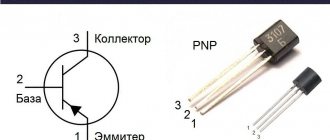
VGA connector pinout
The VGA video adapter is a three-row (each row has 5 pins) 15-pin connector. The picture below shows a modern 15 pin VGA DDC2 connector.
| Name | Designations |
| 1.Red | Red video (75 Ohm, 0.7 V) |
| 2.Green | Green video (75 Ohm, 0.7 V) |
| 3.Blue | Blue video (75 Ohm, 0.7 V) |
| 4.RES | Not used |
| 5.GND | Earth |
| 6.RGND | Land of red |
| 7.GGND | Land of green |
| 8.BGND | Land of blue |
| 9.+5V | Additional +5V from video card |
| 10.SGND | Earth Synchronization |
| 11.ID0 | Monitor ID Bit 0 (optional) |
| 12.SDA | I2C bidirectional data line |
| 13.HSYNC or CSYNC | Horizontal sync (or composite sync) |
| 14.VSYNC | Vertical Sync |
| 15.SCL | Clock frequency 15 SCL I2C in DDC2, Monitor ID3 in DDC1 |
Pinout
Scheme
SCART pinout (female)
| Pin no. | Group | Signal | General | Purpose (TV side) | Signal level (span), V | Input and output impedance | RCA connector color |
| 1 | Audio | Right OUT | 4 | Right audio output | 0.2—2 (0.5 effective) | < 1 kOhm | Green |
| 2 | Audio | Right IN | 4 | Right audio input | 0.2—2 (0.5 effective) | > 10 kOhm | Red |
| 3 | Audio | Left/Mono OUT | 4 | Left audio output (or mono) | 0.2—2 (0.5 effective) | < 1 kOhm | Black |
| 4 | Audio | GND | — | Common ground for audio channels | |||
| 5 | RGB | GND (Blue) | — | Ground for blue signal | |||
| 6 | Audio | Left/Mono IN | 4 | Left audio input (or mono) | 0.2—2 (0.5 effective) | > 10 kOhm | White |
| 7 | RGB | Blue | 5 | Blue signal input B | Spread 0.7 | 75 Ohm | |
| 8 | S&AR | Status & AR | 14 | Switching the TV to an AV source and setting the aspect ratio | 0—2 → TV5—8 → AV/9.5—12 → AV/ | input > 10 kOhm, output < 1 kOhm | |
| 9 | RGB | GND (Green) | — | "Ground" for green signal | |||
| 10 | Data2 | SCL | 14 | Data2 (I2C) clock line | |||
| 11 | RGB | Green | 9 | Green signal input G | Spread 0.7 | 75 Ohm | |
| 12 | Data2 | S.D.A. | 14 | Data2 (I2C) data line | |||
| 13 | RGB/S-Video | GND(Red/C) | — | "Ground" for red signal / Common C-channel S-Video | |||
| 14 | Data2/S&AR | GND | — | Data/Clock I2C, common | |||
| 15 | RGB/S-Video | Red/C | 13 | Red signal input/output R/C channel S-Video | Spread 0.7 | 75 Ohm | |
| 16 | FastSwitch | RGB Select | 18 | CVBS/RGB switching signal (FastSwitch), blanking signal | 1—3 (log “1”) → RGB 0—0.4 (log “0”) → CVBS | 75 Ohm | |
| 17 | CVBS/S-Video | GND(CVBS/Y) | — | Common for CVBS/Y-channel S-Video | |||
| 18 | FastSwitch | GND | — | Common for FastSwitch (pin 16) | |||
| 19 | CVBS/S-Video | CVBS/Y OUT | 17 | Composite Video Output / S-Video Y-Channel Output | Spread 0.7 | 75 Ohm | Blue |
| 20 | CVBS/S-Video | CVBS/Y IN | 17 | Composite Video Input / S-Video Y-Channel Input | Spread 0.7 | 75 Ohm | Yellow |
| 21 | Chassis | GND | — | Chassis Grounding |
Connectors
If the number of connectors that a SCART adapter can have directly depends on its class, then even a standard satellite tuner has three of them:
- the first is intended for connection to a TV;
- the second is used to connect players;
- the third provides the ability to connect a decoder for various “closed” programs.
For the latter, it is especially convenient to use a SCART connector. An adapter from any other cable of this type can also be used - through them the encoded signal will enter the decoder, and then return back in an “open” form. The situation is exactly the same with cable decoders of various paid programs, the use of which can now be carried out using a single cable of this interface.
Description RCA
| RCA plug |
|
RCA jack or composite (also called phono connector, or CINCH/AV connector, and also colloquially “tulip”, “bell”, AV connector) is a connector standard widely used in audio and video equipment.
The big disadvantage of such connectors is that when connecting, the signal contact pair (with voltage) is connected first, and only then the housing contacts. This can cause damage to devices at the time of connection if there is a potential difference between the cases, which often happened when connecting TVs to the TV output on video cards.
A standard RCA plug (in slang for “male”) looks like a central metal protruding contact pin with a diameter of 3.2 mm (3.18 for a 0.25 inch size), an outer open length of 9.0 mm (9.52/7. 92 mm for 0.375/0.312 inch sizes), with an internal closed length of 6.0 mm (5.56 for 0.219 inch size), surrounded by a metal round rim (8.0 mm minimum inner diameter; 8.33 for 0.328 inch size). The outer diameter of the rim depends only on its thickness and is not standardized.
The RCA (slang for "female") jack, typically a panel connector that the bezel fits over, has an outer diameter of 8.0 mm (8.33 for the 0.328-inch size) and a depth of 7.50 mm (7.14 for the 0.281-inch size). ), so the rim crimping jaws must have a slightly larger internal diameter.
In inexpensive versions, the space between the connector/collet and the rim/housing (internal insulator) is filled with simple plastic or polyethylene, in mid-price ones - with textolite washers or similar ones made of pressed fiberglass, in expensive ones - with heat-resistant Teflon or ceramics.
One of the main disadvantages of inexpensive connectors is their low heat resistance. Soldering cables with a cross-section of 0.823 mm² (18 awg) or larger requires a very long warm-up time at standard solder melting temperatures of 250 ° C - or much higher temperatures of the soldering iron tip, in order to increase the cumulative heat capacity of the tip, sometimes up to 500 ° C.
Design
Many people who want to make a SCART-tulip adapter with their own hands try to understand the design of this interface.
First of all, it is worth noting that there are 20 pin contacts in this connector, and the role of the 21st contact is assigned to a specialized metal screen, which is located along the entire perimeter of this connector. Its second purpose is to protect the contacts from any mechanical influences from the outside, and the mating part is made using plastic injection. It is worth noting that it can have not only lugs for self-tapping screws and screws, but also bosses intended for installation on printed circuit boards.
The design of cable connectors of this type can hardly be called original, however, there are three main types that differ from each other in the design of the housing - the cable can be routed straight, at an angle or to the side. The connector is held in the socket by specialized spring-loaded male contacts, thanks to which even the SCART-USB adapter is famous for its incredible reliability and fastener strength
Even such cables have to be inserted quite carefully so as not to move the device.
Getting to know the interface
So what is it? This is an interface recognized in Europe for connecting equipment such as a TV, game console, CD/DVD player, early models of computers, and VCR.
Now it is already somewhat outdated, although such an input can still be seen on the back panels of some devices. By the way, it often occurs on TVs.
The main feature of the interface is that it combines all the necessary signals for picture and audio playback in one plug. It consists of 21 contacts (20 signal lines and 1 protection line). The devices are connected naturally using a cable. The body of its tip has a curly bend, making it impossible to insert it incorrectly.
SCART connector. Description and pinout of SCART
The SCART connector (also called Peritel, Euro-AV or simply Euro-connector) is a special type of connector used in televisions and devices that are designed to work with it, such as VCRs, set-top boxes, DVD players and DVD recorders. This standard was created in France in 1977, and SCART became widespread in 1980.
This connector makes it easy to connect a variety of devices. It incorporates all the necessary signals (audio and video), which are output to a multi-pin plug. Today, almost every television or video device produced for Europe is equipped with a SCART connector. Analog and digital signals are exchanged through it.
SCART pinout
The SCART connector contains 20 pins, each of which can receive or transmit a specific analog signal. The metal edge of the connector (21 pins), as a rule, is connected to the shielding braid of the cable, which in turn helps protect the video signal from various interferences.
The outer metal frame is not symmetrical, which avoids incorrect connection of the connector to the socket. Below is the pinout of the SCART connector:
Pin 8 is designed to switch from an internal signal (TV) to an external signal source and has three levels:
- 0…2V (nominal 0V) – TV mode
- 5…8V (nominal 6V) – widescreen mode (16:9)
- 9.5… 12V (nominal 12V) – normal mode (4: 3)
Pin 16 is used to switch the TV from RGB to Composite mode and vice versa:
- 0...0.4V - composite video signal
- 1…3V (nominal 1 V) – RGB video signal
The RGB signal is mainly used to connect high-quality audio/video devices, such as a satellite receiver, to ensure the highest possible image quality. The RGB line only works as an input.
The big advantage of the SCART connector is that it includes three video standards:
- S-Video (contacts 15:20),
- Composite video signal (pins 17/19 or 18/20)
- RGB (pins 5, 7, 9, 11, 13, 15)
So you can assemble a simple adapter, for example, RGB-SCART, VGA-SCART, simply by connecting the corresponding pins. In addition to this, the SCART connector has pins for audio signal (pins 1, 2, 3, 4 and 6).
The main disadvantage of the SCART connector is significant signal loss as the cable length increases. In theory, each individual wire of a cable carrying a useful signal should have a braided shield, which is actually rare, since this significantly thickens the cable itself and makes it more expensive.
Another disadvantage is the fact that the data transmission density compared to current digital interfaces such as DVI and HDMI cannot be compared.
But still, thanks to its versatility, the potential of the SCART connector has not yet been exhausted.
www.joyta.ru
Description of the purpose of some pin groups
SCART is equipped with multifunctional outputs; when different voltages are applied, the execution device can be switched to different modes. For example, if there is a 0-2V signal on pin 8, it switches the TV to normal TV operation mode from an external antenna. When a 5-8V signal is applied to this pin, a widescreen mode for displaying pictures on TV is established. And a nominal voltage of 9.5-12V indicates the normal aspect ratio mode.
There is also a multifunctional pin numbered 16. With its help, one of two reception modes is selected: composite signal, RGB . The first requires a signal of no more than 0.4V, and to receive a color-difference signal from 1 to 3V.
The versatility of the connector lies in supporting three operating modes simultaneously:
How to connect video to domestic TVs
The lucky owners of the Japanese or South Korean miracle soon came to the conclusion that our televisions could well be used to watch foreign video programs. Most Soviet devices, modern at that time, already had all the necessary devices for connecting video equipment, namely: a built-in PAL-SEKAM decoder and a SCART connector on the back cover. They were also equipped with remote control or had the ability to easily install the necessary boards, control modules and infrared signal photodetectors. A shortage immediately arose for the appropriate connecting cables, which was readily filled by numerous cooperatives and private enterprises.
Contact distribution
The SCART connector is equipped with several groups of contacts that provide transmission of certain signals from the TV and back:
- 5 lines for transmitting and receiving audio;
- 9 lines for receiving and transmitting video signals;
- 2 lines for selecting modes;
- 3 lines for digital data transmission.
All lines are marked in different colors, which greatly facilitates the process of installation and connection of various devices. SCART is still very popular among a large number of users.
The scart implemented the ability to transmit stereo audio signals, which was later transferred to other more modern types of HDMI connectors. Due to the design features of the connector, data transfer is possible when controlled remotely. You can also connect unmodulated signals:
- composite;
- component;
- S-Video.
Component video signals include RGB and YPbPr. And S-Video includes 2 lines. The function of switching video signal reception modes and waking the TV from sleep mode upon command from an external device was added to the connector only in the late 80s. In the same years, SCART was supplemented with 2 video signal transmission lines S-Video.
Although the interface is large and inconvenient, many manufacturers still install it in their equipment with the expectation of using it to connect to old TV receivers. And in order to connect other types of devices to it, for example, a video camera, you will need a special adapter.
gslider srcs=»https://instanko.ru/wp-content/uploads/kak-podklyuchit-resiver-k-televizoru-cherez-skart4.jpg,https://instanko.ru/wp-content/uploads/perehodnik- vga-scart.jpg,https://instanko.ru/wp-content/uploads/404935.jpg,https://instanko.ru/wp-content/uploads/kak-podklyuchit-resiver-k-televizoru-cherez- skart3.jpg,https://instanko.ru/wp-content/uploads/kak-podklyuchit-resiver-k-televizoru-cherez-skart2.jpg"]
Application
SCART unifies the connections between different devices; it combines all the necessary signals in one multi-pole plug. Most LCD/LED TVs available in the market are equipped with at least one SCART connector.
Through SCART it is possible to transmit analog and digital commands. For example, if you turn on the VCR, the TV automatically turns on. The CEC video equipment control protocol, transmitted via the SCART connector, has made it possible to simplify the setup of various equipment using one remote control. For example, you can use your TV remote to program your VCR to record at a specified time from your satellite or cable digital receiver.
The design of the connector makes it impossible to connect the plug incorrectly. The disadvantage of the connector is that it requires physical force to connect and disconnect it.
SCART connector
SCART connector (“Syndicat Français des Constructeurs d'Appareils Connector Radio et Télévision” from French “Association of the Radio and Television Industry”). An analog signal connector, SCART is a physical and electrical connection between two pieces of audiovisual equipment, such as televisions and VCRs, DVD players, and audio equipment. SCART was designed to eliminate confusion with wires and connectors. Developed by Peritel in France and also known as the "EURO connector", the SCART cable uses 21-pin male connectors at both ends. Today, most new televisions and VCRs in the European market and other countries that use the PAL video standard are equipped with a SCART connector.
Bidirectional
Composite video and analog lines are bi-directional, allowing pay TV and teletext to be sent from the TV to the set-top box for decoding and then back to the TV.
What is scart on TV
The scart connector is needed so that you can easily connect other devices to the main information receiver. Video and audio signals come from it through the plugs. Today, almost all televisions are equipped with scart connectors. With their help, incoming digital and analog signals enter the device to reproduce images and sounds.
A scart port consists of twenty pins, each of which transmits or receives a specific signal. The edge of the scart, covered with a layer of metal, is the 21st pin, and is connected to the shielding braid of the cable. This design protects transmitted signals and neutralizes various types of interference.
Connector pinout
Even such an attractive connector as SCART cannot be used indefinitely. It was replaced by an S-Video connection. It is still widely used in various technologies. To connect to SCART, you can use widely used adapters. The wiring diagram is shown in the picture below.
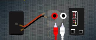
But an even simpler solution is becoming more widespread - RCA. Separate connection involves the use of yellow, red and white plugs. The yellow and white lines are responsible for stereo audio. The red channel supplies the video signal to the TV. Wiring into “tulips” is carried out according to the diagram shown in the following photo.
Quite often you have to solve another problem - how to connect the old connector and modern HDMI. In this case, you won’t be able to limit yourself to conductors and adapters. You will have to use a device that will “translate” HDMI digital signals into analog and vice versa. Independent production of such equipment is impossible or extremely difficult.
It would be best to buy a ready-made converter of an industrial standard; it is usually small in size and can be easily placed behind the TV.
For SCART connectors, see below.
Scart to HDMI adapter
If the scart connector can be converted to a tulip or S-Video, then one conductor will not be enough when implementing the same manipulation to obtain an adapter for HDMI. The fact is that HDMI is a digital interface, and analog signals come out of the scart. Therefore, the adapter must be able to convert one signal to another. Special converters are used for this, so it will be difficult to make such a device yourself. It is much easier and safer for yourself to buy a ready-made scart-HDMI adapter with a power supply. The device is implemented in a small case that easily fits in the palm of your hand, so it does not require much space to be placed on the back of the T-receiver.
Those annoying 20 contacts and ground
As a rule, the connecting cord was a cable, on one side of which there was a SCART connector, on the other, two, four or six contact groups of the American standard RCA (called “tulips” for their specific shape). At its core, it was a simple adapter that allowed for galvanic connection of the source with a video monitor (TV). Owners of video equipment often cursed, cursing the imperialists for the lack of desire for universal standardization, believing that 21 contacts for such a simple device was too many.
Only television specialists, for whom the SCART connector diagram did not constitute a “Chinese letter”, were able to appreciate the full potential of this approach on the part of the French Union of Electronics Manufacturers, in honor of which it received its name (Syndicat Des Constructeurs D'Appareils, Radiorecepteurs Et Televiseurs - SCART).
(1 rating, average 5 out of 5)
What it is?
It is quite easy to answer the question of what SCART is on a TV. This is one of the connectors designed to ensure that the television receiver is used in close conjunction with other devices.
It is equally important that the domestic radio-electronic industry quickly picked up this idea. Already in the 1980s, SCART was used very widely
These ports were connected to in different years:
- video recorders;
- DVD players;
- set-top boxes;
- external audio equipment;
- DVD recorders.
But at the initial stage of its development, SCART was not perfect enough. Even the most advanced developments of this kind in different countries suffered from interference. Remote control often caused difficulties. And for a long time it was not possible to ensure the production of cables of the appropriate standard in the required quantity. Only by the mid- or even late 1990s were SCART’s “childhood diseases” defeated and the standard gained the trust of consumers.
Nowadays such connectors are found in almost all manufactured TVs. The only exceptions are certain models that focus on newer versions of interfaces.
The port is divided into 20 pins. Each pin is responsible for a strictly defined signal. In this case, the perimeter of the SCART port, covered with a layer of metal, is conventionally considered the 21st pin; it does not transmit or receive anything, but only cuts off interference and interference.
The 8th pin is designed to transfer the internal signal of the TV to an external signal source. Using pin 16, the TV changes the composite mode to RGB or switches back. And pin inputs 15 and 20 are responsible for processing the S-Video standard signal.
SCART pinout
The abbreviation SCART (Syndicat des constructeurs d”appareils radio recepteurs et televiseurs) is translated from French as “Association of the Radio and Television Industry”. The European unified connector, developed at the very beginning of the eighties, was intended for connecting various devices: a TV with a printer in the Videotext system, a keyboard in the Teletext system, VCRs, video players and Hi-Fi devices, a home computer, etc. The SCART connector is used not only in all European-made devices, but also in most Japanese devices.
Scart pinout - correct pinout
Scart pinout - in the early 80s, the French joint company of radio and television developers designed a multi-pin SCART connector. Using this audio-video interface, it became possible to broadcast data received from RGB signal sources. This device, which provides excellent video quality, quickly became a fairly popular connector in Europe.
Read also: What do lathes and drilling machines have in common?
Somewhat later, this 21-pin connector found its application in players and video recorders produced by famous world brands. There are currently many popular systems for exchanging information using SCART.
In terms of design, the connector was developed to perform switching of various types of data in digital and analog format. This includes the transmission of audio and video signals, with the help of just one such connector it has become possible to record and play video content. In addition, a command transmission function is available to control the multimedia device during its setup.
Design features and scart pinout
The pinout of the scart connector is made according to a 2-component asymmetrical circuit; double-row spring-loaded male contacts transmit signals (20 are signal paths and 1 for protection). The outer housing of the contact connector has a characteristic shape that serves as a kind of key. It is this structural protrusion that guarantees the correct connection of the SCART; if it is unfolded during connection, the connection will be impossible.
The pinout of the SCART connector is carried out by installing odd numbers of contact blades at the bottom of the connector, while the cable key will be on the right side. The upper row of contacts, which have even designation numbers, is made with some offset relative to the lower row. It is this arrangement of the “knives” that prevents the connector from being connected in the opposite direction. The order of signal data through the contacts is shown in the table below. The protective wire, placed in a braided shield, is connected to 21 contacts.
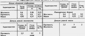
| Contact no. | Purpose | Signal level, circuit resistance |
| 1 | Right channel audio output (mono) | Veff. = 0.2-2.0V, R 10kOhm |
| 3 | left channel audio output | Veff. = 0.2-2.0V, R 10kOhm |
| 7 | “BLUE” signal input/output | swing 0.7 V VDC = 0-2.0 V, R=75 Ohm |
| 8 | TV/VIDEO switching voltage input/output | Voff = 0 - 2.0 V, Von. = 9.5 - 12V, Rinput. > 10kOhm, Rout. Making a SCART cable with your own hands |
The need to manufacture a connector with a SCART connector at home may be caused by the need to create a multimedia complex for the home. And the pinout of the scart connector is done according to the table presented. When making a SCART connector yourself, it is not necessary to use all the contacts; you can connect only the ones you need. The place where the wire is soldered to the contact should be placed in a casing, possibly with heat-shrinkable properties.
SCART, as a unified connector, was first introduced by a French company. It was created to optimize signals from devices from various manufacturers. Thanks to the creation of a single format, users had the opportunity to buy models of household appliances from different brands, thereby allowing them to make a choice in favor of comfort, convenience, reliability and practicality.
Read also: Device for sharpening drills at home
The introduction of the universal connector was carried out intensively, by banning, starting in 1981, the production of equipment with other types of connections. The new format was introduced as mandatory for all manufacturers without exception. But at the same time, SCART began to be actively used throughout Europe only 3 years later, becoming a standard regulated by EN 50049-1. Due to its format and design, the connector has received many common names, such as comb and ratchet.
Technology and development
For those who are interested in the technical side of the issue, I’ll tell you that initially several signals were combined in scart:
- Composite (low frequency, unmodulated);
- Video (input and output);
- RGB (red, green, blue video signals);
- Bidirectional "input-output";
- Stereophonic;
- Digital (all of the above are analog).
With just one cable, it became possible to simultaneously play sound, image, record video and connect to an RGB source. This provided the highest quality picture at that time. By introducing a digital signal, it became possible to change the screen proportions, control turning equipment on and off, etc. In short, it was cool :).
A few years after its introduction, the standard received new control commands. For example, I “learned” how to wake up the TV from sleep mode or switch the method of receiving a video signal.
By the way, a component (on line 2) S-Video video signal was also added to it, where the first letter hides the word “Separate”. It broadcasts 2 signals - brightness and chrominance. I’ll make a separate post about it someday.
Later, some manufacturers of equipment with this interface began to replace RGB (analogue) with YСbСr (digital), but this was not accepted as a standard.
After so many years and in our time, SCART does not want to leave the market. Due to the fact that modern equipment is equipped with HDMI connectors, special adapters have appeared that convert the outdated standard to the new one. They are not cheap, but they can significantly improve the image - the maximum resolution is 1080p.
I bought just such a thing for myself, in the future I will also write about it in more detail, because the device is quite interesting and useful.
I will end here. I think it’s now clear to you what a scart connector is.
Please know that you are always welcome on this blog.
Connectors
Most models of TV set-top boxes have a large number of connectors and interfaces. Of course, it would be easier to equip the device with one universal output for convenience, but not every home has a TV, for example, with a modern HDMI interface. Yes, such an output is capable of transmitting video and audio signals as correctly as possible, but such models are not cheap and not everyone can afford them.
Some people still can’t part with their “ancient” TVs, so many TV set-top boxes are burdened with versatility for the sake of convenience. However, before purchasing a set-top box, it would not be superfluous to check whether it has one or another connector/interface for your TV. Also keep this in mind before connecting your TV to the receiver.
Why is it so difficult? But why!
Unlike conventional “tulips”, the SCART RCA connector has a number of advantages that provide extensive control capabilities, better color reproduction and even digital broadcasting, unthinkable in the early 80s (it was developed in 1983).
Today, even consumers who are little educated in electronics know that the variety of colors on the screen is created by only three components: red, green and blue. Their separate supply to the color module eliminates a number of interferences and makes the picture clearer. This opportunity is provided by the SCART connector, in which the 7th, 11th and 15th pins are designed to supply an RGB signal, and the 5th, 9th and 13th, alternating with them, are intended for shielding shells.
But this is not all the capabilities that the SCART connector has. The pinout assumes the ability to automatically turn on and off the TV simultaneously with a low-frequency signal source (DVD or VCR), regardless of which company manufactured the equipment. The widescreen display mode also turns on independently.
In addition to these functions, there are two digital contacts - the 12th and 14th, prophetically identified by French engineers back in 1983, when almost all consumer electronics were analog. There is also a connector for connecting a timer, it is number ten.
So, 20 contacts and one common one (21 in total) - this turns out to be not so much. For modern entertainment video centers they are still sufficient, although they are no longer enough to enable Dolby Surround...
Article rating:
What is a scart connector on a TV Link to main publication
Related publications
How to properly connect current transformers to the meter
Pros and cons of TVs with a scart port
Connecting a computer to a TV via an RCA cable
The advantages of TVs with a scart port include:
- High quality color images.
- Great control possibilities.
- Clarity of pictures, since colors are transmitted separately, through the appropriate contacts.
- The connectors are coated with a special agent that helps eliminate interference.
- Using pinouts, it is possible to automatically turn on/off the television receiver and additional equipment simultaneously. For example, if you turn on a tape recorder or other device that is connected to the TV, they will start working together.
- Possibility to enable automatic widescreen image function.
The scart connector also has some disadvantages:
- With a very long cable, the signal is gradually lost until it reaches the desired point.
- To make the signal clearer, the braiding on the wire must be shielding. This means that the cable, in this case, will be too thick, and this is not entirely convenient.
- More recently, new DVI and HDMI interfaces for digital data transmission have entered the market, with a density much higher than that of a scart port.
- The scart connector cannot be used to connect some modern video entertainment centers, for example, such as Dolby Surround. To enjoy this privilege, more advanced special equipment is required.
- The quality of functioning of the scart connector depends directly on the type of television receiver. Plasma liquid crystal devices transmit high quality signals. But TVs equipped with a kinescope are too far from this and cannot boast of good data transmission, even modern models of this type.
- Not all types of video cards have the ability to support connections to scart ports. This paragraph applies exclusively to computers.
But, despite these disadvantages, scart connectors are still installed on many TVs.
Do-it-yourself tulip usb adapter diagram
- How to make a vga adapter tulip
- How to transmit a signal
- How to make a tulip
Internet, very old video card with support for tv-out over d-sub, d-sub m connector, rca connector, 75 Ohm coaxial cable, soldering accessories
The easiest way to connect a TV to a computer is a video card with a separate TV-out, tulip or s-video.
You can also use a converter.
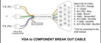
Perhaps another way to connect your computer to your TV will suit you, for example: - connecting with a vga vga cable, if your TV has a vga input. Some modern TV models are equipped with a special adapter for connecting vga; - connection via a vga s-video adapter. This connection is possible on some models of ATI Radeon video cards, for example, the 3000 series, and with special settings for the video card driver. The TV must also have an s-video input; - connection via a vga YPbPr adapter. The same as in the previous paragraph, but the TV must have a YPbPr component input (three non-yellow tulips); - connection via a vga SCART adapter. The same as in the previous paragraph, but the TV must have a SCART input (comb).
I have a prology hdtv-850wns TV, it has a USB connector, but it’s not an ordinary connector, through it you can send video and audio signals, that is, a signal input... You need a cable for this, but there isn’t one, who knows the circuit diagram for such an adapter ? Or maybe you can tell me which foot to send the video signal to in the diagram? I’m just not good at schematics, so I could figure it out myself...
Thank you, I got the TV with a dead lamp backlight, I converted it to LED from the laptop, but I just want to watch movies on it...
Comments 29
Determining the pinout is a 5 minute question. You need a datasheet for the microcircuit and a little intelligence.
Even though it was a long time ago, did you find the diagram? If yes, please share or link to Ali?
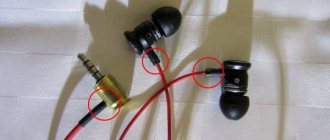
There is also such a TV. I took a Usb cord from an external hard drive, cut off a mini-Usb and at random found a video signal and sound and then soldered it with another cord at the end of which there were tulips.
I have the same principle on Mystery. This USB is just similar to the regular one, but has nothing in common with it. It does not have stereo sound, video tulip and audio tulip. There is no power supply there, the 12V socket is separate.
We know, I almost burned the flash drive
I have the same principle on Mystery. This USB is just similar to the regular one, but has nothing in common with it. It does not have stereo sound, video tulip and audio tulip. There is no power supply there, the 12V socket is separate.
Well... I didn’t write it quite correctly - the connector here is just a real USB, physically, but not electrically))) You can solder anything there, even output 220 for example.
I wrote the same thing))) similar in appearance, inside (electrically) - nothing in common))) p.s. Is the glass half full or half empty? )))).
half whiskey, half cola! )))
Oh, order on Aliexpress and don’t worry... It costs a penny. For example, ru.aliexpress.com/item/1-...Cable-USB/1409419824.html
long wait, I wish I had ordered it
The parcel takes 2 weeks
not two, I order periodically from Ali, and parcels arrive at least 4 weeks...
I ordered the last 6 parcels, they arrived in two weeks, and 6 different ones)
compared Kazan and Baikalsk
in theory, not as long as usb is actually used as just a connector, and has nothing in common with usb itself
not in theory, but it is true. It’s just that the Shanghainese haven’t come up with anything better than adding a USB connector for switching audio and video signals.
Judging by the diagram, the video signal from TWO video inputs (USB pins No. 2 and 3) goes to the 4053 chip (this is a multiplexer/demultiplexer - a switch of digital and analog signals), and there the video input is selected (control contacts No. 9 and 10 of the chip , signal AV12). The sound comes through pin 4, pin 5 is common (GND), pin 1 is (+12 volts). And in the instructions this connector is described as follows: 14. “A/V” connector for audio/video input, additional power supply. To this connector you can connect the included cable with standard RCA type connectors and a power connector: Yellow RCA connector Video input No. 1 Red RCA connector Video input No. 2 White RCA connector audio input Power connector 12 V external contact - negative polarity internal contact - positive polarity
Those who own a significant amount of audio and video equipment are faced with a choice: make it yourself or purchase an adapter from the store that will convert signals of different types. Needless to say, factory devices cost a lot, but you can often do without them. And within the article we will talk about how to make a VGA to RCA adapter. Frequently asked questions will also be answered.
SCART adapter: types and description
After its first appearance, the SCART adapter caused, to put it mildly, mixed impressions among most users. The fact is that such connectors suddenly began to be used on modern televisions or tape recorders, while the vast majority of residents of the CIS countries were accustomed to using standard “tulips”. Of course, today this situation will make many people smile.
It is worth noting the fact that the main reason why the SCART adapter did not become widespread at that time was not even the fact that few people knew about it, but also the banal lack of corresponding cables on sale. Today you can buy any cable product on almost every corner, but in those days their cost was quite high.
The SCART adapter is a 21-pin connector with which users can connect different types of TVs and media devices. After its appearance, this interface won the hearts of most European consumers. Manufacturers of consumer media equipment immediately began using it in their devices. It is worth noting the fact that the developers of this standard were very far-sighted, because their device is still actively used by leading companies to this day.
Just 10 years ago, almost every video or television device that was manufactured for the European market was equipped with at least one such connector. So to connect media equipment to the TV, the user had to buy a SCART adapter. The reason this connector is so widespread is its versatility. Despite the fact that it is provided rather straightforwardly, that is, due to the number of contacts, the interface, although it has many negative aspects, is quite convenient.
First of all, it is worth noting the fact that with the help of one single cable, users can record or play back various video programs. This advantage was immediately appreciated by manufacturers of home computers, and over time, also by game consoles.
It is also worth noting the fact that the quality of sound and image supplied through the SCART adapter is noticeably better compared to the signal from a standard RF modulator. At the same time, we should not forget that the RF modulator does not provide for the possibility of transmitting stereo sound, introduces extraneous noise, and also requires extremely precise tuning of the TV.
Additional features
However, this turned out to be not enough, as a result of which the developers also included a large number of potential features in the interface, reserving space for new functions for the future. Since the time when the VGA-SCART adapter became one of the most popular in Europe, this standard has only just begun to acquire new properties. For example, using this interface today, you can control various TV modes, such as switching it to monitor mode and back, switching the mode of working with RGB signals, and much more. Moreover, these capabilities were previously very simple, while today SCART has the ability to transmit digital data, as a result of which the total number of commands has become almost unlimited.
Today you can find a large number of systems that provide information exchange using SCART, as a result of which the VGA-SCART adapter, as well as many others, have become very popular.
Cool Features
It is worth noting several interesting functions that have become available through the use of this interface.
Once you turn on the DVD player (or tape recorder, as it was originally), the TV automatically turns on as well. At the same time, if while watching a certain television program you have a desire to record it, you start recording this program with a single click. The FollowTV feature gives users the ability to “overwrite” tuner settings from their TV to their media device. It also provides control over the operation of devices through the TV screen and automatic selection of the most optimal image format. After the playing recording ends, not only the player, but also the TV itself turns off, which is also customizable and is a very, very interesting function.
Distribution of the new format
The French connector received universal approval and became the same for almost all European and Japanese manufacturers, which is why it is still used to this day to equip various household and specialized equipment, in particular, televisions:
- video recorders;
- TVs;
- DVD players;
- digital TV set-top boxes;
- special video editing equipment and much more.
The universal connector is easy to maintain due to the separation of contacts over fairly large distances, which greatly simplifies the process of diagnosing signals and performing other manipulations. The main feature of the scart is that when using it, the connection error factor is completely eliminated. What does its special asymmetrical body shape indicate? The universal French connector is still used today as the main one for many types of equipment.
The site editors advise you to familiarize yourself with the most popular WAGO terminal blocks from the company’s official website.