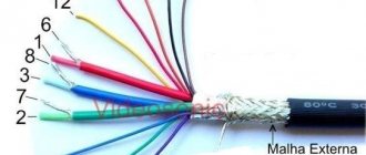
A large number of different connectors are used to connect blocks and assemblies of electronic equipment. Some connectors can contain dozens of pins. To connect most blocks into a single unit, structures with only two contacts are used. One is information or signal, and the other is general or “ground” and is designated in the diagrams as “GND”.
What is a "tulip"
This is a type of connector that is located at the end of a cable. It also serves as a marker, since it is painted in any color. Usually these are: red, yellow and white. It is by color that “sockets” for connection are found. You can also hear another name: “bells”. They are used to connect various devices to the TV:
- audio and video equipment;
- game consoles;
- DVD player;
- VCR.
Other connection methods use a SCART or coaxial cable.
Scart-tulip adapter
Today there are many devices equipped not with S-Video, but with an even simpler split connection type, consisting of 3 simple plugs in yellow, white, red . Everything is simple here: yellow and white are lines for transmitting stereo audio, and red is for supplying a video signal to the TV. The plugs are two-pin tulip connectors with a thick central pin and an outer shield. The adapter is wired according to the diagram shown in the photo.
Instructions for connecting the connector to the TV
The process of inserting connectors is called analog composite wiring. A 3xRCA cable is used, which is combined from 3 wires, interchangeable. But if the device has outputs suitable for an HDMI connection, it is better to connect with an HDMI cable.
Modern TV models have special composite inputs for “tulips”. They are painted in colors corresponding to their connectors:
- Red (provides signal transmission. Designed for the right channel).
- Yellow (activates video signal).
- White (provides audio or mono signal from the left channel).
The algorithm of actions is not particularly complicated; the plugs are inserted into the appropriate inputs, marked with the appropriate color.
Connecting tulips to a TV can happen this way. There are models in which all inputs have the same color. Then the following steps should be taken:
- find a group of “tulips” with an “IN” sign or two arrows;
- find the corresponding group on the device itself, with the sign “AV2” and connect the beam;
- determine the purpose of the connectors on the TV using the following signs: “V” (video), “L” (input on the left for audio), “R” (input on the right for audio).
How to properly connect tulips to a TV? Models with 2 connectors support only the mono sound function. Yellow and white are connected here. Red remains unattached.
It should be noted that the screens must have a small diagonal size when connecting “tulips”. Otherwise, the image will be blurred and show a fuzzy picture.
To configure and connect an external device, you should:
- Connect the wires to the external device (player, set-top box): yellow to the video output, the other to the audio output.
- Connect the wires to the TV: yellow to the VIDEO connector (“Y”). White and red in AUDIO connector (“L” and “R”).
- Find the designation “AB” (on the remote control you need to press SOURCE. In the designations that appear, click on “AB”).
- Check the power supply of the connected device (it should be turned on).
- Wait for the signal to appear on the TV screen.
- Use the remote control of the connected device for control.
- If there is no picture or sound, you should double-check all steps to find the error.
On different models, the inputs may be in different places. Some models can only be connected using an adapter.
Scart pinout - correct pinout
Scart pinout - in the early 80s, the French joint company of radio and television developers designed a multi-pin SCART connector. Using this audio-video interface, it became possible to broadcast data received from RGB signal sources. This device, which provides excellent video quality, quickly became a fairly popular connector in Europe.
Read also: DIY press machine
Somewhat later, this 21-pin connector found its application in players and video recorders produced by famous world brands. There are currently many popular systems for exchanging information using SCART.
In terms of design, the connector was developed to perform switching of various types of data in digital and analog format. This includes the transmission of audio and video signals, with the help of just one such connector it has become possible to record and play video content. In addition, a command transmission function is available to control the multimedia device during its setup.
Design features and scart pinout
The pinout of the scart connector is made according to a 2-component asymmetrical circuit; double-row spring-loaded male contacts transmit signals (20 are signal paths and 1 for protection). The outer housing of the contact connector has a characteristic shape that serves as a kind of key. It is this structural protrusion that guarantees the correct connection of the SCART; if it is unfolded during connection, the connection will be impossible.
The pinout of the SCART connector is carried out by installing odd numbers of contact blades at the bottom of the connector, while the cable key will be on the right side. The upper row of contacts, which have even designation numbers, is made with some offset relative to the lower row. It is this arrangement of the “knives” that prevents the connector from being connected in the opposite direction. The order of signal data through the contacts is shown in the table below. The protective wire, placed in a braided shield, is connected to 21 contacts.
| Contact no. | Purpose | Signal level, circuit resistance |
| 1 | Right channel audio output (mono) | Veff. = 0.2-2.0V, R 10kOhm |
| 3 | left channel audio output | Veff. = 0.2-2.0V, R 10kOhm |
| 7 | “BLUE” signal input/output | swing 0.7 V VDC = 0-2.0 V, R=75 Ohm |
| 8 | TV/VIDEO switching voltage input/output | Voff = 0 - 2.0 V, Von. = 9.5 - 12V, Rinput. > 10kOhm, Rout. Making a SCART cable with your own hands |
The need to manufacture a connector with a SCART connector at home may be caused by the need to create a multimedia complex for the home. And the pinout of the scart connector is done according to the table presented. When making a SCART connector yourself, it is not necessary to use all the contacts; you can connect only the ones you need. The place where the wire is soldered to the contact should be placed in a casing, possibly with heat-shrinkable properties.
SCART, as a unified connector, was first introduced by a French company. It was created to optimize signals from devices from various manufacturers. Thanks to the creation of a single format, users had the opportunity to buy models of household appliances from different brands, thereby allowing them to make a choice in favor of comfort, convenience, reliability and practicality.
Read also: As10d31 DIY repair
The introduction of the universal connector was carried out intensively, by banning, starting in 1981, the production of equipment with other types of connections. The new format was introduced as mandatory for all manufacturers without exception. But at the same time, SCART began to be actively used throughout Europe only 3 years later, becoming a standard regulated by EN 50049-1. Due to its format and design, the connector has received many common names, such as comb and ratchet.
Problems that may arise during work
How to connect tulips to a TV? Sometimes, after connecting, problems may arise. They begin to appear immediately. Among the most common are:
- disconnecting the cable (the plug came out of the hole);
- burnt-out electronics (to avoid such a nuisance, the connection is made with the TV turned off);
- no image (connector inserted in the wrong place);
- there is no yellow connector on the TV (there may be a blue, white, green, two red. In this case, when connecting a digital set-top box, you should go to its settings and mark the color system “PAL” or “SECAM”);
- the device does not have inputs and outputs for “tulips” (you can purchase an adapter);
- when connecting to a VCR, there are no colors corresponding to the “tulips” on the TV (you should take the “OUT” signal from the connected device. On the TV, find a group of “tulips” responsible for “IN”. Before connecting, you should press “AV” in the TV menu);
- If you start the connection not from the ground, but from the signal wires, then due to the potential difference between the grounds, you can destroy the interface.
If you are careful and follow safety precautions, many troubles can be avoided. The best option would be to invite a specialist who will professionally and quickly solve the problem.
Entrance/exit “Tulip”
When choosing connectors for connecting cables, you need to pay attention to the manufacturer. Products from some companies from the Asian region are of poor quality. The use of low-quality plastic in the connector design leads to the fact that the central rod, to which the signal wire fits, loses the rigidity of its fixation. This results in an alternating contact in the connection. It is better to choose connectors with a textolite or ceramic core. The screw clamp is an unreliable connection. It is best when the wire is fixed by soldering. Product bodies made of plastic are used only in budget cables. Reliable RCA connectors have metal housings.
How to connect tulips to a TV?
Modern audio and video equipment is connected to the network using a variety of connectors and cables. All these cables have specific names and types, as well as special color markings. Let's look at the most used tulip-type connector and figure out how to connect tulips to a TV.
What kind of connector is a “tulip”?
This type of connector is also called composite, or RCA, CINCH/AV connector, etc. This type of connector is popularly called “tulip” or “bell”. This type of connector is widely used for audio and video equipment: VCR, DVD player, game console and other devices.
Coaxial cable, SCART cable and others can also be used for connection. But it is worth noting that this type of device connection, such as a tulip, or RCA, provides the best picture and sound quality.
To determine the type of signal traveling along the cable, a standard color scheme is used, in which each of the colors of the plug corresponds to a specific signal. The most common types of signals and their colors can be seen in the table below.
How to connect a tulip to a TV
Today, every TV is equipped with a special composite tulip connector.
Basic color signals:
- yellow – for video signal,
- white – for left audio signal or mono signal,
- red – for signal transmission, respectively, for the right channel.
Connecting a tulip to a TV is a fairly simple procedure in itself. To do this, simply connect all the tulip plugs, which are designated by colors, to the corresponding inputs on the TV.
It happens that a TV has many inputs with the same colors. In this case, follow the instructions below.
So, to connect an RCA cable, or tulip:
- We find a group on the bundle of wires, which is designated by the word IN (translated from English as “in”), this group of cables can also be designated by a symbol (two arrows);
- We find the same group on TV. It will be designated as AV2. We connect the beam to the TV;
- At the TV input we see that each of the connectors is also labeled:
- the letter "V" means video connection (i.e., image);
- the letter L indicates the left audio input;
- letter R – right audio input.
Scart to HDMI adapter
If the scart connector can be converted to a tulip or S-Video, then one conductor will not be enough when implementing the same manipulation to obtain an adapter for HDMI. The fact is that HDMI is a digital interface, and analog signals come out of the scart. Therefore, the adapter must be able to convert one signal to another. Special converters are used for this, so it will be difficult to make such a device yourself. It is much easier and safer for yourself to buy a ready-made scart-HDMI adapter with a power supply. The device is implemented in a small case that easily fits in the palm of your hand, so it does not require much space to be placed on the back of the T-receiver.
RCA (connector) is. What is an RCA (connector)?
RCA jack (also called phono connector, or CINCH/AV connector, and also colloquially “tulip”, “bell”) is a connector standard widely used in audio and video equipment.
The name RCA comes from the Radio Corporation of America, which introduced this type of connector in the early 1940s for connecting phonographs to amplifiers.
The big disadvantage of this type of connection is that when connecting, the contact pair of the signal is connected first, and then the housings. This can cause damage to devices at the time of connection if there is a potential difference between the cases (often observed when connecting TVs to the TV output on video cards).
Standard RCA plug (dad in slang), looks like a central metal protruding connector with a diameter of 3.2 mm (3.18 for size 0.125 inches), external open length 9.0 mm (9.52/7.92 mm for sizes 0.375/0.312 inches), internal closed length 6.0 mm (5.56 for 0.219 inch size). Surrounded by a metal round rim with a minimum internal diameter of 8.0 mm (8.33 for 0.328 inch size). The outer diameter of the rim depends only on its thickness and is not standardized.
The panel RCA connector (in the slang mother) on which the headband is placed has an outer diameter of 8.0 mm (8.33 for the 0.328 inch size), and a depth of 7.50 mm (7.14 for the 0.281 inch size), therefore, the crimping jaws of the headband should have a slightly larger inner diameter .
In budget versions, the space between the connector/collet and the rim/body is filled with plastic or polyethylene, in expensive versions with Teflon or ceramics.
Content
- 1 Standard colors
- 2 See also
- 3 Notes
- 4 Literature
Standard colors
Different signals use their own connector color, defined by a standard[1], but multi-channel audio (7.1 onwards) still does not have standard colors.
When using audio output to TV speakers, the conversion is to the left channel (white connector).
| Composite analog video | Composite | Yellow |
| Analog audio signal | Left/Mono | White |
| Right | Red | |
| Center | Green | |
| Left (surround) | Blue | |
| Right (surround) | Grey | |
| Left rear (surround) | Brown | |
| Right rear (surround) | Tan (tan) | |
| Subwoofer | Purple | |
| Digital audio | S/PDIF | Orange |
| Component analog video (YPbPr) | Y | Green |
| P.B. | Blue | |
| PR | Red | |
| Component analog video/VGA (RGB/HV) | R | Red |
| G | Green | |
| B | Blue | |
| H (Horizontal Sync)/ S (Composite Video Sync) | Yellow | |
| V (Vertical sync signal) | White |
see also
- Analog signal connectors:
- Analog-to-digital signal connectors:
- Digital signal connectors:
- Signal transmission technologies
- Current loop
- TMDS
- LVDS
- BLVDS
- MLVDS
Notes
How to connect a computer to a TV via RCA?
How to connect a computer to a TV via RCA?
RCA is a special three-connector output on the external panel of modern TVs. The RCA output contains three colored connectors - white (black), yellow and red. All modern TVs and almost all modern video cards are equipped with RCA connectors. To connect external devices to RCA connectors, a special cord is used - “tulip”, which has a triple branching at both ends: 3 colored plugs (white or black, yellow and red) come out of each end of the wire, each for a special connector.
The RCA interface is an American novelty that appeared in our markets along with the first digital TVs. For the first time, our users learned that the TV can receive signals not only from the antenna output. This connector is very convenient for connecting game consoles, decoders and other external devices to the TV due to its convenient location on the panel: you do not need to reach behind the TV to plug the cord into the socket. In addition, even a child can connect an external device to the TV: you just need to insert the yellow “cord” into the yellow connector, the white (black) into the white (black), and the red into the red.
Even a child can connect an external device to the TV
The RCA interface does not provide the highest quality color reproduction compared to other interfaces (HDMI, S-Video, VGA, DVI). The same S-Video input/output provides a brighter and more stable picture. And this interface cannot be compared with HDMI and DVI: a digital connection always provides richer colors than a composite one.
But, given the availability of RCA to most owners of TVs and computers, sometimes it is better to connect the TV to the computer using RCA connectors.
The “tulip” cord is available in any home appliance store, and by purchasing it, we can connect the RCA connectors of the TV to the RCA connectors of the computer directly. And connecting directly is always better than connecting through a converter (adapter). So, we connect the TV to the computer via RCA.
Connection sequence
1. Turn off the TV and computer. Connecting an unfamiliar device to a working TV will do nothing. Early on, Windows does not recognize a device suddenly connected to the computer. 2. Connect the TV and computer with a “tulip” cable. When both devices are turned off, insert one branch of the cord into the RCA connectors of the TV, and the second branch into the RCA connectors of the computer. The panel of the computer system unit usually contains not three, but many more RCA connectors. But you shouldn’t get confused: just insert the “tulip” into the 3 color connectors closest to the video card. There is no need to turn off the monitor. The TV should not replace the monitor. On the contrary, it should serve as a second, additional monitor. The main monitor will remain our “native” monitor, and it is through it that we will manage the settings of the connected TV.
Contact distribution
The SCART connector is equipped with several groups of contacts that provide transmission of certain signals from the TV and back:
- 5 lines for transmitting and receiving audio;
- 9 lines for receiving and transmitting video signals;
- 2 lines for selecting modes;
- 3 lines for digital data transmission.
All lines are marked in different colors, which greatly facilitates the process of installation and connection of various devices. SCART is still very popular among a large number of users.
The scart implemented the ability to transmit stereo audio signals, which was later transferred to other more modern types of HDMI connectors. Due to the design features of the connector, data transfer is possible when controlled remotely. also connect unmodulated signals:
Component video signals include RGB and YPbPr. And S-Video includes 2 lines. The function of switching video signal reception modes and waking the TV from sleep mode upon command from an external device was added to the connector only in the late 80s. In the same years, SCART was supplemented with 2 video signal transmission lines S-Video.
Although the interface is large and inconvenient, many manufacturers still install it in their equipment with the expectation of using it to connect to old TV receivers . And in order to connect other types of devices to it, for example, a video camera, you will need a special adapter.
Read also: How to replace a field-effect transistor with a bipolar one
Standard colors [edit | edit code ]
Different signals use their own connector color, defined by a standard [1], but multichannel audio (7.1 onwards) still does not have standard colors.
If you use audio output to the TV speakers, it is converted to the left channel (white connector).
This cable connects the set-top box to the TV. Composite video and stereo audio are transmitted.
Description
Composite A/V Cable 3×RCA-TRRS is used to transmit composite video signal and stereo audio signal. It is often called “AV TV cable”.
There are cables with 3.5 and 2.5 mm jacks. If the size of the jack does not match the socket of the device, you will have to purchase an adapter from 3.5 to 2.5 or from 2.5 to 3.5 mm.
SCART-S-Video adapter
One type of connector format cannot exist, because over time technology develops and more advanced methods of transmitting information without loss appear. But the most important thing is that many manufacturers strive to reduce the size of their products, so they equip them with smaller connectors. One of these was the round format with 4 outputs S-Video. This is a small connector with a screen and two pairs of contacts. Such connectors have become used in modern types of equipment of almost all models.
Due to the emergence of new formats, it was necessary to create universal adapters to organize communication between an external device and an old generation TV. This adapter is a shielded connecting cable that combines SCART connectors with S-Video. On SCART, the wiring diagram is presented above; it does not have any particular difficulties for implementation.