When you buy new equipment, you expect that it will work without major failures at least during the warranty period. But sometimes troubles happen. A new soldering iron, plugged in for the first time, suddenly begins to smoke or does not stick to the solder at all. What to do in such a situation? Can I fix the problem myself? And is it worth contacting the store and asking for a replacement device? Let's try to figure it out.
An even more affordable recovery option
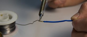
By soldering you can remove a layer of carbon deposits. We make a small bath of solder. You will need a solder rod and flux. Preferably activated (for example, LTI - 120). You can even use regular alcohol rosin. This is in the case of “light” soot, of small size.
Now we divide the solder bar into small pieces and pour a little rosin or flux (even if you have solder containing rosin, this is not enough for this case).
And we begin to bathe the tip in solder. If the solder does not melt, then you need to increase the temperature.
What kind of lighting do you prefer?
Built-in Chandelier
We coat the tip in solder from side to side, without pulling it out, so that the tip is completely enveloped. In a couple of minutes, a small amount of carbon deposits will evaporate, and it will be possible to take a little more fresh solder onto the tip after “bathing”. We leave the soldering iron heated with a drop of water for 10 - 15 minutes.
When doing this work, thoroughly ventilate the room! If the carbon deposits are still difficult to clean off after several attempts, then now you need to use soldering acid. The procedure is the same.
How to fix a wire with a broken clamp
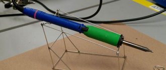
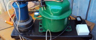
Here's another hint on how to secure the wire in the housing if the fastener is broken. See photo below.
Broken wire clamp.
The idea is as follows: we tighten the plastic clamps tightly on the cable. See photo below.
We cut off the excess so that there are enough protrusions on the wire for fixation.
This way the wire will be firmly fixed in the assembled case, and after assembly, the rest of the part, the one in the form of a spiral, can be fixed to it with electrical tape.
Cable clamp made of clamps
The check showed that everything was fully operational.
Done, you can use it!
I hope this note about repairing a soldering iron for polypropylene pipes will be useful to someone.
Possible causes of failure
Break in the wiring
A power outage is the most common cause of device failure. If the fault is in the electrical cord, then you can correct the situation yourself. It is enough to replace the cord or plug depending on which part of the wiring there is a break.
If the nichrome winding breaks, the repair is carried out in more complex stages, but it is also possible to fix it yourself. To determine whether the winding is broken and repaired, a special device called a multimeter is used. Its use depends on the power, which is indicated on the soldering iron body or in the passport.
The fixing rings are moved apart, and the protective housing of the soldering iron winding is removed. The protection casing is available in two types:
- A metal tube is attached to the winding pin, which rests against the handle and is secured with a clamping ring in the place where the tip is located.
- The protective housing consists of two longitudinal halves of the tube, the edges of which are noticeably reduced in diameter. The two components are secured with clamping rings.
Burnout
The bending area when using a soldering iron is the most vulnerable to parts burning out.
Where the wire enters the soldering iron itself is where repairs need to be done. Having disassembled the tool, you need to ring the wires coming from the plug, and then cut off a small piece (no more than 15 cm) from the entrance to the soldering iron. If there is no contact even with this action, then the piece is cut off from the fork side. In many cases, it is not possible to repair the burnt-out part on your own and restore contact. In this case, you need to replace the wire with a new one, following all the steps described above. If the heating tool itself burns out inside the soldering iron, then this is much more difficult, but it can be eliminated. Repair in one of the following ways:
- Rewind the heating coil if the soldering iron was designed for a power of no more than 36 volts. The supply voltage of 220 volts complicates the task. A thin long wire is wound around the base of the heater. The forks should not have direct contact.
- Replace the entire burnt heating element, which is fixed with one screw, the shortest in length. The tip is fixed with a longer screw.
We suggest watching a video on how to repair a burnt soldering iron:
Bad contacts
In many cases, if there is poor contact, you need to check the voltage supply in the electrical network. If the power of the electric current corresponds to the norm, then the cause of poor contact may be the following:
- Incorrect sting position . It is enough to insert it a little deeper into the body and secure it. If the rod is short, replace it with a suitable one.
- Scale on the tip . Removable with simple sandpaper or a file. The heated tip is dipped in rosin and the tip is rubbed on the braid with solder. When a thin and even layer of solder forms on the tip, the scale has been completely removed.
Winding calculation
Repairing a soldering iron in most cases comes down to a procedure that allows you to rewind a burnt nichrome winding. When replacing it, it is important to correctly select the thickness and diameter of the nichrome wire, as well as the number of turns in the spiral, which determines the generated thermal power.
When calculating and selecting the required wire diameter, we proceed from the resistance value of the soldering iron’s heating winding, which, in turn, is determined by its operating power (supply voltage).
To determine the initial indicator (winding resistance), special tables are used.
| Table for determining the resistance of a nichrome spiral depending on the power and supply voltage of electrical devices, Ohm | ||||||
| Soldering iron power consumption, W | Soldering iron supply voltage, V | |||||
| 12 | 24 | 36 | 127 | 220 | ||
| 12 | 12 | 48,0 | 108 | 1344 | 4033 | |
| 24 | 6,0 | 24,0 | 54 | 672 | 2016 | |
| 36 | 4,0 | 16,0 | 36 | 448 | 1344 | |
| 42 | 3,4 | 13,7 | 31 | 384 | 1152 | |
| 60 | 2,4 | 9,6 | 22 | 269 | 806 | |
| 75 | 1.9 | 7.7 | 17 | 215 | 645 | |
| 100 | 1,4 | 5,7 | 13 | 161 | 484 | |
| 150 | 0,96 | 3,84 | 8,6 | 107 | 332 | |
| 200 | 0,72 | 2,88 | 6,5 | 80,6 | 242 | |
| 300 | 0,48 | 1,92 | 4,3 | 53,8 | 161 | |
| 400 | 0,36 | 1,44 | 3,2 | 40,3 | 121 | |
| 500 | 0,29 | 1,15 | 2,6 | 32,3 | 96,8 | |
| 700 | 0,21 | 0,83 | 1,85 | 23,0 | 69,1 | |
| 900 | 0,16 | 0,64 | 1,44 | 17,9 | 53,8 | |
| 1000 | 0,14 | 0,57 | 1,30 | 16,1 | 48,4 | |
| 1500 | 0,10 | 0,38 | 0,86 | 10,8 | 32,3 | |
| 2000 | 0,07 | 0,29 | 0,65 | 8,06 | 24,2 | |
| 2500 | 0,06 | 0,23 | 0,52 | 6,45 | 19,4 | |
| 3000 | 0,05 | 0,19 | 0,43 | 5,38 | 16,1 | |
Using these tables, you can check the correctness of the winding calculations in order to carry out repairs in the future.
With a fixed supply voltage U and the resistance of the heating device R measured using a tester, the power P consumed by it is calculated using the formula P=(UxU)/R.
What you need to understand
You should be aware that the adapter in question can ensure the operation and full functioning of a device that has a VGA video input only if it can automatically detect the type of incoming video signal. An indicator of this will be the ability to select the mode in which data will be transmitted to RGB/YPbPr. Usage will be positively impacted by sending these types of signals. Why is that?
The fact is that RGB and HV.sync (for example, data coming from the output of a personal computer’s video card) are converted to RGB, which has sync pulses in the green channel (Y). It, in turn, turns into the color-difference YPbPr. And as a result, we can conclude that these signals are not the same thing, although they can convey the same information. Therefore, carefully study what a VGA RCA adapter looks like.
Rules for using power tools
On the shelves of construction stores you can find different models of electric soldering irons that operate on mains power - from 12 to 220 W. The process of choosing a tool should take into account the safety of the working craftsmen and the voltage in the electrical network at the work site.
Attention
In rooms with high humidity, where grounding is provided, it is permissible to use soldering irons with a power of 36 Watt, 25 Watt and lower. In this case, it is necessary to ground the instrument body.
If the instrument is made independently, then a thin wire will be required for its correct reconstruction. It will be wound onto a spiral. The required power is from 12 to 100 W, even more is possible. The material will spread evenly over the surface of the plates if the melting temperature exceeds the temperature in the soldering iron itself.
Buy components for soldering irons
In the catalog of our online store you can choose
An electric soldering iron is a hand-held equipment that allows you to connect parts together using soft solders, heating the solder to a liquid consistency, filling the voids between the elements being connected. Before purchasing a tool, you need to familiarize yourself with the technical characteristics of the device, operating instructions and how to repair a soldering iron.
A soldering iron is a tool necessary for performing minor repairs on electronic devices.
Electrical diagram
To understand the basics of repairing a soldering fixture, it is advisable to familiarize yourself with its diagram, which consists of a number of elements connected in series. It consists of an electrical plug, a connecting wire (cord) and a nichrome heating winding.
Since the power comes from a 220 V AC network, a converter is usually built into the circuit.
Voltage
One of the main technical characteristics taken into account when it is necessary to repair a soldering iron is the voltage supplied to the winding. In different device models, it can take the following values:
- 220 Volt (used in most domestic models);
- supply voltages reduced by a transformer ranging from 12 to 42 Volts (for hazardous working conditions);
- 5-volt power supply for, which is not difficult to repair at home.
Reduced voltages are used in conditions called dangerous and especially dangerous (at high levels of humidity or dust in the room, for example). The main purpose of reducing this value is to protect the user from electric shock.
Regardless of which of these models is subject to repair, the methods for restoring it come down to simple work operations.
Power
Electrical power refers to the energy taken from the network by a soldering iron, defined as the product of voltage and consumed current.
This indicator is directly related to the thermal power dissipated by the tip, which determines its operational capabilities. The higher this parameter, the better the soldering iron tip will warm up the soldering area.
The operating power values for various product samples vary within very wide limits (from units to thousands of watts).
That is, there is a choice when, for working with small parts, preference is given to soldering devices with low consumption and heat dissipation. Well, for cases when you have to solder large metal products, on the contrary, only “powerful” devices are suitable.
Taking this indicator into account in the simplest case comes down to replacing the tip with a thicker tip or vice versa. If the heating element fails, the power is taken into account when it is necessary to rewind it independently and select the required number of turns.
SCART-S-Video wiring
If you really want it, you can buy such a connecting cord or order it online. However, there are cases when such an adapter is easier (or cheaper) to assemble with your own hands. Knowing the pinout of the SCART connector and the pinout of the S-Video connector, it will not be difficult to solder everything yourself. Before creating such a connector, you must first decide from which device the signal will be supplied. In other words, there are two ways to desolder. In the first case, the signal will be taken from the SCART connector and sent to S-Video. In the second case, the signal will be taken from the S-Video connector and sent to SCART. If both options are needed, then it will be easier to solder a universal adapter with two options enabled at the same time. The diagram shown below is not very well drawn from a circuit diagram point of view. However, such a diagram (or rather, a drawing) is more convenient and understandable to a simple user who does not know the symbols of the circuit diagram.
Pinout, where S-Video is the output and SCART is the input. We connect the first S-Video pin to the seventeenth SCART pin. We connect the second S-Video pin to the thirteenth SCART pin. We connect the third S-Video pin to the twentieth SCART pin. We connect the fourth S-Video pin to the fifteenth SCART pin.
Pinout, where SCART is the output and S-Video is the input. We connect the thirteenth SCART pin to the second S-Video pin. The fifteenth SCART pin is connected to the fourth S-Video pin. We connect the seventeenth SCART pin to the first S-Video pin. We connect the nineteenth SCART pin to the third S-Video pin.
As for the audio inputs/outputs, the pinout of these contacts will be similar to that on the SCART-RCA adapter, which was described earlier.
Source: 01010101.ru
Main details
The soldering device is made from a copper rod. A nichrome spiral heats the device. It is important that the heat is immediately transferred from the heating element to the tip - this is the name given to the rod with a wedge-shaped tip. It is inserted into a steel tube, which is wrapped in glassy fabric or mica.
A wire is wound around the mica, which serves as a heating element. To reduce heat loss, nichrome wire is wrapped with asbestos. The ends of the nichrome spiral are connected to the conductors of the electrical cord. To ensure reliability and preservation of the generated heat, the spirals are bent and folded in half at the point of connection with the copper wire. Additionally, they are compressed at the coupling point.
The listed elements are located in a metal case. It can be made in two ways: welded from two parts or constructed from two pieces of metal.
Overlay rings are used to secure the housing to a metal tube . After applying electric current, it is distributed from the nichrome onto the spiral, and after that the heat flows to the tip.
For soldering low-power diodes, experts recommend using an electric current of up to 12 W. Large parts and thick connecting wires need to be soldered with more powerful devices. A soldering iron with a power of 40 to 60 W is suitable. Parts that are complex in design and heat transfer are soldered with devices with a power of 100 W or more.
Fluxes.
Fluxes
designed to dissolve and remove oxides from the surface of soldered parts, serve to protect metal and solder surfaces from oxidation, and ensure good wetting of the surface of parts with liquid solder.
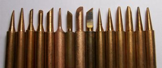
For example, sting
The soldering iron is made of copper, which oxidizes when heated, and a soot crust forms on the working surface of the tip. If you touch the solder with such a tip, it will naturally melt, but it will not remain on the working surface, but will simply roll off, so you will not be able to solder anything with such a soldering iron.
The most common and affordable flux is rosin
, which is made from pine resin. It looks like amber, transparent with a yellowish tint.
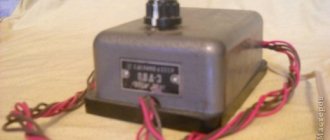
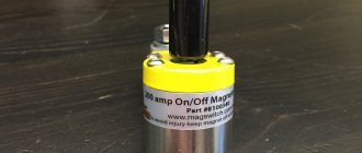
Thermal fuse
And one of the interesting things there is a thermal fuse! This could be the reason for the underheating. It is located under the protective grille, bolted to the heater.
Its function is Additional protection. Although all control - heating, monitoring, turning off and turning on - is taken over by the electronics, the manufacturers have installed additional protection. In case, for example, the thyristor breaks down and the heating element stops being controlled by the controller.
How it works and why it broke
In the event of a breakdown of the electronics, when a certain temperature is reached, the bimetallic contacts of the fuse will open and turn off the heating element, preventing it from overheating. The principle of operation is like an iron, if anyone is familiar with it, they understand what I mean.
A more detailed check showed that this was so, my instinct did not let me down. The reason for this malfunction is as follows. A fairly decent current flows through the closed contacts of this fuse. Under current load, over time, the contacts begin to heat up, then slowly burn - stronger and stronger, and eventually their ability to conduct current becomes worse.
As a result, the amount of energy sufficient for normal heating is not transferred to the heating element. Part of it is lost on these burnt contacts, which makes them heat up even more.
Do you remember what happens when the thermal fuse heats up? As it heats up, its contacts tend to open. All this only further worsens the contact in this circuit or breaks it altogether.
Thermal fuse
What is a VGA RCA adapter
The circuit of this device may seem complicated, but only until you understand it. What is this device? This is an adapter from tulips (RCA connectors) of analog video output to VGA D-Sub for 15 pins. The device reviewed here can be used to connect a DVD player or satellite tuner to a multimedia projector. Of course, provided that it is not possible to work directly using the same type of cable, which is usually common in cheap or outdated devices.
How to fix it?
Which exit? Trying to restore a thermal fuse is a thankless and useless task. Even if this works, it will not last long and soon you will have to disassemble the soldering iron again for repeated repairs.
Replace with a new one? This is ideal! But where can I get one like that? Therefore, the method remains reliable, but radical. Remove him from the chain!
The task is the following. You need to disconnect the fuse terminal (black wire in the photo) from the heating element contact.
Disconnect the terminal
You can, of course, bite off the fuse and connect the blue black wire to the existing terminal, but this is not the best option, since the connection will begin to heat up over time and also needs to be insulated.
But ordinary electrical tape is not suitable for this, because there is strong, natural heating from the heating element, it will melt.
It’s best to crimp a new terminal onto the blue wire; it costs pennies at an electrical goods store. I had the terminals insulated, but I decided to remove it because I’m not sure that it will withstand the temperature. It is better to use the heat-resistant casings that were on the wires.
New terminal
We prepare the wire and crimp the terminal on it; if there are no special pliers for this, this can be done with pliers, the crimping must be reliable, the wire should not dangle in the terminal.
Preparing the wire and terminal for crimping The wire is ready for connection. The wires are connected and ready to be assembled.
Well, the electrical part is ready, all that remains is to put everything together and check it.
Sequence of repair work
To eliminate a break in the wires or plug, first use a multimeter (tester) to identify the exact location of the damage. And only after that one of the possible methods of repairing the soldering iron is selected.
So, if a break is detected in the supply wire or plug, the easiest way is to completely replace these parts with a working product. To do this, it is more convenient to simply extend the undamaged part by soldering a new power cord to it.
When building up the supply wire, special attention is paid to the insulation of individual cores. The most reliable way to protect each of them is with a polyvinyl chloride tube (cambric).
If the soldering iron winding burns out, you will have to open the protective casing (cover) and completely disassemble the heating element, disconnecting it from the power wires.
When rewinding a spiral, you must carefully ensure that adjacent turns are located at a distance from one another, and a mica spacer is placed between the winding rows.
At the end of the winding work, the leads are soldered to the ends of the nichrome wire, and then the supply wires are crimped, after which the protective casing returns to its original place. At this point the repair can be considered complete.