One of the Soviet KT3107 transistors, which, according to its technical characteristics, is a low-power bipolar epitaxial-planar amplification device of a pnp structure, with a normalized noise figure at a frequency of 1 kilohertz. Designed for use in various amplification, switching, generator circuits and other radio equipment for household use.
It gained its popularity in the 1990s, when equipment manufacturers tried to replace the KT361 with the improved KT3107, which differed from the prototype in its higher static current transfer coefficient with a low noise figure at low frequencies. In market conditions, this was necessary for the manufacture of more modern domestic audio equipment and to withstand competition with imported products. Due to the subsequent transition to microchips, it did not become as popular as its prototype.
Pinout
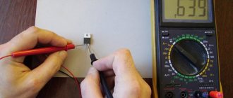
Unlike its complementary pair, this transistor is produced exclusively in a plastic housing KT-26 (TO-92) and has flexible leads of different lengths. If the KT3107 is new, then the pinout is easily determined by the pins. The longest pin is the “emitter”, and the shortest is the “collector”. The output base is in the middle.
Due to the design reduced thickness of the base, it has an increased current gain and is classified as a “subeta transistor”.
Some manufacturers allow no protrusions on the terminals. Maximum positional tolerance up to 2 mm. Below is a dimensional drawing of the KT-26 (TO-92) housings, characteristic of the device in question.
Analogues of transistor KT3102
KT3102A
: 2N4123, BC547A, BC548A, BCY59-VII, BCY65-VII, BC107AP, BC182A, BC183A, BC237A, BC317, BC238A, MPS3709 KT3102B
:
2N2483, 2SC538A, 2SC828A, BC 452, BC547B, BCY56, BCY59-VIII, BCY59-IX, BCY65-VIII, BCY65-IX, BCY79, MPSA09, 2SC1000GTM, 2SC1815, BC182B, BC182C, BC183B, BC237B, BC318, BC382B, SF132E, BC183C, PN2484 KT3102V: 2SC828, BC548B, MPS3708, MPS3710, 2N3711, 2SC454B, 2SC454C
,
2SC454D , 2SC458, 2SC458KB, 2SC458KC, 2SC458KD, BC108AP, BC238B, BC451, SF131E
KT3102G
: 2SC538, 2SC900, 2SC923, BC547C, BC548C, MPS3711, MPS6571, BC108 CP, BC238C, BC382C, SF131F, SF132F
KT3102D
: 2N2484, 2N5209, 2SC945, BC453 , BC521, BC521C, BC549A, BC549B, BCY59-x, MPS3707, MPS6512, MPS6513, MPS6514, MPS6515, 2N4124, 2SC458LGB, 2SC458LGC, 2SC458LGD, BC109BP, BC184A, BC 239B, BC383B, BC384B KT3102E: 2N5210, BC549C, BCY57,
BC109CP
, BC184B, BC239C, BC319, BC383C, BC384C, BFх65
Characteristic
The KT3107 series of transistors is divided into several groups, slightly different in their technical parameters. Mainly by saturation voltage, static current gain. The noise figure may also vary between models. Therefore, when choosing, pay attention to the last letter in its marking, it indicates the group. Below are the parameters typical for transistors of the KT3107 series of all groups:
physical:
- operating principle – bipolar;
- body: plastic for KT-26 (foreign TO-92);
- crystal material – silicon (Si);
- PNP structure (direct conduction);
- weight – no more than 0.3 g (g);
- technical specifications: aA0.336.170 TU/04.
basic electrical values:
- ICBO (ICBO) no more than 100 nA (nA), if UKB max. (VCB max) = 20 V (V) and IE (IE) = 0;
- IEBO (IEBO) no more than 100 µA (µA), if UEB max. (VEB max) = 5 V (V) and IC (IC) = 0;
- fgr normal (ftTYP) not less than 250 MHz (MHz), if UCB (VCB) = 5 V (V), IC (IC) = 10 mA (mA);
- SK (SS) 7.0 pF (pF) at UKB (VCB) = 10 V (V), IE (IE) = 0, f = 10 MHz (MHz);
- CN (Noise Figure) NF within 4 -10 dB (dB), if UCE (VCE) = 3 V (V), IK (Ic) = 0.2 mA (mA);
- h21e in the range from 70 to 800, with UKE (VCE) = 5 V (V), IK (Ic) = 2 mA (mA);
- Tokr. from -40 to +85 °C;
Limit values for electrical operating conditions (at Tam. = +25 °C):
- U KB max. (V CBmax) from 25 to 50 V (V);
- U CE max. (VCEmax) from 20 to 45 V (V);
- U EB max. (V EB max) up to 5 V (V);
- IK MAX (IC MAX) 100 mA (mA);
- PK max. (PC) 300 mW (mW);
- Ttransition (Tj) up to + 150 °C
When the temperature rises above +25 °C, the permissible maximum power dissipation can be determined as follows: PK max = (150 - Tamb. °C) / 0.4 °C, mW.
Specifications
Now let's look at the technical characteristics of transistors of the KT3102 series. Let's start with the maximum permissible ones, as critically important. They were measured at a standard temperature of 25°C:
- potential difference K-B:
- KT3102A, KT3102B – 50 V;
- KT3102V, KT3102D – 30 V
- potential difference K-E:
- KT3102A, KT3102B – 50 V;
- KT3102V, KT3102D – 30 V
- potential difference E-B – 5 V;
- collector current – 100 mA;
- short-term current through the collector (pulse time no more than 40 μs) – 200 mA;
- power – 250 mW;
- temperature at which the transistor can function normally from -40 to +85 °C.
After the limits, we will also get acquainted with the electrical parameters. They are important because the capabilities of the KT3102 depend on them. Measured at the same standard temperature, and the remaining test conditions are given in a separate column in the table.
| Electrical characteristics of the KT3102 transistor (at T = +25 o C) | ||||||
| Options | Test Modes | Tr-r | min | typ | max | Unit change |
| Static gain in the OE circuit | UCB = 5 V, IE = 2 mA, T = +25°C | KT3102A | 100 | 250 | ||
| KT3102B, V, D | 200 | 500 | ||||
| UCB = 5 V, IE = 2 mA, T = -40°C | KT3102A | 25 | 250 | |||
| KT3102B, V, D | 50 | 500 | ||||
| UKB = 5 V, IE = 2 mA, T = +85°C | KT3102A | 100 | ||||
| KT3102B, V, D | 200 | |||||
| Cutoff frequency | UKB = 5 V, IE = 10 mA | ALL | 300 | MHz | ||
| Noise level | UKB = 5 V, IE = 0.2 mA F = 1 kHz, RG = 2 kOhm | KT3102A, B, V | 5 | 10 | dB | |
| KT3102D | 2,5 | 4 | ||||
| Boundary potential difference | IB = 0 V, IE = 10 mA | KT3102A, B | 30 | IN | ||
| KT3102V, D | 20 | |||||
| Reverse current K-E | UKE = 50 V | KT3102A, B | 0,1 | µA | ||
| UKE = 30 V | KT3102V, D | 0,05 | ||||
| Reverse current through K | T = +25°С | KT3102A, B | 0,1 | µA | ||
| T = -40°С | 0,05 | |||||
| T = +85°С | 5 | |||||
| T = +25°С | KT3102V, D | 0,05 | ||||
| T = -40°С | 0,015 | |||||
| T = +85°С | 5 | |||||
| Reverse current through E | UEB = 5 V | ALL | 10 | µA | ||
| Capacity on the collector | UKB = 5 V | ALL | 6 | pF | ||
Marking
The first Soviet transistors of the KT3107 series appeared in 1977 and they had color markings consisting of four colored dots. Subsequently, from 1986, code marking was used.
Color
A light blue dot will be applied to the beveled part of the body in the upper left corner. The color of the dot to the right determines group affiliation: pink – “a”; yellow – “b”; blue – “in”; beige – “g”; orange – “d”; electrician – “e”; salad - “f”; green – “and”; red – “k”; gray – “l”. At the bottom, color dots indicated the release date: month and year. An example of color coding for a KT3107A transistor produced in 1977.
Code
Letters and figures, according to standard code markings, are printed in white. KT3107 is indicated by a white isosceles triangle, on the beveled side of the case, top left. To the right of the figure the group is indicated by a letter. At the bottom is the year of manufacture and month, respectively. The month and year are indicated by a number or a Latin letter.
Non-standard
There are also non-standard color and code markings. With a code there are no special rules. You just need to remember what the transistor looks like in such cases.
Currently, manufacturers indicate on the case the full name of the model and the date of manufacture in accordance with GOST 25486-82 and TU bKO.347.098 TU1.
To determine the version of transistors from the information on the case, many radio amateurs use the Color and Code 9.3 program.
Characteristics of transistor KT3102
KT3102 – silicon bipolar transistors npn low power high frequency.
Foreign analogue of KT3102
- Can be replaced with BC547
Peculiarities
- Complementary pair – KT3107
Case version
- metal-glass case
Pinout KT3102 (metal-glass case)
No. 1 - Emitter
No. 2 - Base
No. 3 - Collector
Characteristics of transistor KT3102
Limit parameters kt3102
Maximum permissible direct collector current (IC max):
- KT3102G - 100 mA
- KT3102V - 100 mA
- KT3102D - 100 mA
- KT3102A - 100 mA
- KT3102B - 100 mA
- KT3102E - 100 mA
Maximum permissible collector pulse current (IC, and max):
- KT3102G - 200 mA
- KT3102V - 200 mA
- KT3102D - 200 mA
- KT3102A - 200 mA
- KT3102B - 200 mA
- KT3102E - 200 mA
The maximum permissible constant collector-emitter voltage with a base current equal to zero (UKE0 max) at T = 25° C:
- KT3102V - 30 V
- KT3102D - 30 V
- KT3102A - 50 V
- KT3102B - 50 V
- KT3102E - 50 V
The maximum permissible DC voltage collector-emitter with resistance in the base-emitter circuit (UKER max) at T = 25 ° C:
- KT3102g - 20 V
The maximum permissible constant collector-base voltage with an emitter current equal to zero (UKB0 max) at T = 25° C:
- KT3102G - 20 V
- KT3102V - 30 V
- KT3102D - 30 V
- KT3102A - 50 V
- KT3102B - 50 V
- KT3102E - 50 V
The maximum permissible constant emitter-base voltage with a collector current equal to zero (UEB0 max) at T = 25° C:
- KT3102G - 5 V
- KT3102V - 5 V
- KT3102D - 5 V
- KT3102A - 5 V
- KT3102B - 5 V
- KT3102E - 5 V
Maximum permissible constant power dissipation of transistors (Pmax) at T = 25° C:
- KT3102G - 250 mW
- KT3102V - 250 mW
- KT3102D - 250 mW
- KT3102A - 250 mW
- KT3102B - 250 mW
- KT3102E - 250 mW
Maximum permissible junction temperature (Tп max):
- KT3102G - 125 ° C
- KT3102V - 125 ° C
- KT3102D - 125 ° C
- KT3102A - 125 ° C
- KT3102B - 125 ° C
- KT3102E - 125 ° C
Maximum permissible ambient temperature (Tmax):
- KT3102G - 85 ° C
- KT3102V - 85 ° C
- KT3102D - 85 ° C
- KT3102A - 85 ° C
- KT3102B - 85 ° C
- KT3102E - 85 ° C
Electrical characteristics of KT3102 transistors at T = 25oC
Static current transfer coefficient of a bipolar transistor (h21E) at a constant collector-base voltage (UCB) of 5 V, at a constant emitter current (IE) 2 mA:
- KT3102G — 400 — 1000
- KT3102V — 200 — 500
- KT3102D — 200 — 500
- KT3102A — 100 — 250
- KT3102B — 200 — 500
- KT3102E — 400 — 1000
Reverse collector current (IKB0)
- KT3102G - 0.015 µA
- KT3102V - 0.015 µA
- KT3102D - 0.015 µA
- KT3102A - 0.05 µA
- KT3102B - 0.05 µA
- KT3102E - 0.015 µA
Bipolar Transistor Noise Figure (Ksh)
- KT3102G - 10 dB
- KT3102V - 10 dB
- KT3102D - 4 dB
- KT3102A - 10 dB
- KT3102B - 10 dB
- KT3102E - 4 dB
Collector junction capacitance (CC)
- KT3102G - 6 pF
- KT3102V - 6 pF
- KT3102D - 6 pF
- KT3102A - 6 pF
- KT3102B - 6 pF
- KT3102E - 6 pF
Thermal resistance of junction-medium (RT p-s)
- KT3102G - 400 ° C/W
- KT3102V - 400 ° C/W
- KT3102D - 400 ° C/W
- KT3102A - 400 ° C/W
- KT3102B – 400 ° C/W
- KT3102E - 400 ° C/W
Published 01/24/2020
| Microcircuits | Transistors | Diodes | Thyristors |
DC-DC buck converter - product link.
Application
Most often, during the Soviet period, KT3107 was used in products for playing records and various sound amplifiers together with KT3102. This pair can now be found in various popular amateur radio circuits: microphone amplifier, radio microphone, headphone amplifier, etc. KT3107 is used not only in signal amplification devices and signal generator circuits. Due to the fact that they can operate in saturation and cutoff modes, they are used as electronic keys. For an example of using the device in this mode, watch the video.
Analogs
Analogues for any KT3102 series must be selected depending on the specific device, because they have different letter indices and differ in parameters. Therefore, we present a possible replacement in the form of a table, in which the name of one of the transistors will be located on the left, and its prototype on the right.
| Transistor | Analogue |
| KT3102 | BC174, BC182 |
| KT3102A | 2SC945, BC107AP, BC182A, BC237, BC547A, BC548A, BC550A, KT6111A |
| KT3102AM | BC547A |
| KT3102B | BCY79, BC547C, 2N5210, 2SC945G, BC182B, BC107BP, BC546B, BC550B, BC237B, KT6111B, BC183B, BC183C, BC337, BC547B, 2SC1815, 2N2483 |
| KT3102BM | BC547B |
| KT3102V | 2N3711, 2SC458, 2SC828, BC108, BC548, BC549, KT373V |
| KT3102VM | BC548B |
| KT3102G | 2SC538, BC547C, BC548C, |
| KT3102D | 2N2484, 2N4124, 2N5209, 2SC945, BC109, BC521, BC549A, BC549B, MPS6515 |