Neodymium magnet is a rare earth metal that is resistant to demagnetization and has the ability to magnetize certain materials. Used in the manufacture of electronic devices (computer hard drives, metal detectors, etc.), medicine and energy.
Neodymium magnets are used in the manufacture of generators operating in various types of installations that generate electric current.
Currently, generators made using neodymium magnets are widely used in the manufacture of wind turbines.
Homemade windmill
Purchasing a wind generator is an expensive and not always completely effective undertaking.
Samples of commercially available wind turbines have a limited service life, low maintainability and high price. Purchasing such a kit is beyond the means of many potential users. The way out is to manufacture a wind generator yourself, which costs much less and allows you to get a device with high efficiency and productivity. A homemade windmill has high maintainability and, as a result, a long service life. Often, during operation, the design is modernized, improved and brought to the highest possible parameters, which cannot be done with factory kits.
Advantages
Devices can be purchased ready-made or made independently. Having purchased a wind generator, all that remains is to install it. All adjustments and alignments have already been completed, tests have been carried out under various climatic conditions.
Neodymium magnets, which are used instead of a gearbox and bearings, allow you to achieve the following results:
- friction is reduced and the service life of all parts is increased;
- vibration and noise of the device during operation disappears;
- the cost decreases;
- energy is saved;
- There is no need to regularly service the device.
A wind generator can be purchased with a built-in inverter that charges the battery, as well as a controller.
Low-speed wind generators
The most attractive wind turbine designs for most regions of Russia are those that give high performance in weak and medium winds - low-speed wind turbines. They are characterized by the ability to start rotating at low flow rates, producing sufficient voltage to power consumer devices.
Energy generation in such devices is carried out by generators adapted to work with wind turbines. The design specificity of such generators is high sensitivity, since the device is initially designed to operate at low rotation speeds.
In order to ensure the specified operating mode, it is necessary to exclude the excitation winding from the design, replacing it with permanent magnets. As a result, there will be no need to supply voltage to form electromagnets, and induction will become more stable, independent of the power source on the rotor winding. In addition, there will be no need for a brush assembly that supplies power to the field winding.
Electrical and technical parameters of the generator
The voltage is calculated using the formula:
Homemade generator
U=2*Ch*KP*KK*KV*MI*P, where:
- U – voltage in Volts;
- H – frequency of rotation of the generator rotor per second;
- KP – number of magnetic poles;
- КК – number of induction coils in the stator;
- KV – the number of turns of the conductor in one induction coil;
- MI is the magnetic induction in T, which is formed in a standard gap (2 mm);
- P – surface area of one neodymium magnet, in sq. m.
If simple coils are used, a magnetic induction of 0.5 Tesla is taken for calculation. When adding an electrical steel core, the value is increased to 0.7-0.9 T.
For your information. The formula is valid when connecting the windings in a triangle. If a three-phase generator is assembled using a star circuit, the resulting value is multiplied by a correction factor of 1.7.
After calculating the voltage, you need to find out the resistance in the windings. After this, it will be easy to determine the current and power. For a copper conductor, the resistivity is 0.0175 Ohm per mm2/meter. To calculate the total value, use the formula:
C= (US*D)/PP, where:
- C – resistance, in Ohm;
- US – resistivity of a certain material;
- D – conductor length in meters;
- PP – conductor cross-sectional area, mm sq.
To calculate the current, subtract the voltage of the battery connected for charging from the voltage of the magnetic generator at idle. The resulting value is divided by the resistance value calculated using the previous formula.
Increasing/decreasing the speed changes the current accordingly while keeping the voltage at the battery terminals constant. To calculate the performance of a wind turbine in different modes, use the standard formula:
P=I*U, where:
- P – power, Watt;
- I – current strength, Ampere;
- U – voltage, Volt.
Manufacturing a permanent magnet rotor
The design of a permanent magnet generator is in some ways simpler than that with electromagnetic excitation. The creation of such a device can be carried out either on the basis of a ready-made generator or using improvised materials.
Modification of a car generator
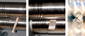
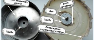
Creating a permanent magnet rotor requires quite a serious intervention in the design. It is necessary to reduce the diameter by the thickness of the magnets plus the thickness of the steel sleeve, which is placed on the rotor to form a continuous magnetic flux and at the same time serves as a landing pad for the magnets. Some experts do without a sleeve, installing magnets directly on the rotor with a reduced diameter and fixing them with epoxy.
The manufacturing process requires the participation of production equipment. The rotor is clamped into the lathe and the layer is carefully removed so that the installed magnets rotate with minimal clearance, but quite freely. The magnets are installed on the rotor plates with alternating polarity.
The greatest effect can be achieved when installing relatively small-sized magnets arranged in rows in the longitudinal direction. A smooth and powerful magnetic flux is achieved, acting on the stator power windings with uniform density at all points.
Making a rotor from a hub and brake disc
The considered method applies to ready-made generators that require minor design changes. Such devices include car generators, which are often used by amateur designers as a basic device. Often, generators are assembled completely independently, without having a ready-made device.
In such cases, they act somewhat differently. The basis is a car hub with a brake disc. It is well-balanced, durable and adapted to certain types of loads. In addition, the size of the hub allows a large number of magnets to be placed around the circumference, allowing three-phase voltage to be obtained.
Magnets with alternating polarity are placed at a distance equidistant from the center. Obviously, the highest number can be set by gluing them as close to the outer edge as possible. The most accurate indicator will be the size of the magnets, which will determine the possibility of placement at a certain distance. The number of magnets must be even so that the rhythm of alternating poles during rotation does not break down.
Gluing magnets to the hub is done using any glue; the best option is epoxy resin, which is used to completely fill the magnets. This protects them from moisture or mechanical stress. Before pouring, it is recommended to make a plasticine rim along the edge of the hub to prevent the epoxy from flowing down from the hub.
The design of the generator on a car hub is most convenient when making a vertical windmill. It is noteworthy that a similar scheme can be used without a hub, on a disk cut from ordinary plywood. This design is much lighter, allows you to choose a convenient size, which makes it possible to create a sensitive and productive device.
How to make a perpetual motion machine
Homemade generators with neodymium magnets are basically the same type in terms of their operating principle. The standard option is the axial type.
It is based on a car hub with brake discs. Such a base will become reliable and powerful.
When deciding to use it, the hub should be completely disassembled and checked to see if there is enough lubrication, and if necessary, clean off the rust. Then the finished device will be pleasant to paint, and it will take on a “homey”, well-groomed appearance.
Magnets are glued to the rotor discs. The author of the design presented in the photo in the article took twenty pieces measuring 25*8 millimeters. A different number of poles can be used.
In a single-phase device, the number of poles must be equal to the number of magnets. In three-phase, the ratio of two to three or four to three must be observed. Magnets are placed with alternating poles. They must be precisely located. To do this, you can draw a template on paper, cut it out and accurately transfer it to the disk.
To avoid mixing up the poles, make notes with a marker. To do this, magnets are brought on one side: the one that attracts is designated with a “+” sign, and the one that repels is marked with a “-”. Magnets must attract, that is, those located opposite each other must have different poles.
Usually superglue or something similar is used, and after sticking it is filled with more epoxy resin to increase strength, after making “borders” so that it does not leak out.
Windmill with axial generator on neodymium magnets
The strongest magnets with optimal parameters for use in generator design are neodymium magnets . They are somewhat more expensive than conventional ones, but they are many times superior and make it possible to create a powerful device in a relatively compact size.
There is no fundamental difference in the design. Neodymium magnets are manufactured in various form factors, allowing you to choose the most convenient option for yourself - thin oblong bars, tablet shape, cylinders, etc. if a metal rotor is used, then it is not necessary to glue the magnets; they themselves are attached to the base with force. All that remains is to fill them with epoxy to protect them from corrosion.
The easiest way to purchase such magnets is through the Internet; at the same time, you can immediately choose the most convenient shape.
Advantages and disadvantages
The advantages of wind generators made using neodymium magnets include the following characteristics:
High efficiency of devices, achieved by minimizing friction losses;
- Long service life;
- No noise or vibration during operation;
- Reduced costs for installation and installation of equipment;
- Autonomy of operation, allowing operation without constant maintenance of the installation;
- Possibility of self-production.
The disadvantages of such devices include:
- Relatively high cost;
- Fragility. Under strong external influence (impact), a neodymium magnet can lose its properties;
- Low corrosion resistance, requiring special coating of neodymium magnets;
- Dependence on operating temperature – when exposed to high temperatures, neodymium magnets lose their properties.
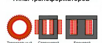
Stator manufacturing
The stator is the stationary part of the generator that carries the power winding that induces electric current. Depending on the type of design, the stator can be used from a ready-made device (for example, from a car generator), or made from scratch yourself. The manufacturing technique is different in each case, but the principle remains general - coils that generate alternating current are located along the circle surrounding the rotating rotor.
When modifying a car generator, sometimes the power windings are not touched, preferring to change the rotor design and leave it at that. Most often, the reason for this is poor technical or theoretical training, when the master has a very vague idea of how exactly such things are done. Let's take a closer look at the question:
Selecting the number of phases
Many craftsmen try to make their task easier by making a single-phase generator. In this case, the simplicity is very questionable, since savings in effort are achieved only at the stage of winding the coils. But during operation, an unpleasant effect is obtained - the voltage amplitude has a classic appearance, which is why the rectified current has a pulsating structure.
Jumps are contraindicated for batteries; they create a negative impact on all components of the complex and contribute to rapid failure. Vibration appears, which can cause complaints from neighbors or cause discomfort for people or animals.
The three-phase design, on the contrary, has a softer envelope; in the rectified state, the current has practically no deviations. The power of the device is stable, the mechanical and electrical parts of the unit are kept in working order.
The choice between a three- and single-phase device should definitely be made in the direction of a three-phase design. The number of wound coils increases, but the number of turns is not so large as to give up a better result due to illusory time savings.
Autogenerator stator modification
A car generator has ready-made power coils tightly packed in the stator channels. To obtain a high-quality result, it is necessary to change the sensitivity of the stator, since the nominal speed of a car engine is in the range of 2000-3000 rpm, and at its peak it can rise to 5000-6000 rpm. A windmill is not able to produce such parameters, and the use of an overdrive gear will significantly reduce the power of the impeller.
The solution to the problem is to increase the number of turns, for which the old windings are dismantled and new ones are wound in their place, with a larger number of turns from thinner wire. At the same time, you cannot use too thin a wire, since as the number of turns increases, the resistance also increases, making the generator less productive. It is necessary to observe the “golden mean”, increasing the amount carefully, without excessive zeal.
Important! Such an operation requires calculation, but in practice it is most often done simply - they wind as many turns as the stator structure can accommodate. The result is usually positive, since it will not be possible to accommodate too many turns.
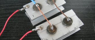
Manufacturing of axial type stator
This design is suitable for an axial type generator, the rotor of which is created from a hub and a brake disc from a car wheel. The stator has the shape of a flat disk, around the circumference of which the power windings are located. They must be wound from thick enough wire so that the number of turns is sufficient, but the resistance does not reduce the efficiency of the design. The number of coils is a multiple of three, so that each phase has the same number.
They are connected to each other by a star, for each phase 1, 4, 7, 10, etc. are connected. When winding a single-phase stator, each coil is wound in the opposite direction - the first clockwise, the second counterclockwise, then clockwise again, etc. they are connected in series.
The finished stator is installed coaxially with the rotor. The gap between the coils and neodymium magnets should be minimal, but the rotor moves freely, without contact with the coils.
To protect against moisture, dust or other influences, the coils are usually filled with epoxy resin. To do this, a plasticine rim with a height slightly higher than the fill layer is first made along the outer edge of the stator disk.
Alternating single-phase and three-phase electric current
Electric current is the directed movement of electrically charged particles under the influence of an electric field (Appendix, Fig. 1). Such particles can be: in conductors - electrons, in electrolytes - ions (cations and anions). In the theory of electrical circuits, current is considered to be the directional movement of charge carriers in a conducting medium under the influence of an electric field. Conduction current is the amount of electricity flowing per unit time through the cross section of a conductor:
i=q/t,
where i is current (A), q = 1.6·109 is electron charge (C), t is time (s).
But this expression is valid only for DC circuits. For alternating current circuits, the so-called instantaneous current value is used, equal to the rate of change of charge over time:
i(t)= dq/dt.
An electric current is called alternating if it changes its direction over a certain time and continuously changes in magnitude. The value of alternating current varies according to a sinusoidal law (Appendix, Fig. 2):
i = Im sin (2πft),
Where; i – instantaneous current value, Im – amplitude or maximum current value, f – alternating current frequency value, t – time.
Alternating current is widely used due to the fact that alternating current electricity can be technically simply and economically converted from lower voltage energy to higher voltage energy and vice versa. This property of alternating current allows electricity to be transmitted through wires over long distances.
Industrial alternating electric current is obtained using electric generators, the operating principle of which is based on the law of electromagnetic induction. The rotation of the generator is carried out by some energy source.
Alternating single-phase electric current has the following main characteristics:
f – frequency of alternating current determines the number of cycles or periods per unit of time. The unit of measurement of alternating current frequency is Hertz (Hz) (1Hz = 10-3kHz = 10-6mHz);
Τ – period – time of one complete change of a variable value (if 1 period Τ occurs in 1 second, then frequency f = 1 Hz);
ω – angular velocity equal to – ω=2πf;
The current strength at individual moments when it changes along a sinusoid is called instantaneous current values. The largest instantaneous value of a single-phase alternating current when it changes along a sinusoid is called amplitude. Currently, the three-phase alternating current system is most widespread throughout the world. A three-phase system of electrical circuits is a system consisting of three circuits in which alternating electromotive forces of the same frequency act, shifted in phase relative to each other by 1/3 of the period (φ = 2π/3) (Appendix, Fig. 3) . Each individual circuit of such a system is briefly called its phase, and the system of three phase-shifted alternating currents in such circuits is simply called three-phase current.
Impeller assembly
The impeller should provide maximum sensitivity. Before you start building a wind turbine, you should study in detail the meteorological situation in the region, the direction and speed of the prevailing winds, the frequency and strength of squalls, and the possibility of hurricanes. This information will help you choose the most suitable windmill design (vertical or horizontal, size, number of blades, etc.).
The impeller is created from available material based on the parameters of the generator. The size of the blades should allow rotation to begin at low flow rates, but not create an excessively large obstruction. This will reduce the risk of the mast falling during a strong gust or squall.
Regions with unstable and frequently changing winds (which are the majority in Russia) are more suitable for the operation of vertical structures. Horizontal wind turbines are considered more efficient, but require installation on tall masts, which creates maintenance problems.
The wind generator impeller must be well balanced and firmly connected. Installing the kit on the roof of a house is prohibited, especially if several families live in it. It is recommended to choose an open, elevated location near your home so that the length of the cable does not create much resistance. There should be no obstacles, tall trees or buildings nearby that would block the direct flow of wind.
How the devices work
The main problem of the design was considered to be the return of rotating parts to their original position without significant loss of torque. This problem was solved by using a copper conductor through which an electric current was passed, causing attraction. When the current was turned off, the attraction stopped. Thus, devices of this type used periodic on-off switching.
The increased current creates an increased attractive force, which, in turn, is involved in the generation of current passing through the copper conductor. As a result of cyclic actions, the device, in addition to performing mechanical work, begins to produce electric current, that is, perform the functions of a generator.
Source of electricity
Tariffs for electricity services increase at least once a year, often several times. This hits the pockets of citizens whose wages are not growing as rapidly. Home craftsmen used to resort to a simple, but rather unsafe and illegal way to save on electricity. They attached a neodymium magnet to the surface of the flow meter, after which it suspended the operation of the meter.
If this scheme initially worked smoothly, then later problems arose with it. This was explained by several reasons:
- Inspectors began to visit homes more often and conduct unscheduled inspections.
- Special stickers began to be glued to the meters, under the influence of which the magnetic fields began to darken. Accordingly, identifying such an intruder was not a problem.
- New meters began to be produced that were not susceptible to magnetic fields. Instead of standard models, electronic units appeared.
All this pushed people to search for alternative sources of electricity, for example, wind generators. If a person lives in areas where winds regularly blow, such devices become a “lifesaver” for him. The device uses wind power to generate energy.
The body is equipped with blades that drive the rotors. The electricity obtained in this way is transformed into direct current. In the future, it passes to consumers or accumulates in the battery.
A homemade wind generator can act as the main or additional source of energy. As an auxiliary device, it can heat water in a boiler or power household lamps, while all other electronics operate from the main network. It is also possible to operate such generators as the main source where houses are not connected to electricity. Here the devices are powered:
- lamps and chandeliers;
- heating equipment;
- consumer electronics.
A wind power plant is capable of powering low-voltage and classical appliances. The first ones operate on a voltage of 12-24 Volts, and the wind generator is capable of providing power at 220 Volts. It is manufactured according to a circuit using inverter converters. Electricity is stored in its battery. There are modifications for 12-36 Volts. They have a simpler design. They use standard battery charge controllers. To ensure heating of your home, it is enough to make wind generators with your own hands at 220 V. 4 kW is the power that their engine will provide.
Legality of installation
It is not prohibited to install installations with an output power of up to 75 kW on your own territory, and no approvals will be required (a fact enshrined in the Resolution of the Russian Cabinet of Ministers).
And if you need to install a powerful generator of an industrial or commercial type, then you will need special preparation related to the creation of the foundation and fencing of the site - and this is already considered capital construction.
It is recommended that you read local regulations regarding energy and utility services before installing VEL. Different regions may have their own rules.
It is important! Products with power up to a kilowatt are considered as household electrical products and do not require certification or any restrictions on use.
Generator selection
Making your own generator will require skills that not everyone has. For example, performing turning work. Therefore, it is necessary to consider the problem of purchasing a factory device that could be used on a wind turbine.
Types and features:
- Alternating current generators (asynchronous) are very easy to find and adapt to a wind generator. Cons: insufficient power; the unit will require modifications during installation.
- DC generators work great at low speeds and require almost no modifications. Disadvantages - it is difficult to find high-power generators.
- Asynchronous - it’s not a problem to buy a generator for little money, but such units are ineffective at high shaft rotation speeds, and internal resistance limits their power.
Generators are divided into two types according to the number of phases at the output. Single-phase generators are simple in design, but under high loads they vibrate strongly and can hum. Three-phase devices do not have these disadvantages, and in some modes they operate more efficiently.
Features of mast installation
Most often, the mast is made from metal blanks - either in the form of a complex frame (for large and powerful installations), or using one pipe (round/square cross-section), which is dug into the ground. In both cases, it is recommended to strengthen the mast with 3-4 guys made of metal rope.
Connection process in the house
After installing an almost silent windmill with good power, you need to connect household appliances to it. When assembling such a device with your own hands, you should take care of purchasing an inverter converter with an efficiency of 99%. In this case, the losses due to the transition of direct current to alternating current will be the smallest, and there will be three nodes in the housing:
- Battery pack. Capable of storing energy generated by the device for future use.
- Charge controller. Provides longer battery life.
- Converter. Transforms direct current into alternating current.
You can install equipment to power lighting fixtures and household appliances that can operate on a voltage of 12-24 Volts. In this case, there is no need for an inverter converter. For appliances that allow you to cook food, it is better to use gas equipment powered by a cylinder.
Conclusions and additional information
Using a gearbox and careful calculation of the blades, you can create a low-speed, low-noise, low-speed generator using neodymium magnets. Modern electronic components and corresponding circuitry will help create an inverter with high efficiency. New battery models perform their functions flawlessly, without routine maintenance, and retain their useful functions after hundreds of recharge cycles.
Wind generators with a vertical axis of rotor rotation
To get acquainted with existing installations, you can see the implemented projects of Sergei Savchenko, Alexander Sedov, Valery Yalovenko, Victor Burlak. Their ideas can be transformed taking into account personal capabilities and preferences. It’s easy to simplify calculations using specialized calculator programs that can be quickly found on the Internet. In any case, the magnetic generator should be considered in conjunction with other parts of the off-grid power supply system to ensure good coordination.
Phases - which is better - three or one?
Many lovers of electrical equipment follow the path of least resistance and, in order not to bother, opt for a single-phase stator for a windmill. However, it has one unpleasant feature that neutralizes the ease of assembly - vibration when loaded, due to the variability of current output. After all, the amplitude of such a stator is abrupt, reaching a maximum when neodymium magnets are located above the coils, and then dropping to a minimum.
But when the generator is made using a three-phase system, there are no vibrations, and the power indicator of the windmill has a constant value. The reason for this difference is that the current, falling in one phase, at the same time increases in the other. As a result, a wind generator operating in a three-phase system can be up to 50% more efficient than the exact same one using a single-phase system. And most importantly, a loaded three-phase generator does not produce vibration, therefore, the mast does not give rise to complaints about the wind generator to the supervisory authorities from ill-wishers among neighbors, since it does not create an annoying hum.
Conclusions and additional information
Using a gearbox and careful calculation of the blades, you can create a low-speed, low-noise, low-speed generator using neodymium magnets. Modern electronic components and corresponding circuitry will help create an inverter with high efficiency. New battery models perform their functions flawlessly, without routine maintenance, and retain their useful functions after hundreds of recharge cycles.
To get acquainted with existing installations, you can see the implemented projects of Sergei Savchenko, Alexander Sedov, Valery Yalovenko, Victor Burlak. Their ideas can be transformed taking into account personal capabilities and preferences. It’s easy to simplify calculations using specialized calculator programs that can be quickly found on the Internet. In any case, the magnetic generator should be considered in conjunction with other parts of the off-grid power supply system to ensure good coordination.
The nature of magnetism
The demonstration of the properties of a magnet in attracting metal objects to itself raises the question among people: what are permanent magnets? What is the nature of such a phenomenon as the occurrence of traction of metal objects towards magnetite?
The first explanation of the nature of magnetism was given in his hypothesis by the great scientist Ampere. Electric currents of varying degrees of strength flow in any matter. Otherwise they are called Ampere currents. Electrons, rotating around their own axis, also revolve around the nucleus of the atom. Thanks to this, elementary magnetic fields arise, which, interacting with each other, form the general field of matter.
In potential magnetites, in the absence of external influence, the fields of the atomic lattice elements are randomly oriented. An external magnetic field “arranges” the microfields of the material structure in a strictly defined direction. The potentials of opposite ends of magnetite repel each other. If you bring the identical poles of two strip PMs closer, then a person’s hands will feel resistance to movement. Different poles will tend to each other.
When steel or an iron alloy is placed in an external magnetic field, the internal fields of the metal are strictly oriented in one direction. As a result, the material acquires the properties of a permanent magnet (PM).
Main characteristics
In order to determine the feasibility of manufacturing a generator using neodymium magnets, you need to consider the main characteristics of this material, which are:
- Magnetic induction B is a strength characteristic of a magnetic field, measured in Tesla.
- Residual magnetic induction Br is the magnetization possessed by a magnetic material when the external magnetic field strength is zero, measured in Tesla.
- Coercive magnetic force Hc - determines the resistance of a magnet to demagnetization, measured in Amperes/meter.
- Magnetic energy (BH)max - characterizes how strong the magnet is.
- Temperature coefficient of residual magnetic induction Tc of Br – determines the dependence of magnetic induction on the ambient temperature, measured as a percentage per degree Celsius.
- Maximum operating temperature Tmax - determines the temperature limit at which the magnet temporarily loses its magnetic properties, measured in degrees Celsius.
- Curie temperature Tcur - determines the temperature limit at which a neodymium magnet is completely demagnetized, measured in degrees Celsius.
The composition of neodymium magnets, in addition to neodymium, includes iron and boron and depending on their percentage, the resulting product, the finished magnet, differs in classes, differing in their characteristics given above. A total of 42 classes of neodymium magnets are produced.
The advantages of neodymium magnets that determine their demand are:
- Neodymium magnets have the highest magnetic parameters Br, Hsv, Hcm, VN.
- Such magnets have a lower cost compared to similar metals containing cobalt.
- They have the ability to operate without loss of magnetic characteristics in the temperature range from – 60 to + 240 degrees Celsius, with a Curie point of +310 degrees.
- From this material it is possible to make magnets of any shape and size (cylinders, disks, rings, balls, rods, cubes, etc.).
Key nodes
As mentioned, a wind generator can be made at home. It is necessary to prepare certain components for its reliable operation. These include:
- Blades. They can be made from different materials.
- Generator. You can also assemble it yourself or buy it ready-made.
- Tail zone. It is used to move the blades in the direction of the vector, providing the highest possible efficiency.
- Animator. Increases rotor rotation speed.
- Mast for fastening. It plays the role of an element on which all the specified nodes are fixed.
- Tension cables. Necessary for fixing the structure as a whole and protecting it from destruction under the influence of wind.
- Battery, inverter and charge controller. Contribute to the transformation, stabilization of energy and its accumulation.
Beginners should consider simple rotary wind generator circuits.