Transformer is translated from Latin as “converter”, “converter”.
This is a static type electromagnetic device designed to convert alternating voltage or electric current. The basis of any transformer is a closed magnetic circuit, which is sometimes called a core. Windings are wound onto the core, of which there can be 2-3 or more, depending on the type of transformer. When an alternating voltage appears on the primary winding, a magnetic current is excited inside the core. It, in turn, causes an alternating current voltage with exactly the same frequency on the remaining windings. The windings differ from each other in the number of turns, which determines the coefficient of change in voltage. In other words, if the secondary winding has half as many turns, then an alternating voltage appears on it, two times less than on the primary winding. But the current power does not change. This makes it possible to work with high currents at relatively low voltage.
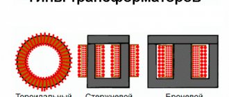
Types of transformers
Depending on the shape of the magnetic circuit, there are three types of transformers:
- Armored. It has a square shape with two side, one central and two transverse rods. In this case, only the central rod is effectively used. It is on this that the winding is put on. Therefore, the efficiency of this device is not very high. Forms two turns of magnetic field. This transformer is designed for heavy loads. This explains its very heavy weight.
- Rod. In some ways similar to the first type. The shape is half of an armored magnetic circuit. It consists of two lateral cores and two transverse ones. The magnetic field is single-turn, and, as a result, it has less power. The efficiency of such a transformer is 40%.
- Toroidal. It got its name due to its original shape. In mathematics there is such a thing as a toroidal surface. To put it simply, it is a voluminous circle or donut shape. Thanks to this shape of the magnetic core, toroidal transformers have the highest level of efficiency, approaching 100%. Therefore, such transformers are always smaller in size with the same power compared to other types. Due to the fact that the windings are evenly distributed over the entire area of the core, more efficient cooling of the turns occurs. Which, in turn, allows such devices to be loaded to the maximum without the risk of overheating.
How to do
Even young electricians can make a toroidal transformer. Winding and calculation are not complicated. We suggest considering how to properly wind a toroidal magnetic circuit for a semi-automatic machine:
- A special machine can be used to wind a transformer on a ferrite core. It will help significantly speed up work and reduce the likelihood of iron jumping off. It can be made as a clamp for wrapping wires;
- It should be noted that the latres that are needed for winding must be the same size. When winding, make sure that there are no gaps between the sheets. If your power transformer has small gaps in the magnetic circuit, then they can be filled with iron sheets from any other transformer, cut to a certain size;
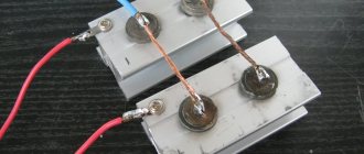
Photo - calculation - After winding of the iron is completed, its terminals are secured by welding. This will prevent the winding from unwinding. Literally two or three weld points are enough;
- After this, the ends of the magnetic circuit are coated with epoxy glue. The edges are first slightly rounded;
- Insulation is wound over the side of the amplifier - it can even be a sheet of cardboard. It can be attached using masking tape. We repeat the action on all surfaces of the magnetic circuit;
- Now you need to wrap textile tape around the cardboard insulation. It is sold in special electrical stores. On top of this layer of insulation you can wrap an additional layer of masking tape;
- Now a wire of the selected cross-section is screwed onto the ring; a special program will help you calculate the size of the wires and the required characteristics. After finishing the winding, everything is covered with NC varnish, one terminal of the winding should remain free;
Photo - winding the winding - Then you need to make insulation from varnished fabric or textile tape, on top of which the second winding is wound. It is also varnished. All that remains is to screw on the last insulation and protect it. Continue actions until the required number of windings is obtained;
Photo - tape wrapping - The secondary winding is wound from a larger wire cross-section. If a network transformer is needed for arc welding, then it is necessary to add a certain number of turns at the end, in addition to the calculated winding ones.
Plate materials
Transformer cores are made of either metal or ferrite. Ferrite, or ferromagnetic, is iron with a special crystal lattice structure. The use of ferrite increases the efficiency of the transformer. Therefore, most often the transformer core is made of ferrite. There are several ways to make a core:
- Made from stacked metal plates.
- Made from wound metal tape.
- In the form of a monolith cast from metal.
Any transformer can operate in both step-up and step-down modes. Therefore, all transformers are conditionally divided into two large groups. Boost: The output voltage is greater than the input. For example, it was 12 V, it became 220 V. Step-down: the output voltage is lower than the input. It was 220, but became 12 volts. But depending on which winding the primary voltage is supplied to, you can turn the step-down transformer into a step-up transformer, which will turn 10 A into 100 A.
Marking
Marking is the first stage, which is carried out if materials and tools are available. Careful research is important to determine the technical specifications.
It is acceptable to do it manually using special tables (but note that in this case you will have to calculate everything yourself using formulas).
You can also select markup using programs - there are some available for free on the Internet. But in this case, a novice radio amateur will not be able to understand the calculation algorithm and learn how to perform the frame independently, without the use of computerized equipment.
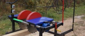
DIY toroidal transformer
A toroidal transformer, or simply a torus, is most often made at home as the main part for a home welding machine and more. In fact, this is the most common type of transformer, first manufactured by Faraday in 1831.
Advantages and disadvantages of the torus
Thor has undoubted advantages compared to other types:
- Relatively small in size.
- Very strong output signal.
- The windings are short and, as a result, these devices are characterized by low resistance and very high efficiency.
- Thanks to their shape, they are easy to install and also easy to dismantle if necessary.
The simplest torus consists of two windings on its ring-shaped core. The primary winding is connected to the source of electric current, the secondary winding goes to the electricity consumer. By means of a magnetic circuit, the windings are combined and their induction is enhanced. When the power is turned on, an alternating magnetic flux appears in the primary winding. Connecting to the secondary winding, this flux generates electromagnetic force in it. The magnitude of this force depends on the number of wound turns. By changing the number of turns, you can convert any voltage.
Calculation of the power of a toroidal transformer
Making a welding toroidal transformer at home begins with calculating its power. The main parameter of the future torus is the current that will be supplied to the welding electrodes. Most often, electrodes with a diameter of 2–5 mm are sufficient for domestic needs. Accordingly, for such electrodes the current power should be in the range of 110–140 A.
The power of the future transformer is calculated using the following formula:
U - open circuit voltage
cos f - power factor equal to 0.8
n - efficiency equal to 0.7
Next, the calculated power value is compared with the cross-sectional area of the core using the appropriate table. For home welding transformers, this value is usually 20−70 kV. cm depending on the specific model.
After this, using the following table, the number of turns of the wire is selected in relation to the cross-sectional area of the core. The pattern is simple: the larger the cross-sectional area of the magnetic circuit, the fewer turns are wound on the coil. The direct number of turns is calculated using the following formula:
U is the current voltage on the primary winding.
I - secondary winding current, or welding current.
S is the cross-sectional area of the magnetic circuit.
The number of turns on the secondary winding is calculated using the following formula:
Toroidal core
Toroidal transformers have a rather complex core. It is best made from special transformer steel (an alloy of iron and silicon) in the form of a steel strip. The tape is pre-rolled into a dimensional roll. Such a roll, in fact, already has the shape of a torus.
Read also: Carbon dioxide plus carbon
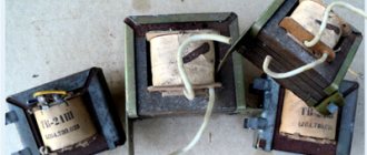
Where can I get a ready-made core? A good toroidal core can be found on an old laboratory autotransformer. In this case, it will be necessary to unwind the old windings and wind new ones onto a ready-made core. Rewinding a transformer with your own hands is no different from winding a new transformer.
Design
The first bipolar transformer was made by Faraday, and according to the data, it was a toroidal device. A toroidal autotransformer (brand Shtil, TM2, TTS4) is a device designed to convert alternating current from one voltage to another. They are used in various linear installations. This electromagnetic device can be single-phase or three-phase. Structurally consists of:
Photo - the principle of operation of the transformer
A device of this type is used in various audio and video installations, stabilizers, and lighting systems. The main difference between this design and other devices is the number of windings and the shape of the core. Physicists believe that the ring shape is the ideal design for an anchor. In this case, the winding of the toroidal converter is carried out evenly, as well as the heat distribution. Thanks to this arrangement of the coils, the converter cools quickly and even during intensive operation does not require the use of coolers.
Photo – finished TPN25
Video: purpose of toroidal transformers
Features of torus winding
The primary winding is made of copper wire in glass cloth or cotton insulation. Under no circumstances should rubber-insulated wires be used. For a current on the primary winding of 25 A, the wound wire must have a cross-section of 5-7 mm. On the secondary, it is necessary to use a wire of a much larger cross-section - 30-40 mm. This is necessary due to the fact that a much higher current will flow on the secondary winding - 120-150 A. In both cases, the wire insulation must be heat-resistant.
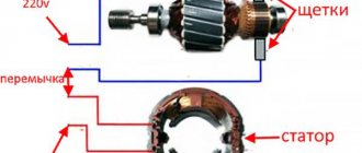
In order to properly rewind and assemble a homemade transformer, you need to understand some details of the process of its operation. It is necessary to correctly wind the wires. The primary winding is made using a wire of a smaller cross-section, and the number of turns themselves is much larger, this leads to the fact that the primary winding experiences very heavy loads and, as a result, can get very hot during operation. Therefore, the installation of the primary winding must be done especially carefully.
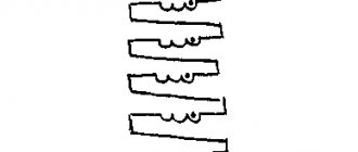
During the winding process, each wound layer must be insulated. To do this, use either a special varnished cloth or construction tape. The insulating material is pre-cut into strips 1-2 cm wide. The insulation is laid in such a way that the inner part of the winding is covered with a double layer, and the outer part, respectively, with one layer. After this, the entire insulating layer is coated with a thick layer of PVA glue. The glue in this case has a dual function. It strengthens the insulation, turning it into a single monolith, and also significantly reduces the humming sound of the transformer during operation.
Price overview
You can buy a toroidal transformer HBL-200 in any city in the Russian Federation and CIS countries. It is used for various audio equipment. Let's look at how much the converter costs.
Fedotov Alexey Gennadievich (UA3VFS) Gus-Khrustalny
The winding technology and the insulation method are actually very simple and in no case involve any kind of winding, varnished fabric, or anything else. The fact is that with any winding with varnished cloth or other insulators, the internal window of the TORA is instantly filled, since on the outside there is one layer, and on the inside there are 5-10 layers, and even uneven ones. I have long been planning to write an article about a method for high-quality winding of tori. This takes quite a long time to explain and is better shown in the photo. Moreover, after winding, the windings do not turn into a wheel, and the transformer itself does not become egg-shaped and wire consumption is minimal. In view of all this, the efficiency of the transformer is maximum. And what comes out of this, you can see in my amplifier.
Let me make a reservation right away: we are talking about powerful toroidal transformers. Overall power, which is more than 500W. Which are wound with wires from 1 to 3mm. naturally turn to turn. And, as a rule, the network winding of which lies in the range from 100 to 400 turns, in total, that is, 0.5-2 turns per volt. Winding less powerful transformers in this way is troublesome, but it is possible if desired.
What is needed for winding.
1) You need to make a stand for winding the toroid; this is done very simply. Take a square piece of chipboard or plywood 10-15mm thick. With dimensions of 200X200mm, we also need two wooden blocks 200mm long and 20X20mm square. We need to either glue these two bars in the center of our site, parallel to each other, with a distance of 100mm between them. It’s even better to screw these bars to the platform using screws, but with countersunk heads and recess the heads into the plywood, otherwise they will scratch the table. Now if you put a toroid on this stand, it will stand firmly and steadily. 2) You need a shuttle, I cut the shuttle out of plexiglass 5-6mm thick. The width is usually 30-40mm. length 300-400mm. I make the end cuts not at an angle, but in a semicircle and process them with a file so that the insulation of the wire does not deteriorate, and I even glue one or two strips of electrical tape, again to protect the wire. We wind the wire onto the shuttle; it’s okay if there isn’t enough wire, you can carefully solder the wire and wind it further. But it’s better to calculate it so that there is enough wire. 3) Now we need material for insulation between the layers, it’s very simple, you just need to find thin cardboard (packaging), for example, I use speaker boxes for cars. The main thing is that it is not a thick, but not thin material, the thickness of the cardboard is about 0.5 mm. If it is glossy on one side, then that is also good. 4) We also need thick threads, number 10-20. But at worst, number 40 is possible. The winding itself is carried out away from you to the right.
And now the most important thing is the manufacture of the insulating gaskets themselves between the layers. We will need a caliper with sharp ends.
We measure the outer diameter of our torus and add 20mm. (for overlap) and divide in half. For example, the outer diameter of the torus is 150mm + 20mm = 170mm. 170mm./2 = 85mm. We set the bar to 85mm. and fix it with a screw. We will use the rod itself as a compass for drawing circles on cardboard. Why use a barbell and not a regular compass, which is both easier and more convenient? And everything is very simple, when we draw on the cardboard with the sharp and durable end of the rod, a depressed groove will remain on the cardboard and it will help us. This groove is very useful for making it easier to bend the inner cut circle of our gaskets. In general, you yourself will understand that a barbell is better than a convenient compass. And so we draw the outer circle on the cardboard and cut it out with scissors; in principle, the outer circle can be drawn with an ordinary compass. Next, we measure the internal diameter of the torus, do not add or subtract anything, but simply divide it in half.
For example, diameter 60mm/2 = 30mm. We set the caliper caliper to 30mm. fix it with a screw and draw the internal diameter on cardboard. Next, we take a pencil and a ruler and work on the inner circle, first we draw a cross, that is, we divide the circle into 4 parts, then into 8 parts, if the inner diameter of the TOR is more than 60mm. then also into 16 parts. >Next, we draw another circle with a regular compass, which is half the size of the inner one, that is, we move the compass apart by 15mm. And now we need a flat piece of plywood or chipboard on which we will place our cardboard blank for cutting through our parts drawn in pencil with the end of a sharp scalpel or knife. You need to cut in a circle from the outer edge of the circle to the central point, no further, otherwise the cardboard will ride up. You need to cut right through the cardboard. Next, using scissors, we cut out the inner circle we drew with a regular compass. Bend the resulting slices perpendicular to the workpiece. It is clear that two such blanks are needed for each layer; each time the diameters are measured again, since their value changes from layer to layer. Next, measure the height of the torus and cut out two strips of cardboard of the same width. We insert one strip inside the torus, so that the overlap is no more than 10mm. We wind the second strip in one layer onto the outer side of the torus with the same overlap. We put both round blanks on the ends of the torus, fasten them with thread in three or four places in a circle. And then we begin to wind.