Despite the fact that household outlets are known to have an alternating voltage of 220 V, the vast majority of electronic devices require much lower values. Moreover, this power supply should be provided not by alternating current, but by direct current. That is why almost every household appliance has a rectifier - a diode bridge - as part of its circuit.
Direct and alternating current
From the physics course, everyone knows that electric current involves the flow of electric charge from one conductor to another. Unlike direct current, which actually flows in one direction (from negative to positive), alternating current flows first in one direction and then in the other. If you connect an oscilloscope to a power outlet, you can get a schematic representation of such current movement.
The figure shows an alternating current oscillogram, where the x-axis shows time and the y-axis shows voltage. The graph clearly shows that the voltage smoothly increases to a value of 220 V, then decreases to zero and increases to the same value, but with the opposite sign. In other words, the voltage in the outlet constantly changes sign at a rate of 50 times per second.
For comparison, you can connect the oscilloscope probes to a DC source. Battery terminals can be used as it. In this case, the picture will be somewhat different.
The DC waveform shown in the image clearly demonstrates how the terminal voltage remains constant throughout the entire time. When the circuit is closed, the current will flow in one direction.
A little theory about batteries
Any battery is a storage device for electrical energy. When voltage is applied to it, energy is stored due to chemical changes inside the battery. When a consumer is connected, the opposite process occurs: a reverse chemical change creates voltage at the terminals of the device, and current flows through the load. Thus, in order to get voltage from the battery, you first need to “put it down,” that is, charge the battery.
Almost any car has its own generator, which, when the engine is running, provides power to the on-board equipment and charges the battery, replenishing the energy spent on starting the engine. But in some cases (frequent or difficult engine starts, short trips, etc.) the battery energy does not have time to be restored, and the battery is gradually discharged. There is only one way out of this situation - charging with an external charger.
How to find out the battery status
To decide whether charging is necessary, you need to determine the state of the battery. The simplest option - “turns/does not turn” - is at the same time unsuccessful. If the battery “doesn’t turn”, for example, in the garage in the morning, then you won’t go anywhere at all. The “does not turn” condition is critical, and the consequences for the battery can be dire.
The optimal and reliable method for checking the condition of a battery is to measure the voltage on it with a conventional tester. At an air temperature of about 20 degrees, the dependence of the degree of charge on the voltage at the terminals of a battery disconnected from the load (!) is as follows:
- 12.6…12.7 V - fully charged;
- 12.3…12.4 V - 75%;
- 12.0…12.1 V - 50%;
- 11.8…11.9 V - 25%;
- 11.6…11.7 V - discharged;
- below 11.6 V - deep discharge.
It should be noted that the voltage of 10.6 volts is critical. If it drops below, the “car battery” (especially a maintenance-free one) will fail.
Correct charging
There are two methods of charging a car battery - constant voltage and constant current. Each has its own characteristics and disadvantages:
- Constant voltage charging - suitable for restoring the charge of not completely discharged batteries, the voltage at the terminals of which is not lower than 12.3 V. The process is as follows: a direct current source with a voltage of 14.2–14.7 V is connected to the battery terminals. The end of the process is monitored by the current consumption: when it drops to zero, charging is considered complete. The disadvantage of this method is that the initial charging current may be high; The more the battery is discharged, the higher the current. The advantages of the method are obvious - you do not need to constantly adjust the charging current, and the battery is not in danger of being overcharged if you forget about it.
- DC charging is the most common and reliable method. In this mode, the charger produces a constant current equal to 1/10 of the battery capacity. The end of the charging process is determined by the voltage on the battery - when it reaches 14.7 V, the battery stops charging. The disadvantage of this method is that the battery can be damaged if you do not remove it from charging in time.
Features of voltage types
A natural question arises about why alternating current is used in sockets, if the vast majority of electronic equipment is powered by direct current. The fact is that to power the nodes of this or that equipment, voltages of different magnitudes are required. A computer processor, for example, is powered by 3 V, and a mobile phone requires as much as 5 V to charge. A music center amplifier already needs about 25 V.
DC voltage is quite difficult to transform from one value to another, but alternating voltage is easy. For example, transformers are used for this. Some important power components, such as motors, still require AC power. Therefore, industrial generators that power household sockets produce it to a generally accepted value (for example, 220 V), and each device already receives from it what it needs on site.
Physical processes
The operating principle of a diode bridge is based on the ability of a pn junction to pass current in only one direction. A pn junction is understood as a contact between two semiconductors with different types of conductivity. The boundary separating the regions is characterized by the width of the forbidden zone, which prevents the passage of charges. On one side there is the p region, in which the main carriers are holes (positive charge), and on the other, the n region, where the majority carriers are electrons (negative charge).
Being isolated from each other, in each region the elementary particles perform random thermal vibrations, due to which their released energy is compensated and the resulting current is zero. When these areas come into contact, diffusion currents arise due to the attraction of charges to each other. As a result, the particles collide and recombine (disappear). In the contact zone, carriers become depleted and their movement stops. A state of dynamic equilibrium is established.
When an electric field is applied to the pn junction, the picture changes. With forward bias, that is, when the positive pole of the power source is connected to the p region, and the negative pole to the n region, the main carriers are introduced into the region. Because of this, the bandgap width decreases, and particles freely begin to pass through the barrier, forming a current. If the polarity of the power source is changed, then even greater depletion of the layers will occur, as a result, the barrier will increase, and the current will not arise.
Thus, depending on the polarity of the signal applied to the junction, the band gap increases or decreases. If an alternating signal is applied to an element whose operation is based on a pn junction, then as a result, forward and reverse voltage will be alternately applied to it. Accordingly, it will delay part of the signal and transmit part of it.
If you take a measuring device that can show the waveform (oscilloscope), then at the output of the radio element you can see pulses, the duration of which is determined by the half-wave period. That is why the diode is called a rectifier, although the name pulse converter is more suitable for it. That is, a device that converts an alternating signal into a burst of pulses.
You may be interested in Calculation of ground loop resistance in private homes
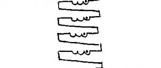
DIY rectifier bridge
Anyone who designs electronic devices cannot do without a rectifier. It is present in almost every homemade device powered from the network. In order to assemble a rectifier, it is not enough to take four diodes and twist their legs according to the diagram shown. In order for the bridge to work, you will have to become more familiar with the diodes and their characteristics before taking up the soldering iron. The main characteristics that will be needed when building a rectifier for semiconductors are as follows:
- Maximum permissible reverse voltage . The voltage that the diode can withstand when closed.
- Maximum permissible forward current . The current that the diode can withstand for a long time without damage.
- Direct voltage . The magnitude of the voltage drop across an open diode.
- Cutoff frequency . The AC frequency at which the device can still operate.
When assembling a mains rectifier capable of delivering a current of 1 A to a load, it is necessary to make a 12 volt diode bridge. This is what a practical bridge rectifier circuit looks like.
First of all, you need to calculate everything correctly and select the right type of semiconductors based on the available diodes. If you have diodes D226, KD204A, KD201A and D247 at your disposal, you need to open the reference book and familiarize yourself with their main characteristics (voltage, current and cutoff frequency):
- D226 - 400 V, 0.3 A, 1 kHz;
- KD204A - 400 V, 0.4 A, 50 kHz;
- KD201A - 100 V, 5 A, 1.1 kHz;
- D247 - 500 V, 10 A, 1 kHz.
All four types of diodes are suitable for voltage and frequency, but the first two will not withstand a current of 1 A. That leaves KD201A and D247. The decision to take one or the other depends on the design of the power supply. The first diodes are more compact, the second ones have a good current reserve.
Smoothing capacitor C1 must be selected according to type, electrical capacitance and voltage. You will need an electrolytic capacitor with a capacity of 1,000 to 20,000 μF with an operating voltage of at least 25 V. The higher the capacity of the smoothing capacitor, the better the quality of the rectified voltage, but the larger the design itself will be. All necessary information, including capacitance, polarity and operating voltage can be seen directly on the capacitor.
All that remains is to turn on the soldering iron and solder the circuit, not forgetting that electrolytic capacitors are polar devices. They have a plus and a minus, which should not be confused.
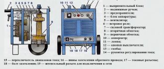
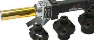
Manufacturing of welding machine
Today it is almost impossible and quite difficult to weld metal or process it in the proper way without using welding equipment. After you make a welding machine with your own hands, you will be able to perform any work with metal products.
Transformer circuit with a separate choke.
To produce a high-quality unit, you must have knowledge and skills that will help you understand the circuit of a DC or AC welding machine, which are two options for assembling equipment.
For home use, it is best to learn how to make mini welding.
It is more convenient to call a specialist or purchase a ready-made unit, but sometimes this can be too expensive, since it is quite difficult to determine the choice of model based on various parameters, such as the weight of the welding machine, and the number of volts per welding machine.
There are several types of welding machines: operating on alternating current, direct current, having three phases or inverter. To choose one of the options and start assembling, you need to consider each circuit of the first 2 types
During the preparatory process, you need to pay attention to the voltage stabilizer
AC
To make homemade welding machines, you need to select a voltage indicator, the best is 60 volts, the current is best adjusted from 120 to 160 amperes.
You can independently determine the cross-sectional value of the required wire for the manufacture of the primary winding of the transformer, which must be connected to a 220-volt network.
The cross-section according to the area parameters should not be more than 7 mm2, since it is worth noting the possible voltage drop and possible additional load.
Based on calculations, the optimal size of the diameter of the copper core for the primary winding, which reduces the action of the mechanism, is 3 millimeters. When choosing aluminum for the wire, the cross-section is multiplied by 1.6.
If the necessary wire is not available, it is possible to replace it with a slightly thinner wire, winding it in pairs. However, it must be remembered that the thickness of the winding will increase, which is why the dimensions of the welding equipment will be larger. For the secondary winding, a thick wire with a large number of copper cores is used.
DC
Electrical circuit of a DC welder.
Some welding machines operate using direct current. Thanks to this unit, you can weld cast iron products and stainless steel structures.
It may take no more than half an hour to create a DC welding machine with your own hands. In order to convert a homemade product with alternating current, it is necessary that the secondary winding be connected to a rectifier, which is assembled on a diode.
In turn, the diode must withstand a current of 200 amperes and have good cooling. To equalize the current value, you can use capacitors that have certain characteristics and voltage characteristics. After this, the unit is assembled sequentially according to the scheme.
Chokes are used to regulate current, and contacts are used to attach a holder. Additional parts are used to transmit current from an external carrier to the welding site.
Selecting a build type
Using a rectifier bridge instead of four diodes not only greatly simplifies the assembly, but also makes the design more compact. The principle of choosing the type of assembly is the same - according to voltage, current and frequency. To determine whether, for example, the KTs402G assembly, the photo and diagram of which are given above, is suitable, you need to consult the reference book. It contains the following characteristics of the bridge:
- maximum reverse voltage of diodes - 300 V;
- direct current of the entire assembly - 1 A;
- cutoff frequency is 5 kHz.
The bridge is suitable, but the microassembly will operate at the limit of its current capabilities. To ensure the reliability of the circuit, it is better to use a more powerful device. For example, bridge KTs409A for a current of 3 A or KTs409I for 6 A.
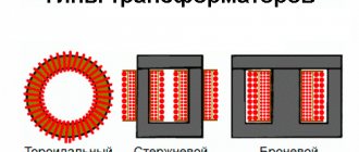
Transformers (with or without rectifier)
The heart of a transformer is the core. It is assembled from transformer steel plates, which are quite problematic to make by hand. By hook or by crook, the source material is extracted at factories, construction teams, and scrap metal collection points. The resulting structure (usually in the form of a rectangle) must have a cross-section of no less than 55 cm². This is a rather heavy structure, especially after laying the windings.
During assembly, it is imperative to provide an adjusting screw, with which you can move the secondary winding relative to the stationary primary.
In order not to go into the complexity of calculating the cross-section of wires, we will take typical parameters:
- secondary current 100–150 A;
- open circuit voltage 60–65 volts;
- operating voltage when welding 18–25 volts;
- current on the primary winding is up to 25 A.
Based on this, the cross-section of the primary wire should be at least 5 mm²; if you do it with a margin, you can take a wire of 6–7 mm². The insulation must be heat-resistant and made from a material that does not support combustion.
The secondary winding is made of wire (or better yet, a copper busbar) with a cross-section of 30 mm². The insulation is rag. Don't let the thickness scare you, the number of turns on the secondary is small.
The number of turns of the primary winding is determined by a coefficient of 0.9–1 turns per volt (for our parameters).
The formula looks like this:
W(number of turns) = U(voltage) / coefficient.
That is, with a network voltage of 200–210 volts, it will be about 230–250 turns.
Accordingly, if the secondary voltage is 60–65 volts, the number of its turns will be 67–70.
From a technical point of view, the transformer is ready. For ease of use, it is recommended to make a small margin on the secondary winding, with several branches (at 65, 70, 80 turns). This will allow you to work confidently in places with low network voltage.
Hiding the unit in the housing or leaving it open is a matter of safety of use. A typical DIY welding transformer looks like this:
The optimal material for the case is 10–15 mm textolite.
Adding a rectifier
A homemade powerful welding transformer from a circuit design point of view is a regular power supply. Accordingly, the rectifier is designed as simply as in a network charger for a mobile phone. Only the element base will look several orders of magnitude more massive.
As a rule, a pair of capacitors are added to a simple diode bridge circuit to dampen rectified current pulses.
You can assemble a rectifier without them, but the smoother the current, the better the quality of the weld. To assemble the bridge itself, powerful diodes of the D161–250(320) type are used. Since a lot of heat is generated on the elements when loaded, it must be dissipated using radiators. The diodes are attached to them using a bolt connection and thermal paste.
Of course, the radiator fins must either be blown by a fan or protrude above the case. Otherwise, instead of cooling, they will heat the transformer.
Mini welding transformer
If you do not need to weld rails or channels from 4–5 mm steel, you can assemble a compact welder for soldering steel wire (making frames for homemade products) or welding thin sheet metal. To do this, you can take a ready-made transformer from a powerful household appliance (the ideal option is a microwave) and rewind the secondary winding. Wire cross-section 15–20 mm², power consumption no more than 2–3 kW.
The calculation of the circuit is carried out in the same way as for more powerful units. When assembling the rectifier, you can use less powerful diodes.
Micro welder
If the scope of application is limited to soldering copper wires (for example, when installing distribution boxes), you can limit yourself to a design the size of a pair of matchboxes.
Performed on transistor KT835 (837). The transformer is manufactured independently. In fact, it is a high-frequency boost converter.
We wind the transformer on a ferrite rod. Two primary windings: collector (20 turns 1 mm), base (5 turns 0.5 mm). Secondary (boost) winding - 500 turns of 0.15 wire.
We assemble the circuit, solder the resistor circuit according to the circuit (so that the transformer does not overheat at idle), the device is ready. Power supply from 12 to 24 volts, with the help of such a device you can weld wire harnesses, cut thin steel, and join metals up to 1 mm thick.
A thick sewing needle can be used as welding electrodes.
Checking elements
Often in homemade devices it is necessary to use parts that have already been used. All such components must be inspected before installation. Since the rectifier assembly consists of four diodes connected back-to-back in series, and the terminals of all diodes can be reached with a probe, the question of how to ring a diode bridge can be solved simply.
To do this, it is enough to measure the resistance of each diode with a regular ohmmeter, focusing on the rectifier circuit and the bridge pinout. In one polarity of the probes, the device should show high resistance, in the other - low. When the corresponding diode is broken, the resistance will be low in both positions of the probes; if it is burned out, it will be high.
Using the Schottky barrier
Another basic characteristic that was not used in previous calculations is the forward voltage drop across the on-diode. A diode only theoretically conducts current in one direction, and a dielectric in the other. In practice, in a direct connection, the voltage drops on the device, which can reach 1.5 V or more.
This means that the voltage at the output of a half-wave rectifier will be lower than the input by 1.5 V, and if you use a bridge circuit, then by all 3 V. In addition, the volts multiplied by the current flowing through the rectifier will be uselessly dissipated on the diodes in the form of heat , reducing the efficiency of the circuit.
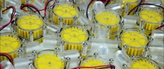
Diodes with a Schottky barrier allow you to avoid such troubles. They are characterized by a low (tenths of a volt) forward voltage drop, which means that the circuit assembled on them will have higher efficiency and operate in a lighter mode. The view and diagram of a powerful Schottky diode assembly are shown in the image.
Today, both individual diodes and Schottky diode bridges are used very widely as rectifiers and are produced both as individual devices and assemblies. Installing a rectifier using Schottky diodes is no different from assembling a rectifier using conventional diodes.
Originally posted 2018-07-04 08:35:05.
History of invention
In 1873, the English scientist Frederick Guthrie developed the operating principle of directly heated vacuum tube diodes. A year later, in Germany, physicist Karl Ferdinand Braun suggested similar properties in solid-state materials and invented a point rectifier.
In early 1904, John Fleming created the first complete tube diode. He used copper oxide as the material for its manufacture. Diodes have begun to be widely used in radio frequency detectors. The study of semiconductors led to the invention of the crystal detector in 1906 by Greenleaf Witter Pickard.
In the mid-30s of the 20th century, the main research of physicists was aimed at studying the phenomena occurring at the metal-semiconductor contact boundary. Their result was the production of a silicon ingot with two types of conductivity. While studying it, in 1939, the American scientist Russell Ohl discovered a phenomenon later called the pn transition. He found that depending on the impurities existing at the interface of two semiconductors, the reducibility changes. In the early 50s, Bell Telephone Labs engineers developed planar diodes, and five years later, germanium-based diodes with a transition of less than 3 cm appeared in the USSR.