Description
The set of automatic equipment included in the proposed welding complex is designed to perform circumferential and longitudinal butt welded joints of cylindrical containers. Welding is performed using automatic submerged arc welding from the outside and inside.
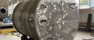
The welding complex can be used for welding cylindrical containers made of low-carbon, low-alloy and stainless steels in the production of power equipment, boilers, chemical and oil and gas processing equipment. The welding complex can also perform welding of straight butt welds of sheet parts (welding of flat cards), surfacing of flat, annular and circular parts.
The automatic complex equipment set includes:
- Welding column INCZ 4x4 (on a motorized rail trolley, manually rotated around a vertical axis).
- Automatic welding head INMZ9. The head is equipped with a motorized cross support and a 1000 A inverter power supply.
- Mechanical joint tracking system.
- Flux supply and recirculation system (compressed dry air of 6 atm is required for operation).
The set can be supplemented with a self-centering roller rotator INZT-10t (1 drive section + 3 idle sections) on rail bogies, 20T set. Rail tracks are not included in delivery.
Welding column INCZ 4×4, INTEGRAL
Welding column with retractable lifting arm, specially designed for fully automatic welding. The vertical rotary column and the retractable horizontal console are made of square-section rolled steel and provide high strength and reliability of the column's load-bearing structure. The column is mounted on a support bearing and has the ability to rotate around a vertical axis, manual rotation with mechanical fixation in any position.
A saddle is attached to the vertical column, in which the retractable console is located. The steel console saddle is mounted on 4 adjustable V-shaped casters; Each roller rotates on a sealed bearing and moves on an eccentric axis for precise console alignment. The saddle rollers ride on machined column guides to ensure smooth lifting of the console. The saddle with console moves up and down along the vertical column guides using a multi-link durable roller chain. The vertical movement drive is a gear reducer with an AC electric motor with an inverter frequency controller of the drive. The vertical movement drive ensures smooth, fast and precise lifting of the console to the required height.
A counterweight built into the column facilitates the operation of the vertical movement drive, which ensures smooth movement of the console up and down and reliable fixation at the required height. The safety system protects the console from falling, making the operation of the welding column safe.
The rectangular retractable arm has full length ground guides and a precision rack gear for movement within the saddle and is supported on 4 adjustable V-shaped rollers mounted on the saddle, each rotating on a sealed bearing and moving on an eccentric axis to ensure precise alignment and vibration-free movement of the automatic welding head.
All elements of the electrical equipment of the column have a degree of protection IP 54. The supply voltage of all electrical equipment of the column is 380 V, 3 phases, frequency 50 Hz. The cabinet with elements of electrical equipment and the control panel are mounted on a vertical column. The remote control is removable and connected to the cabinet with a wire.
Technical characteristics of the column INCZ 4×4, INTEGRAL
| Vertical movement of the console (A) | 4000 mm |
| Horizontal movement of the console (B) | 4000 mm |
| Speed of vertical movement of the console | 800 mm/min |
| Speed of horizontal movement of the console (with smooth adjustment) | 150 – 2500 mm/min |
| Maximum load at the end of the console at full reach | 200 kg |
| Overall dimensions when the console extends: | |
| minimum | 1250 mm |
| maximum | 5250 mm |
| Vertical size | 6300 mm |
| Supply voltage | 380 V, 3 phase, 50 Hz |
| Total installed capacity | 6.5 kW |
| Speed of movement of the rail trolley | 2000 mm/min |
Welding technology and methods
There are several welding methods for uneven workpieces. Choosing the right method will depend on how large the area needs to be welded and what shape the seam should be.
To weld pipes with a diameter of more than 30 cm, a circular reverse-stage method will be required. Here, each small section is welded clockwise, but these welded sections will appear in the reverse order, counterclockwise. That is, at the beginning of the first section the second will end, etc.
Reverse-step welding method for circumferential seams over 300 mm
More practical than reverse-stage ring welding would be multilayer welding. The principle here is that the ends and beginnings of adjacent layers overlap each other. And with each subsequent weld, the welding direction should be reversed. The size of each welded section on the ring part here does not exceed 25 mm.
Multilayer welding of circumferential seams
There is also a method of ring welding crosswise. It is usually used for pipes with a diameter of more than 1000 mm. Here the welds are divided into separate sections, usually four or more. Each section is divided into two more. This results in at least eight points at which the part needs to be welded. They are not numbered in order, but crosswise. And to maximize the effect, it is better for two welders to work here at once.
Cross welding of circumferential seams over 1000 mm
In addition to the correct method, you will also need to choose a suitable electrode. For example, when gas-protective electrodes are used, the seam should be made counterclockwise, without hesitation. To do this, one electrode will have to rest on the part itself that is being welded.
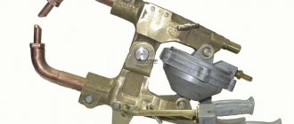
Automatic welding head INMZ9
At the end of the retractable console of the welding column there is an automatic welding head INMZ9 for submerged arc welding. The automatic welding head provides welding with a maximum welding current of 1000 A at 100% duty cycle with welding wire with a diameter of up to 5.0 mm. The unwinding device for welding wire is designed for coils of 25 kg wire and is placed directly on the console of the welding column.
Technical characteristics of the welding head
| Drive power | 150 W, 110 V |
| Wire feed speed when rotating the motor 14 rpm | 400-2000 mm/min (for wire ø3.2; 4.0; 5.0 mm.) |
| Wire feed speed when rotating the motor 47 rpm | 1350-6000 mm/min (for wire ø2.0; 2.4; 3.2 mm.) |
* Can be used with INZD5 and INZD7 series welding sources with power up to 1600A.
Result
Photos of the finished, smooth seam indicate that we have successfully completed the task.
Before:
After:
Of course, to obtain an ideal result, it is necessary to more precisely adjust the parameters of the welding source and carriage. But in general, we can say that the configuration coped with the task perfectly. The tractor independently monitors the seam, and the operator does not have to change anything during the process.
I would also like to draw your attention to the fact that this set of equipment will allow you to perform other tasks, for example, welding long straight (longitudinal) seams in any position .
Mechanical joint tracking system
The automatic welding head is mounted on a cross slider (sliding support) with a drive movement of 100 mm in the vertical and horizontal planes. The slider drive is two electric DC motors with lead screws and ball screws. The cross slider is controlled from a portable control panel.
The welding head is equipped with a contact-type mechanical vertical joint tracking system, which ensures constant ejection of the welding wire from the current-carrying nozzle.
Additionally, the welding head is equipped with a point laser designator to facilitate tracking of the weld joint. The target designator projects a light point with a diameter of less than 2 mm at a distance of 50 to 200 mm.
Manufacturing
A typical technological process for the production of shells includes the following stages:
- Cleaning the workpiece (removing scale and traces of corrosion).
- Performing straightening of sheet metal.
- Marking blanks, cutting them.
- Cutting sheets into blanks.
- Preparation of edges for welding work.
- Assembly of blanks.
- Performing card welding.
- Rolling (circular bending) of shells.
- Welding joints.
- Edit.
- Control.
Edge preparation
The operation is necessary to obtain the required edge shape and get rid of defects that arose when cutting the sheet. The shape of the edges must meet industry standards, specifications and requirements. Methods for processing the edges of shells for welding should not lead to mechanical damage. Possible options:
- Preparation of edges using an abrasive wheel with cleaning on both sides of the sheet plane in the areas of cutting edges and points of future welding, at a distance of 40 mm from the ends.
- Cleaning the edges using an electric grinder, on a tile stand, until cracks, rust, and scale are completely removed.
- Processing of edges using the milling method is carried out by securing the workpieces on the tables of milling machines of one type or another. Milling tools are milling heads and cutters. The edges for transverse seams in the bottoms and shells are processed on lathes and boring machines.
- Local edge cleaning and small amounts of work are performed using a pneumatic chisel.
Assembly of blanks
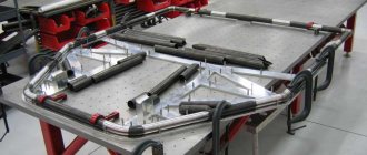
It is necessary to assemble workpieces for welding on special stands that will ensure the exact relative position of the parts and their fixation, GOST 26 291. The alignment of the joined elements is done using a square and a ruler or using stops. If the parts to be connected have different thicknesses, a smooth transition is made by gradually thinning the element of greater thickness. The workpieces to be joined are secured with clamps.
Rolling
Rolling of shells is the deformation of a sheet of metal along a certain direction. Depending on the thickness of the metal, rolling can be:
- cold (production of thin-walled shells);
- hot (thick-walled).
It is performed on a machine using rollers. The workpiece is placed between the shafts and, with their help, is bent to the required radius. To make a cylindrical shell, 3 shafts are needed, and a conical shell requires four.
Edit
This operation is especially necessary for cylindrical shells that have a rigid contour (not bending under their own weight). Due to the previously carried out stages - bending the edges and welding the longitudinal joint, the part acquires an irregular shape, with the greatest distortion in the heat-affected zone. The task of editing is to obtain a given geometric shape, in accordance with the conditions of regulatory documents. Straightening is performed between three rolls by increasing the curvature in the section of the shell contour located between the rolls, and then reducing it.
Final stage
In accordance with the requirements for the surface roughness of the product and the accuracy of the work, finishing work is carried out:
- zigging;
- beading and beading of ends;
- grinding.
Zigging
Purpose:
- giving the shell additional rigidity;
- installation and fastening of support expansion rings used for installing partitions, plates, supports, gratings.
Zigging is carried out on zigovochny machines.
Beading the ends
The goal is to ensure a door-to-side assembly. The work is carried out on on-board machines. Possible options: beading outwards and inwards.
End flanging
Beading methods are similar to beading:
- inward (for cooling the bottoms and under the cooling jackets of heat exchangers);
- outward (for mounting slip-on flanges).
To perform the actions, flange-bead machines are used.
Grinding
It is a finishing method that can be carried out:
- a manual grinder powered by a pneumatic or electric drive;
- copyless (semi-free) grinding with pendulum heads.
Finished products are checked for compliance with regulatory specifications. The shells should not contain sharp edges, burrs or dents on the surface. Minor defects and abrasions are acceptable that do not affect the reduction in wall thickness.
Welding power source INSAW, INTEGRAL
An inverter source for DC welding, model INSAW-1000IGBT (INZD7), is used as a current source.
| INSAW series inverter power supplies are multifunctional power supplies and can be used for automatic submerged arc welding, electroslag welding, stick welding, air carbon arc gouging, and also have good performance in single wire welding or DC strip surfacing. The main circuit of power supplies is an inverter circuit based on IGBT modules with high reliability, high response speed, good dynamic characteristics, they can quickly automatically compensate for fluctuations in supply voltage, ensure stable arcing and obtain a weld of good shape and high quality. |
| Supply voltage, V/Hz | ~3×380 V ±10% / 50 Hz |
| Rated power consumption, kVA | 53 |
| Rated current consumption, A | 80 |
| Power factor cosφ | 0,93 |
| Effective efficiency | 0,88 |
| Open circuit voltage, V | 83 |
| No-load current, A | 1,0 |
| Power loss without load, W | 484 |
| Welding current range, A | 100 — 1000 |
| Rated welding voltage, V | 44 |
| Rated Duty Cycle (DU) | 100% |
| Weight, kg | 125 |
| Dimensions (L × W × H), mm | 780×390×800 |
| Insulation class | F |
| Degree of protection | IP21S |
| Cooling mode | air |
Equipment for fastening and moving automatic and semi-automatic welding machines
Welding with automatic and semi-automatic machines can be carried out both without and with the use of special auxiliary devices, for example, for suspending the apparatus over a movable welded product or for moving the apparatus along a seam or from seam to seam (columns, portals, carts, platforms). Auxiliary equipment of this type is often used for welding with tractors or semi-automatic machines.
Rotary column for semi-automatic welding machine
Flux supply and recycling system
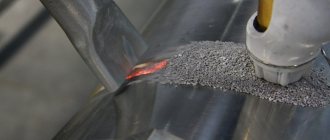
A pneumatically driven flux supply and recirculation system installed on the welding column console provides the supply of heated welding flux to the welding head and removal of excess flux from the weld using an ejection nozzle mounted on the welding head.
The removed flux enters a recirculation hopper equipped with mechanical and magnetic separators to restore the flux and remove the remnants of the remelted slag crust. The recovered flux enters the consumable flux hopper located directly on the welding head. To operate the flux supply and recirculation system, compressed air (dry and oil-free) with a pressure of 6 bar is required.
Technical characteristics of the flux supply and recirculation system
| Main hopper capacity | 50 kg |
| Small hopper capacity | 6 kg |
| Pump motor power | 3.0 kW |
| Supply voltage | ~380V, 3ph |
| Compressed air pressure | 0.6 MPa |
| Working negative pressure (suction) | -0.02 MPa |
| Horizontal flux supply distance | 8-25 m |
| Vertical flux supply distance | 5-7 m. |
| Flux recovery rate | 8 -15 kg/min |
| Flux feed rate | 2- 20 kg/min |
| Main unit weight | 150 kg |
Technological equipment of welding installations
Flux-holding devices are used to create the necessary layer of flux in cases where this layer is not retained by the edges of the parts being welded. Flux-holding devices can be fixed or movable. Schemes of some of them are shown in the figure.
Flux pads are used to prevent leakage of molten metal into the gap between the edges. A layer of flux is pressed against the underside of the weld, holding the weld pool and forming a back bead.
Self-adjusting roller rotator INZT-10T
The self-centering roller rotator on rail bogies consists of 4 sections: INZT-10T - 1 drive and 3 idle sections - with a total load capacity of 20 tons.
The rotator is a robust structure on a steel frame. Each section of the rotator has two supports, on the axis of which rocker arms with four rollers coated with a layer of technical polyurethane are installed. The upper rollers of the drive section have locking devices to prevent damage to the transmission when loading products. The drive section is equipped with two AC motors with worm gearboxes. The rotation speed of the rollers is controlled by a frequency converter, which allows you to set the required rotation speed.
All electrical components are installed in a cabinet mounted on the drive section bracket. The roller rotator is controlled from a remote control, on which the rotation speed is set using a potentiometer, as well as a rotation direction switch and an emergency stop button. The remote control connection cable is 10 m.