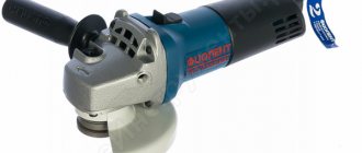
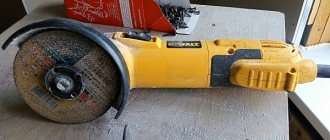
Angle grinders (angle grinders, angle grinders) under the German brand Bosch are distinguished by high quality, reliability and durability. The main competitive advantage of Bosch angle grinders lies in the widespread use of innovative technologies in the manufacture of the product.
But German quality cannot resist Russian negligence. Incorrect use of the tool, untimely replacement of lubricant, carbon brushes, bearings leads to tool failure.
In order to repair a Bosch angle grinder, you can go in two ways: take the angle grinder to a service center or repair the Bosch angle grinder yourself.
The first option is more expensive and not always of high quality. The second option can only be implemented if the consumer has a strong desire to figure everything out on their own.
The Bosch angle grinder diagram will help you carry out the repair yourself.
Bosch grinders are conventionally divided into low-power ones up to 1000 W, and powerful ones over 1000 W and are marked GWS 7-125, GWS 20-230 or others.
Deciphered
The first number 20 or more indicates the power of the instrument is more than 1000 W. The second number 230 certifies that this is the maximum diameter of the cutting wheel.
The first number up to 20 indicates the power of the tool up to 1000 W, and the second indicates the maximum diameter of the cutting wheel up to 125 mm.
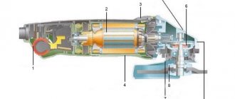
Design features of the Bosch angle grinder
A design feature of the Bosch grinder is represented in the use of a gearbox as a support bearing for the driven helical gear of a needle bearing. In Bosch rotary hammers, the driven gear is attached to the spindle shaft by pressing.
In low-power Bosch angle grinders, in which spur gears are installed in the gearboxes, the installation of shims is provided. This design allows you to restore the functionality of the gear contact by reducing the thickness of the gasket. At high tool speeds, helical gears wear out significantly less than spur gears.
The work environment for grinders is most often a dusty space. Dust is the main danger leading to failure of power tools, grinders and grinders.
Speed controller and soft start for grinder
Both are necessary for reliable and convenient operation of the power tool.
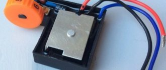
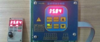
What is a speed controller and what is it for?
This device is designed to control the power of an electric motor. With its help you can regulate the speed of rotation of the shaft. The numbers on the adjustment wheel indicate a change in the rotation speed of the disk.
Angler speed regulator
The regulator is not installed on all angle grinders.
Grinders with speed controller: examples in the photo
The lack of a regulator greatly limits the use of the grinder. The rotation speed of the disk affects the quality of the grinder and depends on the thickness and hardness of the material being processed.
If the speed is not regulated, then the speed is constantly kept at maximum. This mode is only suitable for hard and thick materials, such as corners, pipes or profiles. Reasons why a regulator is necessary:
- Thin metal or soft wood requires a lower rotation speed. Otherwise, the edge of the metal will melt, the working surface of the disk will become washed out, and the wood will turn black from the high temperature.
- To cut minerals, it is necessary to regulate the speed. Most of them break off small pieces at high speed and the cutting area becomes uneven.
- To polish cars, you do not need the highest speed, otherwise the paintwork will deteriorate.
- To change a disk from a smaller diameter to a larger one, you need to reduce the speed. It is almost impossible to hold a grinder with your hands with a large disk rotating at high speed.
- Diamond blades should not be overheated to avoid damaging the surface. To do this, the speed is reduced.
Tools needed for repairs
To repair a Bosch angle grinder, you cannot do without tools. Let’s make a reservation right away: if you have a screwdriver, this will significantly speed up the process of disassembling and assembling the tool.
But you can get by with a set of screwdrivers, preferably with a ratcheting mechanism. You cannot do without an open-end wrench, which you will use to unscrew the nut securing the drive helical gear.
To remove bearings, it is better to have a special puller.
Diagnostics of the electrical part can be carried out using a tester or a device for determining short circuits of turns.
It is especially useful in that it allows you to determine whether the rotor or stator is faulty without removing the assembly.
The Bosch angle grinder diagram will help you carry out the repair yourself, and these instructions will help you adequately cope with any problem.
Final stage
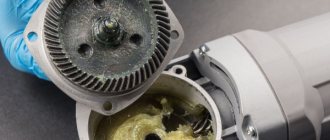
After all the necessary repairs have been carried out, the angle grinder is reassembled in the same sequence as it was disassembled. But before assembly itself, it is necessary to lubricate all mechanical components of the angle grinder.
For this purpose, experts recommend domestically produced lubricants. On the shelves of stores selling household electrical appliances you can find lubricants from foreign manufacturers, but they are much more expensive, although their quality is no better than domestic ones. Among the huge selection of lubricants, you should choose those products that have high adhesion rates (they are recommended for gearboxes of all angle grinders). Such lubricants adhere better to the surface.
Do-it-yourself Bosch grinder disassembly
For the owner of a power tool, knowledge of its structure and the ability to disassemble it is a mandatory task.
Knowing the procedure for disassembling an angle grinder allows you to independently carry out work such as changing grease, changing bearings and carbon brushes.
To disconnect the gearbox housing pos. 821 from the stator housing pos. 888, you need to disassemble (remove) the body of the grinder handle pos. 24.
This operation must be performed to remove the carbon brushes pos. 810 holding the rotor commutator.
At the second stage, unscrew 4 (four) screws, pos. 61, securing the gearbox and stator housings.
Having pulled out the rotor together with the gearbox, begin disassembling the gearbox.
Repair of a Bosch angle grinder begins with disassembling the gearbox pos. 821. Disassembling the gearbox begins with unscrewing 4 (four) screws, pos. 60. As a rule, the screws are screwed in with sealant at the factory. You will have to make some effort.
Let's note it right away! Low-power Bosch angle grinders use spur gears in the gearbox. Grinders with a power of over 1000 W use helical gears in their gearboxes.
How to remove the driven gear
By removing the gearbox cover, you can get the helical gear assembly, pos. 26.
To remove the gear, you need to use a press or puller. But using a puller is difficult because it requires the use of special thin jaws.
Before removing the helical gear, check the backlash of the gear connection, the integrity of the teeth, and the contact patch.
A bearing, pos. 50, is pressed onto the spindle shaft, pos. 26. If the bearing has a lot of play, is noisy when turning, or the lubricant has dried out, it is preferable to replace it.
To remove the bearing, you need to remove the gear, retaining ring and dismantle the bearing. If, when dismantling the rotor shaft assembly, the bearing remains in the gearbox housing, dismantling the bearing is carried out using a hammer and a soft tool.
How to remove the drive gear of a Bosch angle grinder
The drive gear pos. 27 is removed from the rotor shaft in the following sequence:
- Hold the rotor with your hand and, using an open-end wrench, unscrew the nut pos. 45 counterclockwise;
- remove the washer pos. 59.;
- pull out the drive helical gear pos.27.
Visually check the integrity of the gear teeth and contact patch.
If the gears are heavily worn (licked), or there are chipped teeth, they must be replaced. Moreover, gears are always replaced in pairs.
Low-power Bosch angle grinders use a needle bearing as a support bearing in the gearbox.
Repair your Bosch earmachine guns with your own hands, strictly follow the included instructions. If you need to remove a needle bearing from its housing, some quick thinking is required. Its dismantling is carried out only when destroyed.
To remove a damaged bearing race, you can use a proven method.
Select a tap with a diameter slightly larger than the inner diameter of the damaged needle bearing race. The tap is secured in the screwdriver chuck and carefully screwed into the holder at low speeds. When the tap reaches the bottom of the gear housing, it will begin to lift the cage.
In addition to the needle bearing of the spindle shaft, Bosch angle grinders use two more bearings mounted on the rotor shaft.
How to remove bearings from the rotor of a Bosch angle grinder
To remove bearings from the rotor pos. 803 of a Bosch angle grinder, it is recommended to use pullers.
Bearing pos. 15 near the manifold can be easily removed, but removing bearing pos. 14 from the impeller side is complicated by the fact that a number of preparatory operations must be performed.
Bearing pos. 15 is closed with a soft rubber seat. A similar rubber protection, pos. 33, also covers the bearing, pos. 14.
To dismantle the bearing pos. 14, you need to unscrew the nut pos. 45, remove the spur gear pos. 17 and the plastic protection pos. 33. Using a puller, you can easily remove the bearing from the rotor shaft.
What if there is no puller? A vice, two metal strips and a hammer with a soft metal attachment will come to the rescue.
Disassembling a Bosch grinder
How to make a regulator from a dimmer?
A very effective and easy solution to this issue would be to create an external frequency converter. A dimmer can be used as a converter - a device for regulating the light level. When creating, you will need an electrical outlet and plug. It must be said that the implementation of such a device can be performed using different methods. Two are especially simple: with and without the use of a machine gun.
- Screw 2 wires to the ends of the electrical outlet so that one is longer. After this, connect the long end to one of the contacts on the plug. Fix the end of the 2nd wire to the dimmer contacts, and connect its other output to the 2nd contact of the plug.
- When using the 2nd option, it is necessary to make a number of modifications to the circuit, and specifically to place a machine on the cord between the plug and the dimmer. Basically, dimmers have ordinary switches, but we need an automatic one, which, if something goes wrong, will turn off our device from the mains.
So, the frequency converter of the angle grinder is ready, and for practicality it can be placed in a specialized housing or fixed on a wood panel. You just have to take into account that such a device is homemade, and when working with the electrical network, you need to be careful.
To learn how to make a speed controller for an angle grinder with your own hands, see the video below.
Do you have an angle grinder, but no speed controller? You can make it yourself.
Possible electrical faults
Malfunctions of the electrical part of a Bosch angle grinder can be divided into simple and complex.
Simple malfunctions of the electrical part of the Bosch angle grinder
If you turn on the angle grinder and it refuses to work, start looking for the problem with a broken power supply wire. Most often, a wire break appears at the entry point into the angle grinder or into the plug. Avoid twisting, as this will cause a short circuit in the tool.
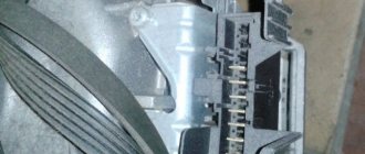
To determine such a malfunction, it is necessary to open the covers of the grinder handle. In Bosch angle grinders up to 1000 W, the lid is secured with one screw at the end. For Bosch angle grinders over 1000 W, the handle cover is secured with several screws.
Using a tester, test the power circuit from the input plug pos. 5 to the switch. If the circuit is intact, proceed to check the operation of the switch. Bosch angle grinders use simple switches controlled by a power lever.
But the electrical contacts of the switch burn out and cause the grinder to fail. It is not practical to restore the contacts of the plastic switch; it must be replaced with a new one.
If the switch is intact, use a tester to check the presence of a circuit from each pin of the plug to each carbon brush. If the circuits are intact, the angle grinder should turn on. If it does not rotate, then there is a mechanical fault. Gears may jam or bearings may be damaged.
Checking the electric motor
If your Bosch grinder picks up speed regardless of you, starts to get very hot and sparks, you need to pay attention to the integrity of the rotor and stator windings.
An involuntary increase in engine speed indicates a malfunction of the stator windings. The integrity of the windings is checked with a tester, and a short circuit between the turns is checked with a special device.
How to determine whether a rotor is faulty
Rotor repair is a complex technological process accessible to skilled craftsmen.
A rotor malfunction is indicated by a drop in engine speed and the appearance of a long sparkling trail on one of the brushes. This is the first sign of a short circuit in the armature winding turns.
It is preferable to carry out rotor repairs in special workshops. Or you can rewind it yourself if you decide to repair the Bosch angle grinder yourself.
The dark color of the rotor winding and burnt commutator lamellas indicate a short circuit in the rotor circuits. The malfunction can only be eliminated by replacing it with a new rotor.
Stator repair
Repair of a Bosch angle grinder includes restoration of the stator. The main sign of stator failure is a spontaneous increase in the speed of a working angle grinder, which cannot be reduced by adjustments. The burnt stator winding changes color and becomes darker. The stator core also darkens due to high temperature.
It is easier to rewind the stator, although here you must follow certain rules and sequence.
If you have removed the stator housing cover, carefully inspect the condition of the carbon brushes and lamellas of the rotor commutator.
The length of carbon brushes should not be less than 8 mm. By the way, Bosch angle grinders use carbon brushes with a “shot”, a device that stops the operation of the angle grinder when the carbon brush is at a minimum length.
The collector lamellas should not show signs of carbon deposits or wear. Carbon deposits are easily removed with cotton wool soaked in alcohol.
Stator overheating and rotor short circuit
Speed controller malfunctions
Bosch series angle grinders, especially low-power ones, have speed controllers. Access to the speed controller is achieved by opening the handle of the stator housing, which is held on by one end screw.
The speed range of the regulator can be set using a potentiometer hidden in the handle panel.
The faulty regulator is quite easy to remove, since it is attached only to the guide.
Repairing an angle grinder speed controller is a complex process, the implementation of which requires not only special knowledge, but also tools and equipment.
If the speed controller is faulty and there is no new one, then disconnect the supply wires and install a jumper.
The jumper that is installed when the speed controller fails is shown in red.
Why does an angle grinder need a soft start and a speed controller?
Modern angle grinders use 2 necessary options that increase the performance and safety of the equipment:
- speed controller (frequency converter) – a device designed to convert the speed of the motor in different operating modes;
- soft start device - a circuit that ensures a leisurely increase in engine speed from zero to the maximum value when the unit is connected.
They are used in electromechanical equipment, the structure of which is an AC electric motor with a commutator. Helps reduce wear on the mechanical parts of the unit when turned on. They reduce the load on the electrical components of the machine, putting them into operation smoothly. As studies of the qualities of materials have revealed, especially strong production of contacting nodes occurs during the process of a sudden transition from a stationary state to rapid activity. For example, one start of an internal combustion engine in a car is equivalent to 700 kilometers of wear on the piston and a group of sealing rings.
When power is supplied, an abrupt transition is made from a stationary state to the rotation of the circle with a rapidity of 2.5-10 thousand revolutions in 60 seconds. Anyone who has used an angle grinder knows very well the feeling that the tool literally “flies out of your hands.” It is at this moment that most of the accidents involving the mechanical part of the unit happen.
The rotor and stator windings feel no less load. The AC electric motor with a commutator starts in short circuit mode, the EMF is already pushing the shaft forward, but the inertial force does not yet allow it to rotate. A jump in starting electric current occurs in the coils of the electric motor. Despite the fact that by design they are designed for such work, over time a moment comes (for example, during a voltage drop in the electrical network) when the winding insulator is not able to withstand and a short circuit occurs between the turns.
When you introduce into the electrical circuit an instrumentation of circuits for adjusting soft starting and changing the motor speed, all the above-described troubles spontaneously disappear. In addition, the issue of a sudden and significant decrease in voltage in the general electrical network during the start-up of the tool is resolved. From this it is clear that household electrical appliances will not be at risk of failure. And the automatic switches on the electric meter will not operate and turn off the current in the apartment or house.
The soft start circuit is used in angle grinders of the middle and high price segment, the speed control unit is used more and more in professional modifications of angle grinders. Regulating the speed makes it possible to process soft materials with an angle grinder , to carry out delicate grinding and polishing, since at high speeds the wood or paint will simply burn. An auxiliary electrical circuit increases the price of the instrument, but extends the service life and degree of safety during use.
Mechanical damage
The Bosch angle grinder is designed to perform cutting, grinding, and polishing work. Operating a tool in dust under heavy loads has a particularly detrimental effect on the durability of the gearbox, namely its gears.
In addition to wear and breakage of gear teeth, mechanical failures include destruction of bearings and housings. Repairing a Bosch angle grinder in terms of replacing failed bearings and restoring the housing is not difficult to do if there is a desire and need.
Assembling the grinder
The assembly of the grinder begins with an examination of all parts, assemblies, bearings, and gears.
Pre-prepare the workplace with proper and good lighting, place tools, lubricants, and napkins.
What lubricant to use for a Bosch angle grinder
Bosch ear repairs will not be of high quality if you do not change the lubricant during the repair. For high-quality lubrication of Bosch angle grinder components, it is recommended to use those lubricants offered by the tool manufacturer. But their high price forces us to look for another way out, and there is one.
Domestic manufacturers of lubricants have developed special lubricants for gearboxes and components of angle grinders.
In terms of quality, they are in no way inferior to foreign lubricants, and are much cheaper. The only negative is that our lubricants require more frequent changes.
Or you can use a self-made lubricant.
Rotor assembly
Assembling the rotor consists of pressing bearings onto it and installing the impeller. Lubricated bearings are pressed onto the shaft using a wooden extension. The bearing near the collector is covered with rubber protection. This is the general algorithm for assembling the rotor shaft.
Some models of Bosch angle grinders have their own characteristics.
Gearbox assembly
Assembly of the gearbox begins with the installation of the rotor shaft into its housing. Once the shaft is inserted into the housing, the drive gear, washer and locking nut are placed on the shaft. The gearbox housing with the inserted shaft must be placed in the stator housing.
Once you have the commutator bearing in place, press the gear housing against the stator housing. Check the ease of rotation of the rotor in the bearings.
A spindle assembly with a mounted bearing and gear is mounted in the gear housing cover.
All that remains is to insert the cover into place and check the quality of rotation of the spindle shaft. If the shaft rotates easily by hand, it is possible to tighten the screws securing the rotor housing cover. The screws are pre-lubricated with sealant.
This is a general algorithm for assembling a gearbox. For some models, the repair of the Bosch angle grinder gearbox is slightly different.
Conclusions:
- Knowing the general layout of Bosch angle grinders, you can safely begin disassembling the tool for lubrication;
- The ability to repair a Bosch angle grinder with your own hands will allow you to extend the life of the tool, replace the lubricant and carbon brushes yourself;
- By observing the operating mode and technological maintenance of the tool, you will extend its trouble-free operation for many years.
Good luck in job!
Electronic unit in an angle grinder
The electronic unit allows you to combine the speed controller and soft start into one. The electronic circuit is implemented on the principle of pulse-phase control with a gradual increase in the opening phase of the triac. Grinders of different power and price categories can be equipped with such a block.
Almost all models of angle grinders in the lower price range lack such useful options as adjustable spindle speed and soft start. If you have the desire and some skills, you can make a speed controller for an angle grinder yourself, although it is much easier to purchase a ready-made electronic unit for several hundred rubles. Adjusting the rotation speed expands the capabilities of the angle grinder and allows you to use it to process soft materials at lower cutting speeds. In addition to the speed controller for an angle grinder, a very useful function is a soft start, which smoothes out a sharp increase in current in the electric motor windings at the moment voltage is applied to it. This prevents sudden increases in torque and “sagging” of the supply network. In addition, soft start reduces shock loads on the engine and gearbox of the angle grinder, which protects them from premature wear.
What is this function, principle of operation, electrical circuit, advantages of an angle grinder with a regulator
An angle grinder that is not equipped with a speed control device operates exclusively at maximum rotation speed. Equipped with this option, it allows you to reduce the rotation speed to a value that allows you to efficiently process materials, which is impossible at maximum mode.
The electronic unit of the speed controller is based on a modified dimmer principle, where the power is changed by manually changing the value of a variable resistor. With the help of electronic control of the current strength, the torque is maintained on the working shaft of the spindle, ensuring the functionality of the angle grinder. The main working elements of such a circuit can be either a semiconductor device triac or a more advanced version with an integrated circuit.
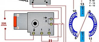
Connection diagram without power regulator
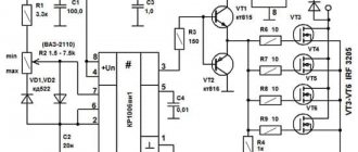
The electrical circuit of ordinary household angle grinders without additional options is shown in the figure:
Electrical diagram of an angle grinder. Photo source here
Here, two unconnected stator windings are connected to a voltage source (household network) through a switch, which has a manual start button in its design. Next, each of the windings is connected using special contacts to graphite brushes, which are pressed against the surface of the commutator using springs. In turn, the ends of the rotor windings are connected to the commutator lamellas, forming a closed electrical circuit.
The speed controller is connected to the open circuit between the on/off button and the stator windings when located inside the body of the angle grinder. If designed as a separate unit, it can often be located in a break in the network cable.
How to connect a capacitor with four terminals
Most often, a single-phase network with a voltage of two hundred and twenty V is supplied to our houses, plots, and garages. Therefore, equipment and all household products are made so that they operate from this power source. In this article we will look at how to properly connect a single-phase motor.
Selection of capacitors
There is a rather complex formula with which you can accurately calculate the required capacity, but it is quite possible to get by with recommendations obtained from many experiments:
- The working capacitor is taken at a rate of 0.7-0.8 µF per kW of engine power;
- Launcher. 2-3 times more.
The operating voltage of these capacitors should be 1.5 times higher than the voltage, that is, for a network of two hundred and twenty V, we take containers with an operating voltage of three hundred and thirty V and higher. And to make starting easier, look for a special capacitor in the starting circuit. They have the words Start or Beginning on the label, but you can use the regular ones.
Determining the capacitance of an unknown capacitor
Method No. 1: measuring capacitance with special devices
The easiest way is to measure the capacitance using a device that has a capacitance measurement function. This is already clear, and this was already discussed at the beginning of the article and there is nothing more to add.
If you're not very comfortable with instruments, you can try putting together a simple homemade tester. You can find good schemes on the Internet (more complex, simpler, very simple).
Well, or finally fork out for a universal tester that measures capacitance up to 100,000 µF, ESR, resistance, inductance, allows you to check diodes and measure the parameters of transistors. How many times has he helped me out!
Method No. 2: measuring the capacitance of two capacitors connected in series
Sometimes it happens that you have a multimeter with a capacitance measurement, but its limit is not enough. Typically, the upper threshold of multimeters is 20 or 200 μF, and we need to measure a capacitance of, for example, 1200 μF. What should we do then?
The formula for the capacitance of two series-connected capacitors comes to the rescue:
The bottom line is that the resulting capacitance Cut of two series capacitors will always be less than the capacitance of the smallest of these capacitors. In other words, if you take a 20 µF capacitor, then no matter how large the capacitance of the second capacitor is, the resulting capacitance will still be less than 20 µF.
Thus, if the measurement limit of our multimeter is 20 μF, then the unknown capacitor needs to be in series with a capacitor of no more than 20 μF.
All that remains is to measure the total capacitance of the chain of two capacitors connected in series. The capacity of an unknown capacitor is calculated by the formula:
For example, let's calculate the capacitance of the large capacitor Cx from the photo above. To carry out the measurement, a 10.06 µF capacitor C1 is connected in series with this capacitor (it was previously measured). It can be seen that the resulting capacitance was Ccut = 9.97 µF.
We substitute these numbers into the formula and get:
Method No. 3: measuring capacitance using the circuit time constant
As is known, the time constant of an RC circuit depends on the value of resistance R and the value of capacitance Cx: The time constant is the time during which the voltage on the capacitor decreases by e times (where e is the base of the natural logarithm, approximately equal to 2.718).
Thus, if you determine how long it takes for a capacitor to discharge through a known resistance, it will not be difficult to calculate its capacity.
To increase the measurement accuracy, it is necessary to take a resistor with a minimum resistance deviation. I think 0.005% will be fine =)
Although you can take a regular resistor with a 5-10% error and stupidly measure its real resistance with a multimeter. It is advisable to choose a resistor such that the discharge time of the capacitor is more or less reasonable (10-30 seconds).
Here's a guy who explained everything very well in the video:
Other ways to measure capacitance
You can also very roughly estimate the capacitance of a capacitor through the growth rate of its DC resistance in the continuity mode. This was already mentioned when talking about checking for a break.
The brightness of the light bulb (see the short circuit search method) also gives a very rough estimate of the capacity, but nevertheless this method has a right to exist.
There is also a method of measuring capacitance by measuring its resistance to alternating current. An example of the implementation of this method is the simplest bridge circuit:
By rotating the rotor of the variable capacitor C2, the bridge is balanced (balancing is determined by the minimum readings of the voltmeter). The scale is pre-programmed in terms of the capacitance values of the capacitor being measured. Switch SA1 is used to switch the measurement range. The closed position corresponds to a scale of 40...85 pF. Capacitors C3 and C4 can be replaced with identical resistors.
The disadvantage of the circuit is that an alternating voltage generator is required, plus preliminary calibration is required.
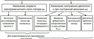
Use of asynchronous motors
Three-phase and single-phase asynchronous motors are actively used in various sectors of the economy. There are several reasons for this:
- Simplicity of design.
- Reliability and durability during use.
- In order to start the engine, there is no need to use expensive and scarce devices.
- The motor does not require too frequent maintenance.
By appearance, you can easily distinguish three-phase motors from single-phase ones. The former always have 6 terminals, while the latter have two or four.
For three-phase motors, the windings are connected in two ways: star or delta. They assume the use of a voltage of 380 volts. However, it is rarely used in everyday life. To use such a motor, you need to know how to connect it correctly.
This is done using a phase-shifting capacitor. This will allow the use of three-phase motors when connected to a single-phase network. In this case, the motor power will be equal to 50% -60% of the nominal.
Checking the starting capacitorSource antemion.ru
Optimal operation of a three-phase motor is ensured by using a variable capacitance. To do this, at the first stage, working and starting capacitors are used, and at the second, only the first of them.
Asynchronous single-phase motors are often used in everyday life. Additional winding is usually required to start.
When choosing the capacitance of a capacitor, it is necessary to take into account how the magnitude of the starting torque depends on it. As this characteristic increases, the force increases. At a certain value it becomes maximum. After a further increase, the starting torque will begin to fall.
Calculation of capacitor parametersSource uk-energotekhservice.rf
Launch scheme
The design of the grinder, the energy source of which is electric current, is capable of converting it into mechanical. The interaction of all components of the angle grinder is shown in the schematic diagram for connecting its electric drive.
- Once the power cord is plugged into the outlet and the starter is turned on, electrical current is applied to one of the brushes.
- After passing through the commutator winding, the current appears on another brush, through which the stationary stator windings are supplied with power.
- The magnetic fields created by the stator and rotor windings interact with each other, causing rotation of the rotor fixed in the bearings. Along with it, the torque occurs on the bevel gear mounted on the anchor. Another bevel gear, working in tandem with the first, rotates the spindle with the working tool of the angle grinder.
- Additional taps of the stator or rotor windings allow you to increase the functionality of the power tool by creating various control systems.
- Through the contacts of the commutator plates, signals about the rotor speed are transmitted to the tachogenerator or Hall sensor. With their help, the grinder maintains the required speed.
- To protect the angle grinder from overheating, there is a thermal protection unit. It turns off the tool if the sensor shows the maximum permissible temperature of the control surface of the angle grinder.
Scheme of operation of the grinder. Source here
Understanding the role of each of the elements included in the electrical circuit of the angle grinder allows you to correctly determine the cause of its breakdown
If the cord, button and brushes are in good condition, you should pay attention to the condition of the electric drive