Almost everyone is well aware of three-phase electric motors; they are widely used in industry and allow solving a wide variety of problems. And we are accustomed to consider the principle of obtaining alternating current as a physical quantity using the example of the same three-phase asynchronous generators. But what to do in domestic conditions, where there is only one phase? Craftsmen have learned how to connect three-phase electrical machines, but this is not necessary. In practice, a single-phase asynchronous electric motor has long been used, which can perform all its functions even in a home AC network.
Scope of application
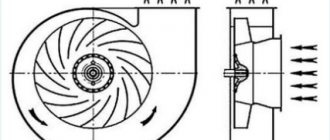
Models of such drives are most often used in home and industrial environments. The power of individual electric motors varies from 4 W to 10 kW, depending on the scope of use it can be small. The main types of devices where this type of electric drive can be used:
- Fans used for industrial purposes.
- Various processing machines.
- Appliances.
- Pump equipment.
Single-phase 220 V electric motors have received widespread use and today solve many household issues. Among motors operating on the basis of electric current, two main categories can be distinguished: single-phase and three-phase.
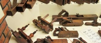
Step-by-step instructions for rewinding an electric motor with your own hands
It is necessary to immediately warn that without special equipment and operating skills, rewinding reels will most likely be a useless task. On the other hand, negative experience is also experience. Understanding the complexity of a process is the best explanation of its cost.
The first stage is dismantling
We present an algorithm of actions for asynchronous machines, it is as follows:
- Disconnect the drive from the network (380 or 220 V).
- We remove the electric motor from the structure where it was installed.
- Remove the rear cooling fan shroud.
- We dismantle the impeller.
- We unscrew the fastening of the end covers, and then remove them. It is advisable to start from the front part; after dismantling it, the rotor will easily “come out” from the rear cover.
- We take out the rotor.
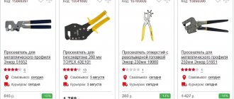
This process can be greatly simplified if you use a special device - a puller. With its help, it is easy to free the motor shaft from a pulley or gear, and also remove the end covers.
Puller for dismantling
We will not provide instructions for disassembling a commutator motor, since it is not particularly different. The structure of an electric machine of this type can be found on our website.
Stage two - removing the winding
The sequence of actions is as follows:
- Using a knife, remove the bandage fasteners and insulating coating from the wire connections. Some instructions recommend recording the wiring diagram, for example, by taking a photograph. There is no particular point in doing this, since this is reference information and finding it out by engine brand is not a problem.
- Using a chisel, knock off the tops of the wires from each end of the stator.
- We release the grooves using a punch of the appropriate diameter.
- We clean the stator from dirt, soot, and impregnation varnish.
Stator freed from the winding
At this stage, we recommend stopping, picking up the housing and taking it to specialists. Independent dismantling will reduce the cost of restoration work. As mentioned above, without special equipment it is quite difficult to rewind reels efficiently. To understand the complexity of the process, we will describe its technology, which will make the choice easier.
Stator rewinding (final phase)
The process consists of the following steps:
- Installation of insulators in each groove (sleeving).
- The thickness of the material and its characteristics are selected from the reference book.
- Winding data is determined by motor brand.
- A special machine is used to wind the required number of turns of loose coils. You can find photos and parameters of homemade manual machines on the Internet, but the quality of their work is quite questionable.
Bulk Winding Machine - The coil groups are placed in the grooves, after which they are tied and connected. These processes are quite complex and are performed manually.
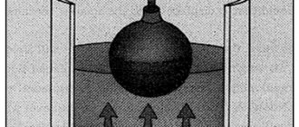
- Impregnation is carried out. To do this, the body is heated to a temperature of 45°C - 55°C and completely immersed in a container with impregnating varnish. It makes no sense to varnish the wires, since in this case there will still be voids.
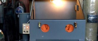
- After impregnation, the body is placed in a special chamber, where drying is carried out at a temperature of 130-135°C.
- Final testing of the coils with an ohmmeter.
- Assembly and test run (if only the body, but also other parts and fasteners were transferred for repair).
If only the body was submitted for restoration, we recommend checking the coils before turning on the motor.
Equipment design
Even though a single-phase asynchronous electric motor has two phases, only one of them works. This is due to the technical design and other important aspects. Currently, manufacturers are paying great attention to increasing the power of all installations and reducing the size. All this happens due to internal parts. Main elements of electric motors:
- stator;
- rotor;
- frame;
- fasteners;
- wiring;
- some models are also equipped with electronic sensors and control systems.
The main advantage of single-phase models remains their simplicity of design. All parts are easy to manufacture in production conditions and quickly assembled. The main disadvantages remain the rather low efficiency.
Principle of operation
The operating principle of a single-phase asynchronous electric motor is to create a pulsating magnetic flux from the flow of electric current through the main stator winding, if we consider the option of starting from an auxiliary turn. Thus, we will consider connecting a single-phase motor to the network using the example of one turn.
Rice. 2. The principle of magnetic flux formation in the stator
As you can see in the figure above, alternating electric current, flowing through a conductor, according to the gimlet rule, creates concentric magnetic fluxes. When the maximum of the sinusoid appears, the magnetic flux will also reach its maximum. However, in a single-phase alternating voltage network, the current changes its direction of movement in a coil with a frequency of 50 Hz. This means that as soon as the curve crosses the x-axis, the current will flow through the winding in the opposite direction and the magnetic flux created by it will receive opposite poles and the direction of the resulting vector:
Rice. 3. Formation of reverse flow
From a physical point of view, both flows are equivalent, so changing them at intervals of 100 times per second will give a zero result when added. The forward magnetic flux will be equal to the reverse one:
Fpr = Fobr
This means that if the rotor of an electric motor is in such a field, it will not rotate. The magnetic flux will change 100 times a minute, and the squirrel-cage rotor will simply hum, remaining in place. However, the situation will change radically if there is an impulse to the initial movement. In this case, slipping will appear, which will lead to constant rotation of the shaft:
Spr = (n1 - n2) / n1, where
- n1 – rotation frequency of the magnetic field of a single-phase electric motor;
- n2 – rotor speed of the asynchronous electric motor;
- S is the slip value of a single-phase induction motor.
When the magnetic flux changes, the direction of rotation and the fields of the stator and rotor of the electric motor will coincide, so the slip will receive a different expression for calculation:
Sobr = (n1 - ( - n2)) / n1, where
The alternating intersection of the rods with magnetic fluxes of different directions will create an EMF in them, which will generate an electric current in the rotor and a response magnetic flux. And it, in turn, will also interact with the stator field of a single-phase electric motor, as shown in the figure below.
Rice. 4. Obtaining EMF in the rotor
As you can see, to connect a three-phase electric motor, you just need to apply voltage to it, but this option will not work with a single-phase one.
To start the motor, a primary impulse is required, which in practice can be obtained by:
- spinning the shaft manually;
- short-term introduction of the trigger coil;
- splitting of the magnetic field by a short-circuited circuit.
Of the above methods, today the first is used only in laboratory experiments; it has fallen out of practical use due to the risk of injury to the operator.
Disadvantages of single-phase current
Theory and practice show that single-phase current cannot independently make a single-phase electric motor move. This is due to the fact that current of this format does not create a magnetic field, so the rotor will not move. To do this, two windings are created in the motors, located at a certain angle to each other. All single-phase 220 V motors used in household appliances are identical. In fact, the disadvantages are minimal, since the use of such equipment models greatly simplifies a person’s life.
The use of alternating current allows you to connect any type of single-phase motor to simple sockets. You can remove them from the compressor and put them on lawn mowers or washing machines.
Connecting a single-phase asynchronous motor
To accelerate an asynchronous motor, it is necessary to create a rotating magnetic field. This is easily handled by a three-phase power supply, where the phases are shifted relative to each other by 120 degrees. But if we are talking about how to connect a single-phase electric motor, then a problem arises: without a phase shift, the shaft will not begin to rotate.
Inside a single-phase asynchronous motor there are two windings: starting and working. If a phase shift is provided in them, the magnetic field will become rotating. And this is the main condition for starting the electric motor. The phases can be shifted by adding resistance (resistor) or an inductive coil. But the most commonly used capacitors are starting and/or running capacitors.
With starting capacity
In most cases, the circuit only includes a starting capacitor. It is active only when the engine is starting. Therefore, the method is good when the launch promises to be difficult, otherwise the shaft will not be able to accelerate due to the small initial torque. After acceleration, the starting capacitor is turned off and operation continues without it.
The connection diagram for a motor with an auxiliary tank is shown in the figure above. To implement it, you will need a relay or at least one button, which you will press for 3 seconds while starting the motor. The auxiliary capacitor, together with the auxiliary winding, is included in the circuit only for a while.
This arrangement provides optimal starting torque if minor AC surges occur during startup. But there is also a drawback - when operating in nominal mode, the technical characteristics drop. This is due to the shape of the magnetic field of the working winding: it is oval, not circular.
With working capacity
If the start is easy, but the work is hard, then instead of a starting capacitor you will need a working capacitor. The connection diagram is shown below. The peculiarity is that the working capacitance, together with the working winding, is constantly connected to the circuit.
The circuit provides good performance when operating in nominal mode.
With both capacitors
A compromise solution is to use auxiliary and working tanks simultaneously. This method is ideal if the AC motor is already started with a load, and the work itself is difficult for it. Look, the diagram below is like two diagrams (with working and auxiliary capacitance) superimposed on each other. When starting, the trigger will be turned on for a few seconds, and the second drive will be active all the time: from start to shutdown.
Capacity calculation
The greatest difficulty for beginners is calculating the capacitance of capacitors. Professionals select them empirically, listening to the engine during startup and operation. This is how they determine whether the drive is suitable or whether they need to look for another one. But with a small error in most cases, the capacity can be calculated as follows:
- For a working drive: 0.7-0.8 µF per 1000 watts of electric motor power;
- For the starting capacitor: 2.5 times more.
Example: you have a 2 kW asynchronous single-phase electric motor. This is 2000 watts. This means that when connecting with a working capacitance, you need to stock up on a 1.4-1.6 µF drive. For the starting one you will need 3.5-4 uF.
Operating principle of the device
Electrical fundamentals and physics are very important to know so that equipment can be started and repaired correctly. Despite its small size, the electric motor is very dangerous for humans if used incorrectly. It is very important to know the power of the equipment for transmitting torque, since it may be insufficient or in excess. The operating principle is as follows:
- A current is supplied to the stator, which creates a magnetic field.
- A magnetic field has its own frequency, amplitude and moment.
- If the rotor does not have a trigger mechanism that will start it, then it will not move even when current is supplied.
- After the trigger is turned on, the rotor begins to move and transmits torque to the shaft.
Since single-phase motors are considered, there are additional start buttons. They turn on to start the rotor, it is recommended to hold the start button for no more than 3 seconds to prevent overheating. The motor itself is equipped with two windings: main and additional. The main one is used to create a two-phase current when the button is turned on. Subsequently, the motor continues to operate as a single-phase motor.
For reliability and protection of equipment, special thermal relays are installed. If the temperature exceeds permissible standards, everything is disconnected from the network.
This is a rather important element that creates safe operating conditions. Fire hazardous situations are eliminated.
Comparison of single-phase and three-phase induction motors
1. Single-phase electric motors are reliable, simple to design, and economical for low power compared to three-phase ones.
2. The electrical power factor of single-phase electric motors is low when compared with three-phase ones.
3. Despite the same size, single-phase electric motors produce about 50% of the output, while three-phase motors produce less.
4. Starting torque is also low for asynchronous motors/single phase induction motors.
5. The efficiency of single-phase electric motors is less than that of three-phase ones.
Single-phase induction electric motors are simple, reliable and cheap for low power. They are generally available for 1 kilowatt power.
Write comments, additions to the article, maybe I missed something. Take a look at the site map, I will be glad if you find anything else useful on my site.
Launch rules
There will be no problems in this aspect. These devices are installed on almost all types of household devices, so a standard household outlet is sufficient. Regardless of what type of electric motor is used, alternating current is always needed. If a low-speed electric motor is used, then other types of energy sources can be used. There are two main types of launch systems:
- Starting is carried out due to additional winding. After the rotor reaches the required speed, it simply turns off and only the main winding works.
- In the second case, a capacitor is used, which is connected to an additional winding. This system works constantly.
All types of 220 V single-phase electric motors considered are interchangeable. That is, the same type of motor is installed on a refrigerator, washing machine, lawn mower, and so on. Currently, during repairs and maintenance, basic safety rules must be observed. In case of any insulation failure, the insulating tape should be replaced with the device turned off.
Connection diagrams
To obtain the basic rotational impulse, various connection schemes can be used. Over time, some of them lost their relevance and were replaced by more progressive ones, so next we will look at the most effective ones, which are still used today.
With starting resistance
Since the resistance of the windings in induction motors has a complex form, the magnetic flux vector can be easily shifted if resistance is added to the starting winding. The presence of an active component will give the required shift angle between the working coils of a single-phase electric motor and the starting coil, from 15° to 50°, which will provide the difference for the initial rotation.
Rice. 5. Circuit with starting resistance
With capacitor start
Unlike the previous method, in a circuit with a capacitor start of an electric motor, a capacitive element is used, which allows you to shift the electrical quantities in the main and starting coils by 90°, providing maximum force.
Rice. 6. Capacitor start circuit
In practice, the starting capacitor along with the additional winding is introduced by the start button simultaneously with the supply of the main power. The start button is designed in such a way that contact Cn is returned by a spring to its original position immediately after the end of the capacitor start.
Split pole
Unlike capacitor motors, this starting method requires the presence of a special design of the stator magnetic circuit. In this case, each pole is divided into two, one of which is equipped with a short-circuited coil that changes the characteristics of the magnetic flux.
Rice. 7. Shaded pole circuit
A significant disadvantage of this method of starting a single-phase electric motor is the constant loss of power and a decrease in the efficiency of the motor. Therefore, it is used only in electric machines up to 100 kW.
Functionality check
Breakdowns happen with any mechanism, and an electric motor is no exception. Breakdowns can most often be determined by external inspection. To carry out diagnostics and more thoroughly study defects, special equipment and instrumentation will be required. Of course, you can diagnose a breakdown by applying a starting current; if the motor does not work, then it’s time to change it. The main types of external signs indicating that repairs are needed:
- There was a burning smell.
- The paint on the body has darkened due to overheating.
- There is damage to the housing.
In some situations, you can fix the breakdown yourself. You need to connect the equipment to direct current; alternating current will not work in this situation. Next, let the engine run for about 10-15 minutes. If during this time it has warmed up, then the reason may be as follows:
- bearing defects: breakdowns, lubricant leakage and other factors.
- high capacitor capacity.
In the second situation, you can turn off the capacitor or lower its capacity, which will lead to a decrease in temperature. Currently, it is recommended to contact specialized workshops for help, since self-repair is not always effective. To make a single-phase 220 V motor low-speed, you will also need tuning on special stands.
Features of repair of commutator drives
This type of electric machine is more likely to experience mechanical failures. For example, brushes worn out or commutator contacts clogged. In such situations, repairs come down to cleaning the contact mechanism or replacing graphite brushes.
Testing the electrical part comes down to checking the resistance of the armature winding. In this case, the probes of the device are applied to two adjacent contacts (lamellas) of the collector, after taking readings, measurements are taken further in a circle.
Checking the armature winding of a commutator motor
The displayed resistance should be approximately the same (taking into account the instrument error). If a serious deviation is observed, then this indicates that there is an interturn short circuit or open circuit, therefore, rewinding is necessary.
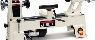
Model overview
Among domestic suppliers and manufacturers of two-phase 220v electric motors, we can highlight the AIR series. They are great for industrial and domestic needs. Design features include the presence of flanges and special mounting feet on the body. They can be included separately or together. The price won't be much different from this. All low- or high-sided variants come with a warranty of approximately 12 months, depending on the brand. Types of cases:
- Aluminum - with a pulley rotation height of up to 90 millimeters.
- Cast iron - with a pulley rotation height of 90 millimeters.
Knowing what a single-phase 220 V motor is intended for, you can immediately choose the appropriate option. The company AACO, which is based in Italy, deserves special attention.
The company sells low-speed and other types of new generation electric motors. When purchasing, you should initially consult with the responsible managers of online stores.
Motor winding data
This is a reference data, so the most reliable way to obtain this information is to consult the appropriate sources. This data can also be provided in the product passport.
You can find advice online that recommends manually counting the turns and measuring the diameter of the wire when rewinding. It's a waste of time. It is much easier and more reliable to find all the necessary information using the engine markings, which will indicate the following parameters:
- rated operating characteristics (voltage, power, current consumption, speed, etc.);
- number of wires for one slot;
- Ø wire (as a rule, insulation is not taken into account in this indicator);
- information on the outer and inner diameter of the stator;
- number of grooves;
- with what step the winding is performed;
- rotor dimensions, etc.
Checking and replacing the starting capacitor
Thermal vacuum treatment increases the service life of the capacitor, eliminating the possibility of internal corrosion of the elements. Clean room, with humidity and air temperature control, high-performance Swiss equipment. We are ready to produce up to 20 pcs. Where other factories employ people, we have automated machines. Faster, better quality, more reliable.
The presence of our own testing laboratories for all types of products allows us to provide additional guarantee to customers regarding the quality of our products. The plant actively participates in thematic exhibitions and regional thematic events. Motor capacitors manufactured by Nykon LLC, K series, are designed for connection to the windings of asynchronous electric motors powered from a single-phase network with a frequency of no more than 60 Hz, as well as for converting three-phase motors to power from a single-phase network.
For safety reasons, all starting capacitors must be used with a discharge resistor. The resistance of the discharge resistor is selected so that after 50 seconds the residual voltage is completely removed from the capacitor.
In cases where the capacitor is used in a series connection with the auxiliary winding of the electric motor, the voltage at the capacitor terminals at operating speed can be significantly higher than the mains voltage. During operation of capacitors, they can be installed directly in physical contact with the electric motor. In this case, when choosing the type of capacitor, it is necessary to take into account that the capacitor will be exposed to elevated temperatures and vibrations - both from the electric motor itself and from other passive elements of various types of devices in which the capacitor will be used.
In the process of selecting the required capacitance and operating voltage, it is necessary to take into account the resonance factor, that is, when the voltage values of the auxiliary winding of the electric motor and capacitor are at the near-resonance point. In this case, the voltage at the terminals of the product increases.
The maximum voltage at the terminals of the starting capacitor should be no more than V, and its capacitance is selected, as a rule, two or more times the capacitance of the working capacitor. To determine the starting capacity Descent. If the engine starts without load, a starting capacitance is not required. To obtain a starting torque close to the nominal one, it is enough to have a starting capacitance determined by the ratio Sp. Fig 1. Capacitors create a phase shift between the currents of the windings, the axes of which are shifted in space.
When starting a capacitor asynchronous motor, both capacitors are turned on, and after it accelerates, one of the capacitors is turned off; this is due to the fact that at rated speed, significantly less capacity is required than at start-up. Used in low power electric drives; at powers above 1 kW it is rarely used due to the significant cost and size of the capacitors. By using this site and any of its services, you confirm your consent to the processing of personal information.
Factory location:. Contacts Buyer Press center About the plant. Thank you for your interest in our Company. Print version. As practice shows, for every watt of electric motor power, about μF is required. Scope of application of capacitors for asynchronous motors Table: Scope of application of capacitors for asynchronous motors working starting Application In circuits of asynchronous electric motors In circuits of asynchronous electric motors Connection type In series with the auxiliary winding of the electric motor In parallel with the working capacitor As a phase-shifting element Purpose Allows to obtain a circular rotating magnetic field necessary for operation of the electric motor Allows you to obtain the magnetic field necessary to increase the starting torque of the electric motor. Turn-on time During the operation of the electric motor At the moment of starting the electric motor There are two main areas of application of capacitors for asynchronous electric motors.
An approximate calculation for this type of connection is made using the following formula: Service. Fig 2. Selection of capacitor installation:. Rated power, kvar. Build a route to the plant from: m.
Rewinding the armature
The process of replacing the winding of a commutator motor is somewhat similar, with the exception of small nuances associated with the design features. For example, the armature is sent for rewinding, not the housing, provided that the problem does not arise with the excitation coils. In addition, there are the following differences:
- For winding, a special machine with a more complex configuration is used.
- Grooving, balancing of the armature (in the final part of the process), as well as its cleaning and grinding are required.
- The manifold is cut using a special milling machine.
The above processes require special equipment; without it, rewinding electric motors is a waste of time.