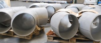
Unlike bent and steeply curved fittings, welded sector bends OST 34 10 419 are not parts, but assembly units. Shaped products DN 125 – 1220 mm are created for the construction of pipelines of groups B and C in nuclear energy.
Bends are made by welding from sectors/half-sectors. Fittings are used to transport media with a nominal pressure below 2.5 MPa at temperatures up to +300°C. We provide competitive prices for pipeline products of our own production in Moscow.
Welded sector bends
Welded sector (segment) bends are used to connect large-diameter pipes with a certain angle of rotation of the flow, operating under low pressure conditions. The angle of rotation of the welded elbow depends on the application and operating conditions of the part. Welded sector bends can be manufactured at different angles, but the most common sector welded bends have an angle of 30°, 45°, 60° and 90°. Today, in almost all construction of pipelines or heating mains, welded sector bends are used. In the figure below, you can see how welded sector bends schematically look:
Welded sector bends:
Welded sector bends are most often manufactured according to two standards: OST 36-21-77 (for oil pipelines) and OST 34 10.752-97 (for water and steam pipelines). Welded sector bends are made from a sheet of steel or pipe by manufacturing cone-shaped rings and then welding them into a bend (elbow). Such bends come from a diameter of 530 mm and above. A distinctive feature of welded bends is the price; as a rule, it is several times lower than the price of steeply curved seamless bends and stamp-welded bends of large diameters, this is due to the simple process of their manufacture.
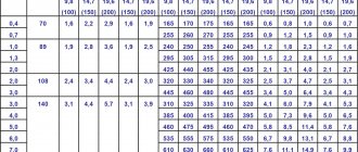
The tables below indicate all types of welded sector bends according to OST 36-21-77 and OST 34 10.752-97 supplied by our company, as well as all the characteristics of these bends:
Bends according to OST 36-21-77
| Dimensions, mm | Conditional pressure Ru MPa | |||||||||||
| Du | Dн | R | L angled bends | N | s | non-aggressive | moderately aggressive | |||||
| sectors | half-sectors with an angle | |||||||||||
| 90° | 60° | 45° | 30° | 22°30’ | 15° | |||||||
| 500 | 530 | 750 | 750 | 432 | 310 | 201 | 260 | 200 | 130 | 7 8 10 12 | 1,6 (16) 2,5 (25) — — | 1,0 (10) — 1,6 (16) 2,5 (25) |
| 600 | 630 | 900 | 900 | 520 | 372 | 241 | 314 | 242 | 157 | 7 10 12 | 1,6 (16) 2,5 (25) — | 1,0 (10) 1,6 (16) 2,5 (25) |
| 800 | 820 | 1200 | 1200 | 694 | 496 | 322 | 424 | 327 | 212 | 8 10 12 14 | 1,6 (16) — 2,5 (25) — | 1,0 (10) 1,6 (16) — 2,5 (25) |
| 1000 | 1020 | 1500 | 1500 | 865 | 620 | 402 | 530 | 410 | 265 | 8 10 12 15 | 1,0 (10) 1,6 (16) — 2,5 (25) | 0,63 (6,3) 1,0 (10) 1,6 (16) — |
| 1200 | 1220 | 1800 | 1800 | 1040 | 745 | 483 | 638 | 493 | 319 | 9 12 15 | 1,0 (10) 1,6 (16) — | 0,63 (6,3) 1,0 (10) 1,6 (16) |
| 1400 | 1420 | 2100 | 2100 | 1210 | 870 | 564 | 744 | 576 | 372 | 10 14 | 1,0 (10) 1,6 (16) | 0,63 (6,3) 1,0 (10) |
In the following table you can see the mass of bends manufactured in accordance with OST 36-21-77:
| Dimensions, mm | Weight, kg | |||||||
| Du | S | angled bends | sectors | half-sectors with an angle | ||||
| 90° | 60° | 45° | 30° | 22°30’ | 15° | |||
| 500 | 7 8 10 12 | 109,1 124,4 154,7 184,7 | 72,7 83,8 102,9 122,9 | 56,0 63,8 79,3 94,6 | 36,2 41,2 51,2 61,0 | 36,0 41,0 50,9 60,7 | 27,8 31,6 39,2 46,7 | 17,9 20,3 25,2 29,9 |
| 600 | 7 10 12 | 155,9 220,9 265,2 | 103,9 147,4 176,0 | 80,1 113,6 135,6 | 51,8 73,3 87,5 | 51,6 73,0 87,1 | 39,8 56,3 67,1 | 25,6 36,2 43,0 |
| 800 | 8 10 12 14 | 309,3 385,5 461,1 535,9 | 206,0 256,7 306,9 356,5 | 159,0 198,0 236,8 275,2 | 102,8 127,9 152,8 177,5 | 102,4 127,5 152,3 177,0 | 79,0 98,4 117,4 136,3 | 50,9 63,3 75,5 87,3 |
| 1000 | 8 10 12 15 | 481,9 600,8 719,1 895,5 | 321,0 400,2 487,8 596,1 | 247,8 308,8 369,4 459,8 | 160,1 199,5 238,6 296,7 | 159,8 199,0 238,0 296,0 | 123,3 153,6 183,6 228,2 | 79,5 98,9 118,1 146,6 |
| 1200 | 9 12 15 | 778,0 1037,2 1288,7 | 518,3 690,8 858,0 | 400,2 531,6 662,1 | 258,6 343,4 427,3 | 258,1 342,7 426,6 | 199,3 264,4 329,0 | 128,5 170,3 211,6 |
| 1400 | 10 14 | 1174,2 1637,9 | 782,2 1090,8 | 603,9 841,9 | 390,3 543,7 | 389,7 542,9 | 300,8 418,8 | 194,0 269,7 |
Below is an example of a symbol for bends according to OST 36-21-77:
Bend 90° , diameter 530 mm, wall thickness 10 mm, made of steel grade 17G1S: Bend 90° 530x10 17G1S OST 36-21-77
Bends according to OST 34.10.752-97
OST 34 10.752-97 has 5 tables, each of which indicates all the characteristics for bends (elbows) of 15°, 30°, 45°, 60° and 90°. We will not describe the characteristics of all bends, but will indicate the characteristics of the most popular bends - bends with an angle of 90°:
| Conditional Pressure Ru | Conditional diameter Dу | Size Attach. Pipes Dн x S | Dн1 | S1 | R | α1 | α2 | φ | a | a1 | b | b1 | C | Weight, kg |
| 2,5 (25) | 100 | 108*4 | 108 | 4 | 305 | 11° 15’ | 22° 30’ | 90° | 144 | 122 | 100 | 100 | 355 | 6,2 |
| 125 | 133*4 | 133 | 320 | 154 | 127 | 370 | 8,1 | |||||||
| 150 | 159*5 | 159 | 5 | 330 | 164 | 132 | 380 | 12,3 | ||||||
| 200 | 219*7 | 219 | 7 | 360 | 188 | 144 | 100 | 100 | 410 | 25,6 | ||||
| 250 | 273*8 | 273 | 8 | 410 | 218 | 159 | 110 | 105 | 460 | 40,9 | ||||
| 300 | 325*8 | 325 | 490 | 260 | 180 | 130 | 115 | 540 | 56,8 | |||||
| 350 | 377*9 | 377 | 9 | 570 | 300 | 200 | 150 | 125 | 620 | 84,3 | ||||
| 400 | 426*10 | 426 | 10* | 640 | 240 | 220 | 170 | 135 | 690 | 118,4 | ||||
| 500 | 530*8 | 530 | 8 | 800 | 424 | 212 | 212 | 106 | 800 | 134,0 | ||||
| 11 | 530 | 318 | 209 | 106 | 103 | 580 | 138,5 | |||||||
| 600 | 630*8 | 630 | (12) | 950 | 504 | 252 | 252 | 126 | 950 | 283,3 | ||||
| 630 | 378 | 239 | 126 | 113 | 680 | 209,4 | ||||||||
| 700 | 720*9 | 720 | 9 | 1080 | 572 | 286 | 286 | 143 | 1080 | 276,4 | ||||
| 11 | 720 | 432 | 266 | 144 | 122 | 770 | 247,6 | |||||||
| 800 | 820*11 | 820 | 1230 | 652 | 326 | 326 | 163 | 1230 | 438,8 | |||||
| 820 | 492 | 296 | 164 | 132 | 870 | 317,7 | ||||||||
| 1000 | 1020*14 | 1020 | 14 | 1350 | 812 | 406 | 406 | 203 | 1530 | 862,5 | ||||
| 1020 | 608 | 304 | 202 | 101 | 1020 | 579,0 | ||||||||
| 1200 | 1220*14 | 1220 | 1830 | 972 | 486 | 486 | 243 | 1830 | 1233,7 | |||||
| (18) | 1220 | 732 | 366 | 244 | 122 | 1220 | 1068,5 | |||||||
| 1,6 (16) | 400 | 426*6 | 426 | 10* | 640 | 340 | 220 | 170 | 135 | 690 | 118,4 | |||
| 500 | 530*8 | 530 | 8 | 530 | 318 | 209 | 106 | 103 | 580 | 100,7 | ||||
| 600 | 630*8 | 630 | (10) | 950 | 504 | 252 | 252 | 126 | 950 | 236,7 | ||||
| 630 | 378 | 239 | 126 | 113 | 680 | 174,6 | ||||||||
| 700 | 720*9 | 720 | 9 | 720 | 432 | 266 | 144 | 122 | 770 | 202,8 | ||||
| 800 | 820*9 | 820 | 1230 | 652 | 326 | 326 | 163 | 1230 | 358,5 | |||||
| 820 | 492 | 296 | 164 | 132 | 870 | 259,9 | ||||||||
| 1000 | 1020*10 | 1020 | 10 | 1530 | 812 | 406 | 406 | 203 | 1530 | 616,3 | ||||
| 1020 | 608 | 304 | 202 | 101 | 1020 | 413,0 | ||||||||
| 1200 | 1220*11 | 1220 | 11 | 1830 | 972 | 486 | 486 | 243 | 1830 | 969,4 | ||||
| 1220 | 732 | 366 | 244 | 122 | 1220 | 651,8 | ||||||||
| 1400 | 1420*14 | 1420 | (14) | 2130 | 1132 | 566 | 566 | 283 | 2130 | 1671,3 | ||||
| 1420 | 852 | 426 | 284 | 142 | 1420 | 1123,8 | ||||||||
| 1600 | 1620*14 | 1620 | (14) | 2430 | 1290 | 644 | 644 | 322 | 2206,2 | |||||
| (18) | 1620 | 966 | 483 | 322 | 161 | 1901,6 |
Below is an example of a symbol for bends according to OST 34 10.752-97:
Bend 90° , diameter 426 mm, wall thickness 12 mm, made of steel grade 09G2S: Bend 90° 426x12 09G2S OST 34.10.752-97
If you need to see the above characteristics for elbows 15°, 30°, 45° or 60°, then you can view them on our website by clicking on OST 34 10.752-97.
All seams of welded elbows are carefully checked for non-destructive testing, as well as destructive testing. Control methods can be different, for example: Radiation flaw detection, ultrasonic flaw detection, magnetic and electromagnetic flaw detection, etc. Therefore, all welded bends supplied by TD Soyuz DSK LLC successfully withstand all the necessary impacts under the correct operating conditions.
Welded sector bends can be made from various types of steel (carbon, low-alloy, high-alloy, corrosion-resistant, heat-resistant and heat-resistant). They are used in pipeline connections for many types of industry, allowing their use according to operating conditions.
Our company supplies welded section bends from various grades of steel, such as: steel 20 and 09G2S (welded steel bends), steel 12x18n10t (welded stainless steel bends), etc. It is possible to manufacture welded sector bends of other diameters, from other grades of steel, according to other regulations documents (TU 102-488-95, etc.), as well as according to the customer’s drawings and sketches.
For all welded sector bends supplied by our company, quality certificates, permission to use, and a certificate of conformity are issued.
If you still have questions related to welded sector bends, you can ask them to our company managers by email [email protected] or by phone +7 (343) 361 2377
Manufactured products: Welded sector bends
Might be interesting
1) Steeply curved bends (seamless according to GOST 17375-01, GOST 30753-01)
2) Stamp-welded bends (TU 102-488-05)
3) Bent bends (TU 51-515-91, OST 36-42-81, GOST 22793-83, etc.)
4) Turned bends (seamless) (according to drawing)
Scope of use of steel bends
Let's consider the main areas in which these products are used:
- plumbing systems;
- heating communications;
- industrial highways for various purposes;
- oil and gas industry;
- chemical industry;
- pumping stations.
Such products are used for wiring communications for any purpose, however, not all of their types are suitable for certain pipelines. For example, for laying main networks, as a rule, steeply curved seamless, stamped-welded, and bent products made of stainless steel, alloyed, and galvanized bends are used. This is due to the fact that such communications have large cross-sectional dimensions and can operate at high pressure in the working environment.
Helpful information! Welded bends are used for various communications. The pressure in such pipelines does not exceed 2.5 MPa. The cross-sectional indicators in such pipelines are usually more than 1000 mm.
For household communications, steeply curved or bent types of bends are an excellent solution. And point products are very popular when installing pipelines at enterprises that produce various mineral fertilizers.
Such a part as a bend can be found on a pipeline of any type and purpose.
As mentioned above, such a product provides rotation of the structure. Bends are used not only in pipelines, but also in communications responsible for cleaning indoor air. The most popular in this case is a galvanized ventilation outlet.
Application area
Sector bends or elbows (industry standard 34-10-752) are used in large-diameter pipelines with low pressure of the transported medium. According to the provisions of the specified industry standard, the main area of use of sector bends is the installation of pipelines for thermal power plants.
Sectional bends (industry standard 36-21) are made from carbon steel. They are also used in pipelines of large diameters with low pressure. These parts are recommended for use in metallurgical, oil, petrochemical, chemical, light and other industries.
Advantages of steel bends
Pipeline fittings are widely used in any installation, and steel turning parts are considered the backbone of any pipeline. Along with tees and transition elements, they play an important role in connecting communications and increasing its strength.
Let's look at the main advantages of these products:
- with the help of these products a smooth rotation of the pipeline structure is made;
- the characteristics of metal bends allow them to be used in difficult operating conditions - they have high strength characteristics and can also be operated at high pressure;
- steel products are resistant to temperature fluctuations;
- the cost of such bends is quite affordable;
- have a long service life when used in aggressive industrial conditions.
The most popular today are models that are curved at an angle of 45 and 90°.
The most popular parts are those with a rotation angle of 45 and 90 degrees.
Materials
In order not to make a mistake when choosing a material, experts advise on operational features, as well as the type of working environment for which it will be used.
The following bends can be found on sale:
- carbon products;
- alloyed parts;
- stainless steel;
- bends are galvanized.
For general purpose communications, parts made from carbon steel are ideal. If the working environment in the system consists of aggressive chemicals, then in this case it is recommended to use stainless or alloyed bends.
Alloy steel products can be used at temperatures from −60 to +40 °C. The pressure they can withstand reaches 7.4 MPa. They are often used when installing pipelines in cold climates, as they have high resistance to corrosion at low temperatures.
Stainless steel bends are used in pipelines that transport hot media (water, steam), as well as chemically active substances with both alkaline and acidic conditions. Stainless steel is highly resistant to the damaging effects of corrosion and is therefore ideal for such purposes.
Today, galvanized bends are quite common. The material for such products is galvanized steel. Galvanized steel products are coated with a protective anti-corrosion layer at the production stage.
Parts made from stainless steel are the most resistant to corrosion and therefore durable
As a rule, this layer is represented by zinc, however, others (chrome, nickel, etc.) can also act as protective elements. The galvanized steel outlet can withstand fairly high pressure and is resistant to aggressive environments.
Is welding of bend to bend allowed?
Group: Forum Participants Messages: 363 Registration: 8.4.2010 From: St. Petersburg User No.: 51288
Group: Forum Participants Messages: 363 Registration: 8.4.2010 From: St. Petersburg User No.: 51288
They helped a lot. I initially believed that this was allowed and, when the builders asked, I answered in the affirmative, and then doubts began to plague me))
Group: Forum Members Messages: 38 Registration: 3.3.2006 User No.: 2281
RULES FOR CONSTRUCTION AND SAFE OPERATION OF TECHNOLOGICAL PIPELINES
6.2.6. The distance from the transverse welded joint to the edge of the support or suspension should provide (if necessary) the possibility of its heat treatment and control. The distance from the fitting or other element with a fillet (T) weld to the beginning of the bent section or transverse weld of the pipeline must be no less than the outer diameter of the pipe, but not less than 50 mm for pipes with an outer diameter of up to 100 mm. For pipes with an outer diameter of 100 mm or more, this distance must be at least 100 mm. The length of the straight section between the welds of two adjacent bends must be at least 100 mm for a nominal diameter of less than 150 mm and 200 mm for a nominal diameter of 150 mm and above. When using steeply curved bends, it is allowed to place welded joints at the beginning of the curved section and weld bends without straight sections to each other.
6.2.7. The distance between adjacent welded joints and the length of the ring inserts when welding them into the pipeline must be at least 100 mm.
Group: Forum Participants Messages: 363 Registration: 8.4.2010 From: St. Petersburg User No.: 51288
Group: Forum Participants Messages: 363 Registration: 8.4.2010 From: St. Petersburg User No.: 51288
Group: Forum Participants Messages: 3846 Registration: 13.2.2008 User No.: 15519
Alas, and Ah. See paragraph 6.2.7. in the link of the previous post, we can give it a ride. (There is no such word as “cylindrical” in the insert!).
Post edited by vadim999
— 15.7.2011, 11:52
Group: Forum Participants Messages: 363 Registration: 8.4.2010 From: St. Petersburg User No.: 51288
It just really goes against common sense.
The insert is needed so that the heat-affected zone does not affect the adjacent seam. But the transition has its own length, and it doesn’t matter what to weld it with to a pipe, or to another transition, there will still be two seams in this segment (usually less than 100 mm), and in order to minimize the seams, it is more logical to weld the fittings to each other.
Group: Forum Participants Messages: 3846 Registration: 13.2.2008 User No.: 15519
It just really goes against common sense.
The insert is needed so that the heat-affected zone does not affect the adjacent seam. But the transition has its own length, and it doesn’t matter what to weld it with to a pipe, or to another transition, there will still be two seams in this segment (usually less than 100 mm), and in order to minimize the seams, it is more logical to weld the fittings to each other.
And if you measure not the length of the center line of the transition, but the length of its generatrix. It will not work?
Group: Forum Participants Messages: 1168 Registration: 5/30/2007 From: Cherkassy User No.: 9054
Group: Forum Participants Messages: 1365 Registration: 1/18/2008 From: Nezhnoburg User No.: 14594
Yes, there are no prohibitions on welding transitions to transitions, or bends to transitions, or bends to bends. There is GOST 16037-80* for pipeline welding. Here you can refer to it. The wall thickness and bevel of the edges of your products are suitable for one of the types of welding specified in this standard (C2 or C17 in your case). And your inspector can only wish you to quickly gain experience.
Post edited by GASPAR
— 15.7.2011, 19:08
Group: Forum Members Messages: 25671 Registration: 12/4/2006 Of: 97 User No.: 5032
Group: Forum Participants Messages: 1365 Registration: 1/18/2008 From: Nezhnoburg User No.: 14594
If all possible pipeline parts are included in GOST, then it will be even cooler than “war and peace”. There are essentially two transitions - sections of pipes and that’s all. This is first of all. Secondly, I designed these types of connections myself many times and built them - there were no comments from any examination or acceptance test. Thirdly, actually, what document prohibits this? That's right - none. Fourthly, why do we need an insert between these parts? An extra joint on a gas pipeline?
Post edited by Gemini
— 16.7.2011, 21:18
source
Last news
Is it possible to directly connect standard piping fittings, such as flanges and elbows, two reducers, a reducer and an elbow? — doubts about this arise among both technological circuit designers and engineers. Are there any technical difficulties with this? Is such a solution permissible under the operating rules? Let's try to figure it out.
Sizes of steel bends
The angles of these products may be different, as well as the diameter sizes, however, all products are subject to certain standards. Standard angles are usually:
- 15°;
- 30°;
- 45°;
- 60°;
- 90°;
- 180°;
The weight of the part can also be different and depends on its diameter. This dependency is shown in the table below.
Table 1
| Du, mm | Weight, kg |
| 820 | 376 |
| 720 | 275 |
| 630 | 219 |
| 530 | 138–153 |
| 426 | 78–97 |
| 377 | 61–75 |
| 325 | 39–56 |
| 273 | 27–35 |
| 219 | 13–20 |
| 159 | 6,1–11 |
| 133 | 3,3–5,7 |
| 114 | 2,2–3,8 |
| 108 | 2,5–3,6 |
| 89 | 2,3 |
The choice of part is made taking into account the size of the pipeline. There are bends of various cross-sections (from 89 to 2000 mm). It is also worth noting that, if necessary, in production you can make an individual order for a rotating element, which will differ in diameter or have a non-standard angle.
Is welding of bend to bend allowed?
Group: Forum Participants Messages: 363 Registration: 8.4.2010 From: St. Petersburg User No.: 51288
Group: Forum Participants Messages: 363 Registration: 8.4.2010 From: St. Petersburg User No.: 51288
They helped a lot. I initially believed that this was allowed and, when the builders asked, I answered in the affirmative, and then doubts began to plague me))
Group: Forum Members Messages: 38 Registration: 3.3.2006 User No.: 2281
RULES FOR CONSTRUCTION AND SAFE OPERATION OF TECHNOLOGICAL PIPELINES
6.2.6. The distance from the transverse welded joint to the edge of the support or suspension should provide (if necessary) the possibility of its heat treatment and control. The distance from the fitting or other element with a fillet (T) weld to the beginning of the bent section or transverse weld of the pipeline must be no less than the outer diameter of the pipe, but not less than 50 mm for pipes with an outer diameter of up to 100 mm. For pipes with an outer diameter of 100 mm or more, this distance must be at least 100 mm. The length of the straight section between the welds of two adjacent bends must be at least 100 mm for a nominal diameter of less than 150 mm and 200 mm for a nominal diameter of 150 mm and above. When using steeply curved bends, it is allowed to place welded joints at the beginning of the curved section and weld bends without straight sections to each other.
6.2.7. The distance between adjacent welded joints and the length of the ring inserts when welding them into the pipeline must be at least 100 mm.
Group: Forum Participants Messages: 363 Registration: 8.4.2010 From: St. Petersburg User No.: 51288
Group: Forum Participants Messages: 363 Registration: 8.4.2010 From: St. Petersburg User No.: 51288
Group: Forum Participants Messages: 3846 Registration: 13.2.2008 User No.: 15519
Alas, and Ah. See paragraph 6.2.7. in the link of the previous post, we can give it a ride. (There is no such word as “cylindrical” in the insert!).
Post edited by vadim999
— 15.7.2011, 11:52
Group: Forum Participants Messages: 363 Registration: 8.4.2010 From: St. Petersburg User No.: 51288
It just really goes against common sense.
The insert is needed so that the heat-affected zone does not affect the adjacent seam. But the transition has its own length, and it doesn’t matter what to weld it with to a pipe, or to another transition, there will still be two seams in this segment (usually less than 100 mm), and in order to minimize the seams, it is more logical to weld the fittings to each other.
Group: Forum Participants Messages: 3846 Registration: 13.2.2008 User No.: 15519
It just really goes against common sense.
The insert is needed so that the heat-affected zone does not affect the adjacent seam. But the transition has its own length, and it doesn’t matter what to weld it with to a pipe, or to another transition, there will still be two seams in this segment (usually less than 100 mm), and in order to minimize the seams, it is more logical to weld the fittings to each other.
And if you measure not the length of the center line of the transition, but the length of its generatrix. It will not work?
Group: Forum Participants Messages: 1168 Registration: 5/30/2007 From: Cherkassy User No.: 9054
Group: Forum Participants Messages: 1365 Registration: 1/18/2008 From: Nezhnoburg User No.: 14594
Yes, there are no prohibitions on welding transitions to transitions, or bends to transitions, or bends to bends. There is GOST 16037-80* for pipeline welding. Here you can refer to it. The wall thickness and bevel of the edges of your products are suitable for one of the types of welding specified in this standard (C2 or C17 in your case). And your inspector can only wish you to quickly gain experience.
Post edited by GASPAR
— 15.7.2011, 19:08
Group: Forum Members Messages: 25671 Registration: 12/4/2006 Of: 97 User No.: 5032
Group: Forum Participants Messages: 1365 Registration: 1/18/2008 From: Nezhnoburg User No.: 14594
If all possible pipeline parts are included in GOST, then it will be even cooler than “war and peace”. There are essentially two transitions - sections of pipes and that’s all. This is first of all. Secondly, I designed these types of connections myself many times and built them - there were no comments from any examination or acceptance test. Thirdly, actually, what document prohibits this? That's right - none. Fourthly, why do we need an insert between these parts? An extra joint on a gas pipeline?
Post edited by Gemini
— 16.7.2011, 21:18
source
