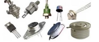
In reality, we can find different types of semiconducting switches. They are used to connect power to a load or to uniformly control an electrostatic field and electric current.
Among such devices we can distinguish triacs. Most often they are used in illumination control, household electrical appliances, and industrial generators.
In this article we will present you with two ways to check the suitability of a triac and thyristor: with a multimeter and with a home-made device.
Purpose and device
Triacs are a semi-conducting switch that can be opened by a current signal through the leading electorate.
In order to close the triacs, it is necessary to break the current in the circuit or apply the opposite voltage.
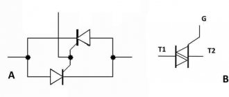
The principle of its operation is identical to the operation of a thyristor. The only difference is that triacs consist of two thyristors that are connected and operate simultaneously.
You can see the definition on the graph below.
According to their designation, they are usually used in radio relay mode - to put it simply in terms of “connection” and “turndown”, such relays are considered semiconducting.
Unlike the electro-mechanized one, it works much faster, there is no communication and, as a result, greater stability and reliability.
The main need for long-term use is guaranteed temperature conditions and saturation.
Circuit for testing thyristors
Every radio amateur should have his own small laboratory. But what to do if you don’t have enough money even for a simple soldering station? This article will talk about how to make a simple device for testing thyristors from available radio elements, which will be added to your collection of useful devices for a radio amateur. Now you will know for sure whether your thyristor is broken or is still alive.
Circuit for testing thyristors
The thyristor belongs to the diode class. You can check it with a multimeter, but if your hands grow from the right place, then of course it’s easier to assemble a device for testing. And here is the diagram:
The scheme consists of:
- a transformer that gives us 5-10 Volts at the output
— diode D226, whatever was at hand. You can use any low-power one.
- electrolytic capacitor 1000 uF x 25 Volts
- toggle switch (S1) with three positions, one of which is neutral (N)
— return button (S2)
- 47 Ohm resistor
- 6.3 Volt incandescent light bulb
Assembly and description
So, let's start with the fact that we need foil PCB. I got some textolite from my stash that was not the first freshness. In order not to worry about wiring elements, etching the board and other various hemorrhoids, for simple circuits I stupidly cut squares and make a simple homemade board. Believe me, this is much faster if you don’t have ready-made Chinese breadboards at hand. To do this, I take an iron file, an iron ruler and scratch out shallow grooves:
If only there was no copper between the squares. Some people manage to make special sharpening points from an iron file, but I don’t like them because they quickly become dull and have to be sharpened.
Next, the whole thing needs to be sanded with fine sandpaper:
The next step is to select a transformer. We select the transformer in such a way that it produces an alternating voltage of any value from 5 to 10 Volts. My transformer produces 12 volts at the output of the secondary winding. I had to unwind half the turns from the secondary winding. Now it produces 6 Volts. For those who don’t know how a transformer works, you can read this article. We make holes for the transformer, mount it on the edge of our homemade printed circuit board and draw out its terminals from the secondary winding onto squares. In order to tin a square, we just need to rosin it a little and add a drop of solder:
This is roughly what the transformer looks like on the board:
And here is the completed structure assembled. All that remains is to find a suitable housing for it.
How to test thyristors
The scheme works as follows:
1)We connect the thyristor T1 being tested to the wires of the circuit.
2)Switch the toggle switch S1 with the neutral position to the “~” icon, press the S2 button.
3)The light comes on when pressed and goes out when released.
Thus, we tested the thyristor on alternating current.
4)Next, set the toggle switch S1 to the “=” position
5)We press the S2 button, the light comes on, we release the S2 button, the light still continues to light.
So we tested the thyristor at direct current.
If all operations were successful, then our thyristor is in perfect health.
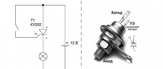
And here is the video for those who are too lazy to read the above text. Here I checked the KU202N thyristor.
My dear readers, read on)) I posted an article about LED, you probably didn’t even know so much about it!
Verification methods
To study the deterioration of the electronic layout, it is necessary to check its components one by one.
First you need to focus on the power circuits, more specifically each of the semiconducting switches. To check the triac and thyristor, you should use one of the methods:
- multimeter;
- battery with light bulb;
- at the stand.
For research, it is necessary to disconnect the component, since during the analysis of various elements of electronic models for suitability, without removing them from the device, there is a risk of inaccurate diagnosis.
For example, say, you noticed a short circuit not of the component that is being diagnosed, but of the one associated with it in the chain synchronously.
Under any conditions, you have the opportunity to diagnose triacs and thyristors for stability without desoldering, and in case of a malfunction, remove them and do the calculations again.
Breakdown test
Testing a thyristor begins with determining the breakdown. It is recommended to start with preliminary testing, which involves measuring the resistance between the two outputs “A” and “K”, “K” and “UE”. The action algorithm has the following features:
- A multimeter is used for testing. It is turned on in the “dialing” mode, and indicators are taken between the two terminals “UE” and “K”. If the device is in good technical condition, then the readings taken will be in the range from 40 Ohms to 0.55 kOhms. A low value may indicate some problems with the device.
- Next, it is recommended to change the position of the probes, and the process is repeated. The taken indicators must correspond to those obtained in the first case.
- The next step is to measure the resistance between terminals “K” and “A”. In this case, the resistance indicator should tend to infinity. The value may vary depending on the polarity of the measuring device. A low indicator indicates that there is a breakdown in the transition. For a more accurate result, it is recommended to desolder the device being tested.
Using a multimeter
If you want to check triacs for penetration using a tester, you need to change the device system to acoustic mode.
The standard location of the transceiver can be seen in the image below. A1 and A2 are electrical power terminals, thanks to which current passes to the load, and G is the main electrode.
Since the transceiver tends to vary, it is necessary to study it in the description of the triac.
In order to check a part for penetration, it is necessary to touch terminals A1 and A2 with probes; if the part is working properly, “1” or 0L will be indicated on the screen; if there is a penetration, a value close to 0.
In cases where there is no short circuit between terminals A1 and A2, it is necessary to examine the main electrode.
First, you need to touch some power terminal and the main electrode with the probes; the values should be low 80-200.
If you want to check whether a triac can open, you need to short-circuit its main electrode with one of the multimeter leads, thus applying current to it.
You can see instructions for checking using the example of a thyristor and triac below.
After removing the voltage from the main electrode, the triacs can be closed. Due to the fact that at least the smallest current must flow in order to maintain conducting conditions.
Similar properties may exist in methods that we will consider further.
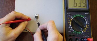
Checking with a multimeter
This is the easiest option to check. In this method, the anode and contacts of the UE are connected to a measuring device (multimeter). The role of a constant current source here is played by the batteries of the multimeter. The indicator is arrows or digital indicators.
What you need to check a thyristor with a multimeter:
- Hook the black probe with a minus to the cathode.
- Hook up the red probe with a plus to the anode.
- Connect one end of the switch to the red probe connector.
- Set up a multimeter to measure resistance not exceeding 2 thousand ohms.
- Quickly turn the switch on and off.
- If the current flow is maintained, then everything is fine with the thyristor. To turn it off, simply disconnect the voltage from one of the electrodes (anode or cathode).
- If there is no conductivity retention , you need to swap the probes and do everything from the very beginning.
- If throwing the probes does not help , then the thyristor is faulty.
To check the thyristor without desoldering, you need to disconnect the UE from the circuit circuit. Next you need to do all the steps described above.
The role of a constant current source here is played by the batteries of the multimeter, and arrows or digital indicators are used as an indicator
Using a battery with a light bulb
In this way, you can check triacs in cases where you don’t have a multimeter, just using a light bulb. You can see the verification model for this method below.
In cases of testing a triac with a battery and a light bulb, it is necessary to remove resistor R1 from the chain. To do this, you need to use 3 alternately connected AA batteries or a crown.
In cases of assembling a portable tester according to this scheme, you have the opportunity to mount a button without focusing with the contacts shown on the model.
Provided that you are not going to make this device, you need to briefly touch the main electrode with the wire, as you already saw in the multimeter method.
Other verification options
The thyristor can also be checked using a tester. To do this you will need a tester, a six to ten volt battery and wiring.
To check the device with a tester, you need to follow the following scheme:
- Checking the thyristor using an ohmmeter Turn on the tester between the cathode and anode: it should show “infinity”, because the thyristor is in a state of low conductivity.
- Connect the battery between the UE and the cathode. The resistance on the tester should drop, as conductivity has appeared.
- If there is no power supply at all , then the device does not work properly.
- If the power supply is constant, at any voltage to the electrodes , then in this case there is something wrong with the thyristor.
Read also: How to make a helicopter from a chainsaw
You can also check the thyristor using an ohmmeter. This method is similar to checking with a multimeter and tester. Required:
- Connect the plus of the ohmmeter to the anode, and the minus to the cathode. The ohmmeter probe should show high resistance.
- Close the output of the anode and the UE , the resistance on the ohmmeter sensor should drop sharply.
That's basically all the instructions for checking. If, after these steps, you disconnect the UE from the anode, but do not break the connection between the anode and the ohmmeter, the device sensor should show low resistance (this occurs if the anode current is greater than the holding current).
There is also another way to check a thyristor using ohmmeters; for this you will need an additional ohmmeter. You need to connect the positive terminal of one ohmmeter to the anode; the resistance at this moment should show high. Next follows, also the positive terminal, but of a different ohmmeter, quickly connect and disconnect from the control electrode (CE), at this moment the resistance of the first ohmmeter will sharply decrease.
\main\r.l. designs\ miscellaneous\…A simple tester for thyristors and triacs
This article presents a simple device that requires very few parts to create. With its help, you can quickly check the performance of thyristors and triacs.
General provisions
A single transistor can be checked for function using a simple analog ohmmeter. Testing a thyristor or triac is somewhat more difficult. Here is a description of the device circuit, with which you can check and evaluate the main parameters of both thyristors and triacs. Before we begin to describe the tester’s circuit, let’s briefly consider what a thyristor and triac are.
Thyristor is a controlled diode. No current flows in the blocking direction (as through a conventional diode), since at the cathode (marked in the diagrams with an arrowhead), relative to the anode, the voltage has a positive sign. We change the polarity of the voltage applied to the thyristor (plus - to the anode, minus - to the cathode), but it does not even think of opening, unlike the diode, the thyristor is still closed, locked. It is now necessary to apply the opening voltage (which, in turn, will cause an opening current) to the control electrode, and the thyristor instantly opens (the current increases very quickly, has the character of a shock, breakdown). Now, even if you remove the control current from the control electrode circuit, the thyristor will remain in a conducting state until the current flowing through it decreases to a value less than a certain value, called the closing current or interruption current: the thyristor will close. Now the thyristor can only be opened by a new portion of current in the control electrode circuit.
A triac is nothing more than a dual thyristor: two thyristors connected in parallel to each other, only “towards” and with one common control electrode, allowing control of the current(s) flowing in both directions (alternating current). At the required time, a current pulse is applied to the control electrode of the triac and the triac opens. When the (alternating) current decreases, passes through zero, and then changes its polarity, the triac automatically closes. Now, only the next current pulse in the control electrode circuit will open the triac.
Scheme
The tester circuit presented here allows you to test only the above-mentioned functions of thyristors and triacs. If switch S1 is in the position indicated in the diagram in Fig. 1, then capacitor C2 is charged through resistor R1 and diode D2 to a voltage close to the voltage of the power battery. Capacitor C1 is discharged, since diode D1 does not conduct current in this direction and is locked. If the thyristor is connected as indicated in the diagram (Fig. 1), then LEDs D4 and D6 will not light up. If you now briefly press the ST2 button, a control current will flow in the thyristor control electrode circuit through resistor R5, which will lead to the opening of the thyristor. LED D4 will light up. LED D6 will remain off since diode D5 is turned on in the non-conducting direction. If you now briefly turn off S1 (move the switch to the adjacent “idle” position) in order to move it to another position (to change the polarity, for example), D4 will immediately go out. By briefly pressing the ST2 button, we again supply a control pulse from the charged capacitor C2 through resistor R5 to the control electrode of the thyristor. This pulse should now not lead to the opening of the thyristor, since the latter is connected to the power source in a non-conducting (blocking thyristor) direction (due to a change in polarity).
The behavior of the triac, in this case, differs from the behavior of the thyristor: the triac, in this case, will open and conduct current. Depending on the polarity of the supply voltage, the triac will open when you press the ST2 or ST1 buttons. Of course, after changing the polarity of the supply voltage, you should wait a little so that the corresponding capacitors have time to charge, and only then press the buttons. C2 is charged only in the position of switch S1 indicated in the diagram (Fig. 1), C1 is charged only in its lower position according to the diagram.
Design
In accordance with the circuit diagram, place the device parts on the circuit board. There are no installation features, since there are no sensitive elements (to interference, etc.). The design is made in such a way that it fits together with the battery in a small case. Three terminals for connecting the tested thyristors or triacs are made of flexible insulated wire using clamps (for example, alligator clips).
How to check thyristors and triacs with a tester and multimeter?
- Connecting electrical equipment through an optocoupler using a control thyristor allows you to control certain processes on the computer motherboard, as well as protect it from overloads, which can lead to disastrous consequences. In this case, it serves as a kind of fuse that turns off the system at the right time.
- In power regulators it is included in the desired branch of the rectifier. By changing the engine power pulses, it adjusts the power supply intervals for stable power at low engine speeds.
- Triacs are often used in power regulators for inductive loads, where they control frequency ranges and more.
- The thyristor volume regulator stabilizes voltage drops that occur during the operation of music centers and other loads that require stabilization of certain modes.
- Thyristor-based fan stabilizers regulate functional characteristics not only by eliminating overheating, but also by maintaining the required number of revolutions.