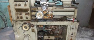
2N112 tabletop drilling machine. Purpose and scope
2N112 desktop drilling machine is designed for drilling holes and cutting threads in small parts made of cast iron, steel, non-ferrous alloys and non-metallic materials in industrial enterprises, repair shops and household workshops.
The drilling depth is measured using a flat scale or stop.
The original design of the belt drive tension allows you to quickly change the position of the belt on the pulleys to obtain the desired cutting speed.
Using a stand to install the 2N112 makes it possible to drill the ends of long parts, such as shafts. The shaft diameter is up to one hundred and twenty millimeters, the length is up to a thousand millimeters.
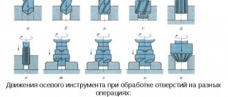
2N112 drilling machine allows you to perform the following operations:
- drilling
- countersinking
- deployment
- reaming
- thread cutting
The spindle of the 2N112 receives 7 rotation speeds from 4-speed drive pulleys, which provides a choice of cutting speeds in the range from 500 to 4000 rpm.
The end of the spindle is an external shortened Morse taper KM2, designation B18 according to GOST 9953 (Shortened tool tapers) - shortened cone: D = 17.780 mm, cone length 37.0 mm.
The shortened cone B18 corresponds to a three-jaw drill chuck of the 16th standard size in accordance with GOST 8522 (Three-jaw drill chucks) with a clamping range from 3 to 16 mm.
An example of a symbol for a 3-jaw drill chuck, size 16, with a connecting conical hole B18:
Cartridge 16-B18 GOST 8522-79
Main technical characteristics of the tabletop drilling machine 2N112
Developer: Molodechno Machine Tool Plant MSZ.
Manufacturer - Training and production workshops of the Perm Mechanical College named after N.G. Slavyanova.
The machine parameters correspond to TU2-024-734 dated March 2, 1967 and GOST 8-53.
- Maximum drilling diameter: Ø 12 mm
- Maximum drilling depth: 100 mm
- Maximum height of the workpiece installed on the work table: 420 mm
- Spindle speed limits per minute - (7 steps) 500..4000 rpm
- Spindle end - B18 external shortened Morse taper 2 according to GOST 9953
- Standard drill chuck - Chuck 16-B18 GOST 8522-79, clamping range 3..16 mm
- Electric motor power: 0.6 kW
- Machine weight: 120 kg
Morse cone instrumental shortened
Tool taper - Morse taper is one of the most widely used tool mounts.
It was proposed by Stephen A. Morse around 1864. The Morse taper is divided into eight sizes - from KM0 to KM7 (in English: MT0-MT7, in German: MK0-MK7).
Morse taper standards: GOST 25557 (Tool cones. Main dimensions), ISO 296, DIN 228. Cones made according to inch and metric standards are interchangeable in everything except the shank thread.
For many applications, the length of the Morse cone turned out to be excessive. Therefore, a standard was introduced for nine standard sizes of shortened Morse cones (B7, B10, B12, B16, B18, B22, B24, B32, B45), these dimensions were obtained by removing the thicker part of the cone. The number in the designation of a short cone is the diameter of the thick part of the cone in mm.
Russian standard for shortened cones GOST 9953
Tool cones are shortened.
Russian standard for drill chucks GOST 8522
Three-jaw drill chucks.
- B7 - Morse cone KM0 , D = 7.067 mm;
- B10 - Morse cone KM1 , D = 10.094 mm. Cartridge 4-B10 (0.5÷4 mm);
- B12 - Morse cone KM1 , D = 12.065 mm. Cartridge 6-B12 (0.5÷6 mm), Cartridge 8-B12 (1÷8 mm);
- B16 - Morse cone KM2 , D = 15.733 mm. Cartridge 10-B16 (1÷10 mm), Cartridge 13-B16 (1÷13 mm);
- B18 - Morse cone KM2 , D = 17.780 mm. Cartridge 16-B18 (3÷16 mm);
- B22 - Morse cone KM3 , D = 21.793 mm. Cartridge 20-B22 (5÷20 mm);
- B24 - Morse cone KM3 , D = 23.825 mm;
- B32 - Morse cone KM4 , D = 31.267 mm;
- B45 - Morse cone KM5 , D = 44.399 mm.
Where D is the diameter of the cone in the main plane.
Electrical equipment and electrical circuit of the drilling machine 2M112
Power supply of the drilling machine 2m112 ~380 or ~220 Volts.
Machines manufactured for industrial enterprises and educational institutions have a supply voltage of ~380 V, for mobile workshops - ~220 V. Local lighting has a safe voltage of ~24 V.
All electrical equipment of the machine: switches, transformer, fuses are placed under the work table plate.
Technical characteristics of the electric drive
- Type of spindle drive electric motor - AIR714U3 or 4A71A4U3
- Electric motor – asynchronous three-phase, with a squirrel-cage rotor, height of the axis of rotation 71 mm, weight 8.4 kg
- Spindle drive electric motor power – 0.55 kW
- Spindle drive electric motor speed – 1370 rpm
Initial start-up and instructions for installation and operation
When installing, you must first connect the machine (cooling unit) to the general grounding system using a special bolt located on the machine plate (on the machine of the cooling unit tank).
The supply wires are inserted by the customer through the hole located on the back of the machine plate (on the casing of the cooling unit control panel).
The OSZR (coolant) device is connected autonomously to the supply circuit.
The machine (cooling unit) is connected to the power supply using switch Q1.
First, it is necessary to test run the machine at idle, at all speeds sequentially, starting with the lowest spindle speed. During the first period after starting the machine, it is not recommended to work at maximum spindle speed.
Protection
The stack's electrical equipment is protected from short circuits and overloads by fuses F1, F2, F3.
To prevent self-starting of the electric motor, zero protection is applied using contacts of magnetic starters K1 and K2.
Instructions for servicing the electrical equipment of the machine
Electrical equipment was installed using wires of the following colors:
- power circuits - black
- control circuits - red
To ensure long-term and trouble-free operation of the machine, it is necessary to regularly clean the electric motor, starting and protective equipment from dust, and contacts from carbon deposits; Tighten connections between drives and equipment as necessary.
Electrical diagram of a drilling machine 2m112 at 380V
List of elements for the electrical diagram
- Q1 – Switch PKU3-154I-2037U3 TU 16-526.047-74
- S1 – Switch KE201U3 used. 5 red “P” TU 16-642.015-84
- S2, S3 – Switch KE181U3 used. 2 black “P” TU 16-642.015-84
- E1 – Lamp NKP03-60-0.04UH4 TU 16.876.184-86. Lamp M 024-40 GOST 1182-77
- Ml – Engine AIR 71 A4U3, 380 V, 50 Hz TU 16-525.564-84 or 4A71A4U3 GOST 19523-81
- F1, F2, F3 – Fuse PRS-6U3-P with fuse link PVD1-6U3 TU 16-522.112-74
- K1, K2 – Starter PME-041U4 (380 V, 50 Hz) OST 16.0.536.001-72
- T, Q2, F4 – Device OSZR-0.04-83UHL3 TU 16-6/1 041-84 (coolant)
It is possible to replace components without compromising the quality of the machine.
Electrical diagram of a drilling machine 2m112 at 220V
Control panel for drilling machine 2m112
Installation of the electrical circuit of a drilling machine 2m112
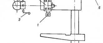
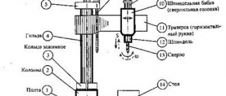
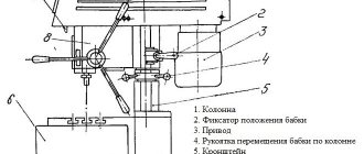
Spindle head of drilling machine 2N112
Spindle head of drilling machine 2n112
Spindle head of drilling machine 2n112
Device Features
Despite the relatively small size and low power of the 2m112 product, frequent and long-term operation of the unit is allowed. High performance of the machine is achieved through simple design solutions that ensure greater operating efficiency of the unit.
The main parts of the machine are the spindle head, which moves using a separate device in the vertical direction along the column. It is fixed on it with a special device that acts as a clamp. The electric motor transmits torque to a system of pulleys, which, in turn, are connected to the chuck through a shaft. The pulley system provides different power and rotation speed of the chuck. A special casing covers the pulley system and the entire drive. The slab serves as a support for the column. The upper part of the stove serves as a work table.
Technical characteristics of the machine 2N112
| Parameter name | 2M112 | 2N112 | 2N115pm |
| Basic machine parameters | |||
| Largest nominal drilling diameter, mm | 12 | 12 | 15 |
| The smallest and largest distance from the end of the spindle to the table | 0…400 | 70..420 | 70..520 |
| Distance from the axis of the vertical spindle to the rack guides (overhang), mm | 190 | 160 | 160 |
| Desktop | |||
| Width of the working surface of the table, mm | 250 x 250 | 250 x 250 | 250 x 250 |
| Number of T-slots | 3 | 3 | 3 |
| Spindle | |||
| Maximum movement of the spindle (drilling) head along the column, mm | 250 | 350 | |
| Spindle sleeve stroke, mm | 100 | 100 | 100 |
| Spindle speed, rpm | 450, 800, 1400, 2500, 4500 | 500, 710, 1000, 1400, 2000, 2800, 4000 | 500, 710, 1000, 1400, 2000, 2800, 4000 |
| Number of spindle speeds | 5 | 7 | 7 |
| Spindle taper | Morse B18 | Morse B18 | Morse B18 |
| Drive unit | |||
| Main motion drive electric motor, kW (rpm) | 0,55 | 0,6 (1350) | 0,8 (1350) |
| Dimensions and weight of the machine | |||
| Machine dimensions (length width height), mm | 795 x 370 x 950 | 785 x 465 x 795 | 785 x 465 x 895 |
| Machine weight, kg | 120 | 120 | 130 |
- Barun V.A. Working on drilling machines, 1963
- Vinnikov I.Z., Frenkel M.I. Driller, 1971
- Vinnikov I.Z. Drilling machines and work on them, 1988
- Loskutov V.V Drilling and boring machines, 1981
- Panov F.S. Working on CNC machines, 1984
- Popov V.M., Gladilina I.I. Driller, 1958
- Sysoev V.I. Handbook for a Young Driller, 1962
Bibliography
Related Links. Additional Information
- Classification and main characteristics of drilling-milling-boring group of machines
- Selecting the right metalworking machine
- Machine repair technology
- Methodology for checking and testing drilling machines for accuracy and rigidity
- Directory of drilling machines
- Manufacturers of drilling machines in Russia
Home About the company News Articles Price list Contacts Reference information Interesting video KPO woodworking machines Manufacturers
Kinematic diagram of a table-top vertical drilling machine 2M112.
The kinematic diagram of the 2M112 vertical drilling machine is shown in the following figure:
The kinematic diagram of the 2M112 table-top vertical drilling machine with good resolution and quality is given in the 2M112 machine passport, a link to which was given above.
| < Previous | Next > |
Related materials:
- ELL 12XXX. Electric drive. Passport, Manual, Instructions, Description, Characteristics.
- ELL 4XXX. Electric drive. Passport, Manual, Instructions, Description, Characteristics.
- Drawing. 2A135. Vertical drilling machine. Kinematic scheme
- Drawing. IR800PMF4. Horizontal boring machine. Gearbox. Kinematic diagram
- Drawing. VSZ-64M. Vertical milling machine. Kinematic diagram
The following materials:
- 16K20RF3. CNC screw-cutting lathe 2Р22. Passport, Characteristics, Diagram, Manual
- 16A20F3. CNC screw-cutting lathe NTs-31. Electrical automation board diagram
- 16A20F3S39. CNC screw-cutting lathe NTs-31. Electrical automation board diagram
- 24K40AF4-01. CNC coordinate machine TNC-145. Passport, Characteristics, Diagram, Manual
- 24K40SF4-01. CNC coordinate machine TNC-145. Passport, Characteristics, Diagram, Manual
Previous materials:
- 16K20RF3S32. CNC screw-cutting lathe 2Р22. Passport, Characteristics, Diagram, Manual
- 16K25. Screw-cutting lathe. Passport, Specifications, Scheme, Manual, Drawings
- 16K20P. Screw-cutting lathe. Passport, Specifications, Scheme, Manual, Drawings
- 16K20G. Screw-cutting lathe. Passport, Specifications, Scheme, Manual, Drawings
- 2N135 vertical drilling machine: Passport, Characteristics, Diagram, Manual