Information about the manufacturer of the vertical drilling machine 2Р135Ф2
The manufacturer of drilling machines models 2Р135Ф2, 2Р118Ф2, 2Н125, 2Н135, 2Н150, 2Г175 is the Sterlitamak Machine Tool Plant , founded in 1941.
The history of the Sterlitamak Machine Tool Plant begins on July 3, 1941, when the evacuation of the Odessa Machine Tool Plant to the city of Sterlitamak began.
Already on October 11, 1941, the Sterlitamak Machine Tool Plant began producing special modular machines for the defense industry.
Currently, the plant produces metalworking equipment, including CNC lathes and milling machines, multifunctional machining centers.
Products of the Sterlitamak Machine Tool Plant
- 2135
— universal vertical drilling machine, Ø 35 - 2A125
- universal vertical drilling machine, Ø 25 - 2A135
- universal vertical drilling machine, Ø 35 - 2A150
- universal vertical drilling machine, Ø 50 - 2G175
- universal vertical drilling machine, Ø 75 - 2N125
- universal vertical drilling machine, Ø 25 - 2N135
- universal vertical drilling machine, Ø 35 - 2N150
- universal vertical drilling machine, Ø 50 - 2R135F2
- CNC vertical drilling machine, Ø 35 - 2С50
- universal vertical drilling machine, Ø 50 - 2S125, 2S125-1 (2S125-01), 2S125-04
- universal vertical drilling machine, Ø 25 - 2S132, 2S132K
- universal vertical drilling machine, Ø 32 - 2С150ПМФ4
- vertical drilling-milling-boring machine with CNC and ASI, 500 x 1000 - 2С550А
– radial drilling machine, Ø 36 - 400V
- vertical drilling-milling-boring machine with CNC and ASI, 400 x 900 - 500V (STC F55)
- vertical milling center, 630 x 1200 - SF-16, SF-16-02, SF-16-05
- tabletop milling and drilling machine, Ø 16 - SRB50
– radial drilling machine, Ø 3..50
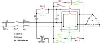
Drawing. Kinematic diagram of the machine 2Р135Ф2
This drawing was made in the KOMPAS CAD system and is a “Kinematic diagram of the 2R135F2 machine”. This file will be useful to students studying the subject “Metal-cutting machines” for writing a diploma or course project.Download for free “Drawing. The kinematic diagram of the 2Р135Ф2 machine "in excellent quality can be found at the link below:
download a free program for viewing and printing this drawing from the link below:
view additional information on “Machine 6Р135Ф2 ” at the link below:
Search the site on the topic “Machine 6Р135Ф2”
You can view other drawings related to the subject of the site using the link below:
Search the site on the topic “Drawings”
| Next > |
The following materials:
- Drawing. 16K20F3. CNC screw-cutting lathe. Kinematic diagram This drawing was made in the CAD system KOMPAS and is the “Kinematic diagram of a 16K20F3 screw-cutting lathe.” This file will be useful to students studying the subject “Metal-cutting machines” for writing a diploma or course project. Download free “Drawing. 16K20F3. Screw-cutting lathe…
">Drawing. 16K20F3. CNC screw-cutting lathe. Kinematic diagram
- Drawing. Kinematic diagram of the gearbox of the machine 16K20 This drawing was made in the CAD system KOMPAS and is the “Kinematic diagram of the gearbox of the machine 16K20”. This file will be useful to students studying the subject “Metal-cutting machines” for writing a diploma or course project. Download free “Drawing. Kinematic diagram of the gearbox of the machine 16K20...
">Drawing. 16K20. Screw-cutting lathe. Kinematic diagram of the gearbox
- Drawing. Kinematic diagram of the 5V12 machine This drawing was made in the KOMPAS CAD system and is the “Kinematic diagram of the 5V12 machine”. This file will be useful to students studying the subject “Metal-cutting machines” for writing a diploma or course project. Download free “Drawing. Kinematic diagram of the 5V12 machine" in excellent quality can be found at the link...
">Drawing. 5B12. Gear shaping machine. Kinematic diagram
- Drawing. Kinematic diagram of the 6M82 machine This drawing was made in the KOMPAS CAD system and is the “Kinematic diagram of the 6M82 machine”. This file will be useful to students studying the subject “Metal-cutting machines” for writing a diploma or course project. Download free “Drawing. Kinematic diagram of the 6M82 machine" in excellent quality can be found at the link located...
">Drawing. 6M82. Horizontal milling machine. Kinematic diagram
- Drawing. Kinematic diagram of the machine 6N13F3-2 This drawing was made in the CAD system KOMPAS and is the “Kinematic diagram of the machine 6N13F3-2”. This file will be useful to students studying the subject “Metal-cutting machines” for writing a diploma or course project. Download free “Drawing. Kinematic diagram of the machine 6N13F3-2" in excellent quality can be found at the link…
">Drawing. 6N13F3-2. Multi-purpose CNC milling machine. Kinematic diagram
Previous materials:
- Drawing. Lead screw of the upper part of the support of a 1K62 screw-cutting lathe. This drawing was made in the CAD system KOMPAS and is a “Drawing. Lead screw of the upper part of the support of a 1K62 screw-cutting lathe.” This file will be useful to students studying the subject “Metal-cutting machines” for writing a diploma or course project. Download free “Drawing. Chassis…
">Drawing. 1K62. Screw-cutting lathe. Caliper top lead screw
- Drawing. Kinematic diagram of a vertical milling machine 6A54 This drawing was made in the CAD system KOMPAS and is the “Kinematic diagram of a vertical milling machine 6A54”. This file will be useful to students studying the subject “Metal-cutting machines” for writing a diploma or course project. Download free “Drawing. Kinematic diagram of vertical milling...
">Drawing. 6A54. Vertical milling machine. Kinematic diagram
- Drawing. Gearbox of screw-cutting lathe 16K30F3. Development This drawing was made in the CAD system KOMPAS and is a “Speed box of a 16K30F3 screw-cutting lathe. Scan". This file will be useful to students studying the subject “Metal-cutting machines” for writing a diploma or course project. Download free “Drawing. Gearboxes are made…
">Drawing. 16K30F3. CNC screw-cutting lathe. Speed boxes. Scan
- Drawing. General view and kinematic diagram of the CNC machine 16A20F3S39 This drawing was made in the KOMPAS CAD system and is a “Drawing. General view and kinematic diagram of the CNC machine 16A20F3S39.” This file will be useful to students studying the subject “Metal-cutting machines” for writing a diploma or course project. Download free “Drawing. General view and kinematic diagram of the machine...
">Drawing. 16A20F3S39. CNC screw-cutting lathe. General view and kinematic diagram
- Drawing. General view of the 2620G machine This drawing was made in the KOMPAS CAD system and is a “Drawing. General view of the machine 2620G.” This file will be useful to students studying the subject “Metal-cutting machines” for writing a diploma or course project. Download for free “Drawing. General view of the machine 2620G" in excellent quality can be found at the link below: "Drawing. General view of the machine...
">Drawing. 2620G. Horizontal boring machine. General form
2Р135Ф2 vertical drilling machine with CNC. Purpose and scope
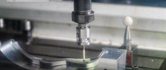
Vertical drilling machine 2Р135Ф2 with a six-spindle turret head, with a cross table and numerical control (CNC) is designed for drilling, reaming, countersinking, reaming, threading and milling in small-scale and mass production of various industries.
2R135F2 drilling machine is used for processing body parts and parts such as “flange”, “cover”, “plate”, “lever”, “bracket”.
The electrical circuit and CNC make it possible to carry out the following technological operations on the machine:
- Drilling;
- End trimming (countering);
- Boring;
- Threading;
- Deep drilling;
- Milling.
Operating principle and design features of the machine
The presence on the machine of a six-spindle turret for automatic tool change, a cross table with program control allows for coordinate processing of parts such as covers, flanges, panels without preliminary marking and the use of jigs.
2R135F2 vertical drilling machine has large ranges of spindle speed and feed rates, which fully ensure the choice of standard cutting modes when processing various structural materials.
2R135F2 machines ensure the accuracy of the center distances of machined holes up to 0.10-0.15 mm and can operate in an automatic cycle (in this mode, multi-operational processing of parts with a large number of holes is performed).
Design of the machine 2Р135Ф2 . A column is mounted on the base of the machine, along the rectangular vertical guides of which the spindle head (support) carrying the turret moves. The gearbox and feed reducer are rigidly mounted on the column. The cross table has a base along which the slides carrying the table itself move in the transverse direction. The latter, in turn, can move in the longitudinal direction along the slide guides. The movement of the slide and table is carried out from the gearboxes.
Numerical control system . The machine model 2Р135Ф2 is equipped with a numerical control device “ Coordinate S70-3 ”, the machine model 2Р135Ф2-1 is equipped with a CNC device 2П32-3 , which ensure simultaneous movement of the table along the X and Y axes when positioning control of movement along the axis (from the coordinate), makes it possible to control by turning the turret, select the value of the working feed and spindle speed. The device has a digital display and allows for input of corrections for tool length.
The positional rectangular CNC system is closed; code converters are used as measuring devices. The positioning accuracy of the table and support is 0.05 mm, the discreteness of programming and digital display is 0.05 mm. Number of controlled coordinates: total - three; simultaneously - two.
The design organization is the Experimental Research Institute of Metal-Cutting Machine Tools (ENIMS) and the Sterlitamak Machine Tool Plant named after. V.I. Lenin.
2R135F2 machine was accepted for serial production in 1979.
The accuracy class of the machine is N according to GOST 8-77. The quality category is the highest.
§ 2. VERTICAL DRILLING MACHINE 2Р135Ф2-1 WITH CNC. Technical specifications.
Section: LIBRARY OF TECHNICAL LITERATURE Short path https://bibt.ru<<Previous page Book table of contents Next page>>
The 2R135F2-1 vertical drilling machine is designed for drilling, countersinking, reaming, threading, light straight milling of parts made of steel, cast iron and non-ferrous metals in small-scale and mass production. A turret head with automatic tool change and a cross table with program control allow coordinate processing of parts such as covers, flanges, panels, etc. without preliminary marking and the use of jigs. Machine accuracy class P.
Technical characteristics of the machine 2Р135Ф2-1. The largest diameter of the workpiece is 35 mm; the largest diameter of the cut thread is M24; maximum milling width 60 mm; number of tools 6; number of spindle rotation speeds (total/per program) 12/12; spindle speed limits 35.5-1600 min-1; number of feeds along the Z axis 18; limits of working feeds along the Z axis 10-500 mm/min; speed of rapid movement of the table and slide 7000 mm/min, and when milling 2200 mm/min; speed of rapid movement of the caliper 4000 mm/min; table working surface size 400x710 mm; overall dimensions of the machine 1800x2400x2700 mm.
The CNC device type 2P32-3 is designed to control the process of positioning and rectangular processing (parallel to the coordinate axes). The software carrier is an eight-track punched tape, a method for specifying movements in absolute coordinate values. There is a digital display and 15 corrections for tool length can be entered. The CNC system is closed; BS155A selsyn is used as feedback sensors. The positioning accuracy of the table and slide is 0.05 mm, the discreteness of specifying movements and digital display is 0.01 mm. The number of controlled coordinates of all/of them simultaneously is 3/2.
Basic mechanisms and movements of the 2R135F2-1 vertical drilling machine. On base A (Fig. 68) a column B is installed, along the vertical guides of which the caliper G with turret D moves (feed along the Z axis). A gearbox, which transmits the main movement to the spindle, and a caliper feed box G are attached to the column. Cross table B, consisting of a table and a slide, makes two mutually perpendicular feed movements along the X', Y' axes from the gearboxes E.
Rice. 68. Kinematic diagram of a vertical drilling machine 2Р135Ф2-1 with CNC
Skip to navigation
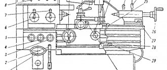
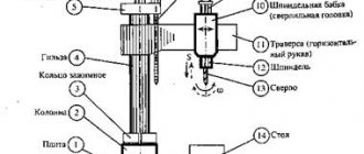
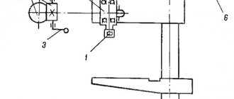
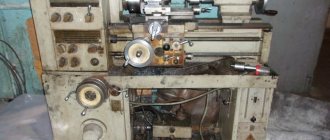
Location of the main parts of the drilling machine 2Р135Ф2
Location of the main components of the 2р135ф2 machine
Designation of the main parts of the drilling machine 2Р135Ф2
- Machine base
- Table slide
- Turret
- Spindle head (caliper)
- Gearbox
- Feed reducer
- Control pendant
- Cabinet with electrical control equipment
- Cabinet with CNC equipment
- Column
- Cross table
On the base (bed) 1 of the machine there are slides 2 of the cross table, which has telescopic protection for the guides. A spindle head moves along the vertical guides of the column, on which a six-spindle turret head is mounted, allowing automatic tool change according to a control program. To speed up manual tool replacement, a special pressing device is provided in the turret. The machine can be controlled from a pendant control panel.
Movements in the machine
- The main movement is the rotation of the spindle with the tool
- Movement along the machine axes:
- X-axis - longitudinal feed - longitudinal movement of the table along the slide guides
- Y axis - transverse feed - transverse movement of the slide along the bed guides
- Z axis - vertical feed - vertical movement of the spindle head (support) along the rack guides
To control table movements (X and Y coordinates) from a program recorded on punched tape, machines are equipped with various CNC devices (one of the most common is the CNC “Coordinate S-70”). Feed along the Z coordinate is carried out in cyclic control mode. For coordinate movements of the table, manual data input on the CNC console can also be used. The presence of a digital display allows you to visually monitor the position of the table, as well as monitor the correctness of the program recording on punched tape.
The machines provide feedback on the position of the working bodies on each of the two movements controlled by the punched tape. Circular electrical contact code converters are used as feedback sensors. Movements of the turret head during fast and working strokes in both directions are limited by adjustable cams acting on switches (electric stops).
Kinematic diagram of the drilling machine 2Р135Ф2-1
Kinematic diagram of the drilling machine 2р135ф2-1 with CNC 2П32-3
The kinematic diagram of the machine (Fig. 4.6) consists of the following independent kinematic chains: main movement drive (rotation of the turret spindles); cross table feed drive; caliper drive with turret head; turning the turret head; pressing tools out of spindles.
Main movement chain
Main movement chain: two-speed asynchronous electric motor M1 (N = 4/4.5 kW; n = 1470/990 rpm) - 29/41 gear transmission - shaft I - shaft II (through gears 24/48 and 36/36 at engaged couplings M1 and M2 or through gear 14/36 with engaged coupling M3) - shaft III (via gears 14/36 and 48/24 with engaged couplings M4 and M5) - shaft V through bevel gear 21/21 - to one of turret spindles through 35/42 gears; 31/49; 49/47; 47/35.
Cross table feed drive chain
The feed drive chain of the cross table has two gearboxes, one of which moves the table along the slide (X-axis), and the second drives the movement of the slide along the frame (Y-axis).
Kinematic chain of the slide drive
The kinematic chain of the slide drive ensures their fast, medium and slow movements. Fast movement (at a speed of 7000 mm/min): M4 electric motor (N=0.6 kW; p=1380 rpm) - 16/40 gears; 34/22; 22/52; 52/34 - ball screw.
Moving at medium speed (200 mm/min): M4 electric motor - 16/64 gears; 25/55; 25/55; 38/42; 22/52; 52/34 - ball screw. Slow movement (at a speed of 50 mm/min): M4 electric motor - 16/64 gears; 25/55; 25/55; 16/64; 22/52; 52/34 - ball screw. A feedback sensor is mounted on the ball screw.
The table moves along the slide from the M5 electric motor (N = 0.6 kW; n = 1380 rpm); the kinematic chain of the drive of this movement is similar to the kinematic chain of the drive of the slide movement.
Turret Caliper Drive Chain
Caliper drive chain with turret head: DC electric motor M2 (N = l.3 kW; n = 50..2600 rpm) - 13/86 gear (or 37/37 gear - 4/25 worm gear - lead screw, equipped with a brake clutch (preventing arbitrary lowering of the caliper when the electric motor is turned off) and a remote control feedback sensor.
Turret rotation drive chain
Turret head rotation drive chain: M3 electric motor (N=0.7/0.9 kW; n= 1400..2700 rpm) - 23/57 gear - 1/28 worm gear - 16/58 gear - turret body .
Pressing tools out of spindles
Pressing tools out of spindles: M3 electric motor - 18/52 gear (with the clutch engaged) - 1/28 worm gear - 21/21 gear - eccentric mounted in the groove of the turret head rotation axis and pressing tool.
Lubricating the turret support
Lubrication of the turret head support is carried out forcibly according to the following scheme: MZ electric motor - 18/52 gears; 52/75 - EZ eccentric, driving the plunger pump.
Gearbox lubrication
The gearbox is lubricated by a gear pump driven by the gearbox electric motor through a V-belt. The oil supplied by the pump enters the distribution chamber, where it is distributed to lubricate all moving parts of the gearbox and electromagnetic clutches, and then drained into the reservoir. The oil level is controlled by an oil indicator.
Lubrication of caliper feed gearboxes and cross table
Lubrication of the caliper feed gearboxes and the cross table is carried out by spraying oil onto the gears. The oil level is monitored visually using oil indicators.
Lubricating the guides and screw pairs of the cross table
The guides and screw pairs of the cross table are lubricated manually using a lubricator. The bearings of the turret spindles are lubricated with grease.
Coolant supply
The coolant is supplied from a centrifugal pump. To cool the tool in the cutting zone, an individual drive is provided, which allows you to direct a stream of coolant to the desired location. The supply of coolant in the automatic cycle begins when the caliper moves down (the beginning of the working feed) and stops when the caliper begins to return to its original position (in this case, the corresponding toggle switch must be turned on on the control panel).
Electrical equipment of the machine
The electrical equipment of the machine consists of a separate cabinet of relay automation and CNC, as well as elements installed directly on the machine. Electrical connections between the machine components and the CNC are made by harnesses in metal hoses ending with connectors.
The electrical circuit of the machine provides the following operating modes:
- commissioning;
- semi-automatic with task input from CNC switches;
- semi-automatic with task input from punched tape;
- automatic with task input from punched tape.
The mode is selected using switches located on the control panels of the machine and the CNC.
Kinematics of a vertical drilling machine 2Р135Ф2-1. Rotate the turret head.
Section: LIBRARY OF TECHNICAL LITERATURE Short path https://bibt.ru<<Previous page Book table of contents Next page>>
Kinematics of the machine. The main movement of the 2Р135Ф2-1 machine, the turret spindle, receives from an asynchronous two-speed electric motor M1 (N = 4/4.5 kW, n = 1000/1500 min-1) through a gear z = 29-41, an automatic gearbox providing six rotation speeds by switching electromagnetic couplings M1-M5 and then through gears z = 21-21, z = 37-37, z = 37-42, z = 31-49-47-35 (wheel z = 35 is installed on each of the six spindles , but only the one located on the running spindle receives rotation).
Kinematic chain equation for minimum spindle speed
The gearbox is lubricated by a pump driven by the M1 electric motor through a V-belt drive. The hole in the spindle for installing the tool is made under Morse taper No. 4.
The vertical feed of the 2Р135Ф2-1 support with a turret head is carried out from a DC electric motor M2 (N = 2.2 kW, n = 3000 min-1). Lead screw XXXIII with a pitch Рх.в = 8 mm is connected by a cross coupling to the shaft of a non-contact synchronizer type BS-155A, which is a feedback sensor along the Z coordinate.
Working feeds of the caliper occur when the electromagnetic clutch M6 is turned on, through gears z=13-86, z=37-37-37, z=4-25. Rapid movement of the caliper is carried out when the M7 clutch is engaged through gears z=37-37, z=4-25. Rapid movement speed of the caliper
An electromagnetic clutch is installed on shaft XXXII, which brakes the working feed along the Z coordinate. On shaft XXXIV there is an impeller for spraying oil.
Rice. 68. Kinematic diagram of a vertical drilling machine 2Р135Ф2-1 with CNC
The rotation of the turret head of the vertical drilling machine 2Р135Ф2-1 is carried out from the M3 electric motor (N = 0.75 kW, n = 1500 min-1) through gears z = 52-17, z = 18-52 with the M8 coupling engaged, a worm pair z = 1-28, gear pair z = 16-58. The head is secured by spring-loaded caliper rods located in the grooves of the turret. When the M8 clutch is turned on, the worm z = 1 cannot turn the worm wheel z = 28, and therefore, while rotating, moves downward. By moving downwards through a rack and pinion pair with a rack wheel z = 27, shaft XX with eccentric E1 rotates. The turret head is released from E1 through a system of levers. At the same time, the second rack wheel z = 27 moves the rack on shaft XVI, thereby disengaging the wheel z = 47 on shaft X. The kinematic chain connecting the rotation drive to the spindle opens. The worm z=1 reaches a hard stop, and the turret begins to rotate to change the tool.
Simultaneously with the rotation of the turret head through gears z = 16-58, z = 30-30, a positional command device operates, which gives commands to select the position of the turret head, stop direct rotation and enable reverse rotation (the M9 clutch is turned on, M8 is turned off). The turret rotates in reverse until it reaches the hard stop of the caliper and stops. In this case, the worm z = 1, turning out of the worm wheel z = 28, moves upward; shaft XX rotates in the opposite direction, gear z = 47 is engaged with wheel z = 35. The head is fixed and the spindle receives working rotation.
Pressing out the tool of the 2R135F2-1 machine from the turret spindle is carried out from the M3 electric motor through wheels z = 18-52 with the M10 clutch engaged, a worm gear z = 1-28, a gear pair z = 21-21, and an E3 eccentric installed in the axis groove turning the turret head.
Lubrication of the 2Р135Ф2-1 turret caliper is carried out using an M3 electric motor through wheels z = 18-52-75, shaft XV, on which an eccentric E2 is installed, driving the plunger pump.
Positioning is accomplished by moving the table and slide. Gearboxes for longitudinal and transverse movements are identical in design and provide fast, medium and slow movement of the table and slide. An electric drive with step control is used here (see Fig. 26), the approach to a given point occurs first quickly, and then slowly at a “creeping” speed. Milling is performed at medium speed. Let's consider the sled movement reducer. Rapid movement of the slide occurs when the M11 clutch is turned on, then the movement from the M4 electric motor (N = 1.1 kW, n = 1500 min-1) is transmitted through gear pairs z = 40-40, z = 34-26-22-52-34 onto the rolling screw nut XXXIX with a pitch of P = 5 mm. The speed of rapid movement is determined from the expression
Slow movement of the slide occurs when the M12 clutch is engaged. Then the movement from shaft XXXIII is transmitted to the lead screw through gears z = 16-64, z = 25-55, z = 25-55, z = 16-64, z = 22-52-34. The average movement of the table is carried out from the M4 electric motor through gears z = 16-64, z = 25-55, z = 25-55, z = 38-42 (with the M13 clutch engaged), z = 22-52-34. Then
An electromagnetic brake is located on the lead screw XXXIX. Through an M14 cam clutch, the lead screw is connected to a feedback sensor - a synchronizer.
The thread-cutting chuck of the vertical drilling machine 2R135F2-1 allows you to cut threads from M6 to M24. When cutting threads, it is necessary that the machine feed per spindle revolution be slightly less than the pitch of the thread being cut. For example, when cutting M12x1.75 threads in cast iron workpieces, we select the cutting speed v = 4.7 m/min, then the spindle rotation speed n = 125 min-1, and the tap feed Smin = = nPn.r = 125 * 1.75 = 220 mm/min. The nearest smaller feed on the machine is Smin = 200 mm/min. The feed difference between the tap and the machine spindle is compensated by the chuck.
Skip to navigation
Setting up the machine
Regardless of the position of the operating mode switch on the CNC console, the adjustment mode is turned on by switch 23 located on the machine control panel (Fig. 4.7). In the adjustment mode, carried out by means of controls located on the machine console, the following is performed: turning the turret to a given position; pressing out the tool; turning spindle rotation on and off; moving the table along the X and Y axes in accordance with the selected speed and direction; moving the turret support along the Z axis in accordance with the task.
Machine control panel 2р135ф2-1
Setting the working parts of the machine to the zero position
The working parts of the machine are set to the zero position automatically before the “Program Entry” command. When button 15 is pressed, the turret support quickly rises until the limit switch is activated along the Z coordinate. The table moves until the limit switches are activated along the X and Y coordinates, and at the same time commands are sent to the CNC about the initial position of the working parts. The installation cycle is complete.
Rotating the turret
To select the position of the turret head, switch 24 is set to the desired position. By pressing button 6, the cycle of turning the turret head to the position specified by switch 24 begins. When you press button 6 and there is no task, the head moves non-stop.
Turning on the spindle in the “Setup” mode
The spindle is turned on in the “Adjustment” mode for all operations (except for thread cutting) with button 21, and turned off with button 22 (when threading, buttons 21 and 22 do not work). The spindle rotation speed is set by switch 27.
Movement of working bodies along the X, Y, Z axes
Movement of working bodies along the X, Y, Z axes. The selection of the working axis is made by switch 4.
The selection of fast, medium or slow movement is made by switch 7, and the selection of the direction of movement is made by switch 5.
Setting the program start in the XY plane
To adjust the start of the program in the XY plane, catchers or center finders are used. In manual mode, the spindle axis is aligned with the beginning of the program, and the zero offset values along the X and Y axes are entered on the CNC control panel, which give zero readings on the digital display.
The machine is adjusted along the Z axis after installing the cutting tool in the turret spindle. In the initial position of the caliper, check that the turret head does not touch the device with the workpiece clamped in it when rotating.
Technical characteristics of the machine 2Р135Ф2
| Parameter name | 2Р135Ф2 |
| Basic machine parameters | |
| The largest drilling diameter in steel is 45, mm | 35 |
| The largest diameter of cut threads in steel is 45, mm | M24 |
| The smallest and largest distance from the end of the spindle to the table surface, mm | 40..600 |
| Distance from the axis of the vertical spindle to the rack guides (overhang), mm | 450 |
| Largest cutter diameter, mm | 100 |
| Maximum milling depth, mm | 2 |
| Maximum milling width, mm | 60 |
| Longitudinal movement of the table along the slide guides (X-Axis), mm | 630 |
| Transverse movement of the slide along the bed guides according to the program (Y-Axis), mm | 360 |
| Maximum movement of the spindle head according to the program (Z axis), mm | 560 |
| Caliper. Spindle head. Spindle | |
| Spindle speed, rpm | 45..2000 31..1400 |
| Number of spindle speeds | 12 |
| Speed of rapid movement of the support (spindle head), m/min | 4 |
| Number of caliper feeds along the Z axis, mm | 18 |
| Caliper feed, mm | 10..500 |
| Maximum permissible torque, Nm | 200 |
| Spindle taper | |
| Desktop | |
| Dimensions of the working surface of the table, mm | 400 x 710 |
| Maximum load on the table (center), kg | |
| Number of T-slots Dimensions of T-slots | 3 |
| Speed of rapid movement of the table and slide, m/min | 7 |
| Feed speed of table and slide during milling, m/min | 0,22 |
| Minimum table movement speed, m/min | 0,05 |
| Positioning accuracy of the table and slide along the stroke length, mm | 0,05 |
| CNC system 2P32-3 | |
| Number of controlled coordinates | 3 |
| Number of simultaneously controlled coordinates | 2 |
| Discreteness of setting the movement of the table, slide and support, mm | 0,01 |
| Electrical equipment, drive | |
| Main motion drive electric motor, kW | 3,7 |
| Electric motor for driving the spindle head (support), kW | 1,3 |
| Electric motor for moving the slide and table, kW | 1,1 |
| Electric motor for driving the turret head, kW | 0,75 |
| Electric coolant pump X14-22M, kW | 0,125 |
| Machine dimensions | |
| Machine dimensions, mm | 1800 x 2170 x 2700 |
| Machine weight, kg | 5390 |
- Vertical drilling machine with numerical control 2Р135Ф2-1. Operating manual 2Р135Ф2-1.00.000 РЭ, 1983
- Grachev L.N. Design and adjustment of computer-controlled machines and robotic complexes, 1986, p. 122
- Panov F.S. Working on CNC machines, 1984, p.163
- Barun V.A. Working on drilling machines, 1963
- Vinnikov I.Z., Frenkel M.I. Driller, 1971
- Vinnikov I.Z. Drilling machines and work on them, 1988
- Loskutov V.V Drilling and boring machines, 1981
- Panov F.S. Working on CNC machines, 1984
- Popov V.M., Gladilina I.I. Driller, 1958
- Sysoev V.I. Handbook for a Young Driller, 1962
- Tepinkichiev V.K. Metal cutting machines, 1973
Bibliography
Related Links. Additional Information
- Classification and main characteristics of drilling-milling-boring group of machines
- Selecting the right metalworking machine
- Machine repair technology
- Methodology for checking and testing drilling machines for accuracy and rigidity
- Directory of drilling machines
- Manufacturers of drilling machines in Russia
- Generations of CNC systems. Terms and concepts of CNC systems
- Russian manufacturers of modern CNC systems
- Review of Russian-made CNC systems
- Recommendations for choosing CNC devices
- Problems with modernized CNC machines: tips and tricks from professionals
- Requirements for ensuring stability and safety of machine control systems
Home About the company News Articles Price list Contacts Reference information Interesting video KPO woodworking machines Manufacturers
Vertical drilling machine with turret head 2Р135Ф2-1
Specifications
| Parameter | Meaning | |
| Model | ZK5140 | ZK5150 |
| Maximum feed force, kN | 16 | 16 |
| Maximum torque, Nm | 350 | 350 |
| Morse spindle taper type | № 4 | № 5 |
| Servomotor power, kW | 3 | 4 |
| Rotation speed range, min -1 | 31,5 … 1400 | 31,5 …1400 |
| Fast feed speed, mm/min | 4000 | 4000 |
| Feed range, mm/min | 10 … 2000 | 10 … 2000 |
| Spindle body stroke, mm | 600 | 600 |
| Work table travel along the X axis, mm | 1000 | 1000 |
| Worktable travel along the Y axis, mm | 600 | 600 |
| Spindle stroke along the Z axis, mm | 250 | 250 |
| Work table size, mm | 1000x630 | 1000x630 |
| Maximum distance between spindle and work table, mm | 650 | 650 |
| Positioning accuracy along the axes, mm along the X, Y axes along the Z axis | ±0,02 ±0,03 | ±0,02 ±0,03 |
| Position repeatability on all axes, mm | 0,01 | 0,01 |
| Machine dimensions, m | 2.8x2.4x2.9 | 2.8x2.4x2.9 |
| Weight, kg | 6500 | 6500 |
GDC series CNC drilling machines
| This series of machines belongs to the portal type machines, the two racks of which are connected by a fixed crossbar. The three axes are equipped with precision ball screws, ensuring smooth movement and high precision. The spindle assembly has high rigidity and precision. |
Specifications
| Parameter | Meaning | |
| Model | GDC1012 | GDC1216 |
| Work table dimensions, mm | 1000x1250 | 1250x1600 |
| Distance between posts, mm | 1570 | 1820 |
| Maximum load on the table, k N | 15 | 16 |
| Dimensions of groove T (holes), mm | M16 | 22 |
| Maximum movement along the X-axis, mm without tool magazine with tool magazine | 1250 1150 | 1600 1700 |
| Maximum movement along the Y axis, mm | 1000 | 1250 |
| Headstock movement (Z axis), mm | 400 | 400 |
| Distance between the spindle cone and the table surface, mm maximum minimum | 500 100 | 500 100 |
| Spindle taper (7:24) | VT40 | VT40 |
| Spindle speed, min -1 | 40 … 2500 | 40 … 2500 |
| Maximum torque, Nm | 100 | 140 |
| Maximum axial cutting force, N | 8000 | 10000 |
| Maximum drilling diameter, mm | 32 | 32 |
| Maximum thread diameter. thread, mm | M20 | M20 |
| Working feed, mm/min | 1 … 5000 | 1 … 4000 |
| Rapid movement along the X, Y axes, m/min | 15 | 10 |
| Rapid movement along the Z axis, m/min | 10 | 10 |
| Maximum tool length, mm | 300 | 300 |
| Number of tools | 10 | 10 |
| Positioning accuracy, mm along the X-axis, along the Y-axis along the Z-axis | 0,032 0,032 0,022 | 0,042 0,032 0,022 |
| Repeatability, mm X-axis, Y-axis Z-axis | 0,018 0,018 0,012 | 0,020 0,018 0,012 |
| CNC system | Siemens 802D | Siemens 802D |
| Main engine power, kW | 7,5 | 11 |
4. CNC milling machines
CNC milling machines are designed for processing flat and spatial surfaces of workpieces of complex shapes. The designs of CNC milling machines are similar to those of traditional milling machines, the difference from the latter lies in the automation of movements along the NC during shaping.
The classification of CNC milling machines is based on the following features:
• spindle location (horizontal vertical);
• number of coordinate movements of the table or milling head;
• number of tools used (single-tool and multi-tool);
• method of installing tools into the machine spindle (manually or automatically).
Based on their layout, CNC milling machines are divided into four groups:
• vertical milling machines with a cross table (652OF3, MA655F3, etc.);
• cantilever-milling (6R13F3, 6R13RF3, etc.);
• longitudinal milling (6M610F3-1, etc.);
• widely versatile instrumental.
In vertical milling machines with a cross table (Figure , a), the table moves in the longitudinal (X axis) and transverse (Y axis) horizontal directions, and the milling head moves in the vertical direction (Z axis).
Rice. 3. Layout of CNC milling machines with the designation of the coordinate axes X, Y, Z and W (a – vertical milling machine with a cross table; b – cantilever milling machine; c – longitudinal milling machine; d – longitudinal milling machine with fixed cross member; d – widely-universal milling machine)
In cantilever milling machines (Fig. 3, b), the table moves along three coordinate axes (X, Y and Z), and the headstock is stationary. In longitudinal milling machines with a movable crossbar (Fig. CNC.4, c), the table moves along the X axis, the spindle head moves along the Y axis, and the crossbar moves along the Z axis. In longitudinal milling machines with a fixed crossbar (Fig. 3, d) the table moves along the X axis, and the spindle head moves along the Y and Z axes.
In widely universal tool milling machines (Fig. 3, e), the table moves along the X and Y axes, and the spindle head moves along the Z axis.
Vertical milling machine 400V
The machine model 400V is designed for complex processing of parts made of various materials in small-scale and mass production. The machines perform drilling, linear, contour and volumetric milling, boring, threading, etc. operations.
Technical specifications
| Parameter | Meaning |
| Dimensions of the working surface of the table, mm | 900 x 400 |
| Largest programmable movements: | |
| - longitudinal movement (X), mm | 560 |
| -lateral movement (Y), mm | 400 |
| - vertical movement (Z), mm | 460 |
| Speed of rapid movement along the axes: | |
| X, Y, m/min | 30 |
| Z, m/min | 25 |
| Positioning accuracy along the X, Y, Z axes, mm | ± 0.005 |
| Spindle end taper with 7:24 taper | 40 |
| Spindle speed limits, min -1 | 80…8000 |
| Maximum torque on the spindle, Nm with a motor from 4 to 7.5 kW | 35…60 |
| Main drive power, kW | 4…7,5 |
| Tool change time (from tool to tool), sec | 2.5 |
| Overall dimensions, m | 2.33x2.62x2.64 |
| Machine weight, kg | 4500 |
CNC milling and boring machine 450 V
The machine model 450V is designed for complex processing of parts made of various materials in small-scale and mass production. The machine performs drilling, contour and volumetric milling, boring, threading, etc. It has two stationary tables, which are mounted on a fixed welded frame and 3 coordinates:
-X-axis—longitudinal movement of the slide along the bed guides;
- Y axis - transverse movement of the upper column along the slide guides; - Z axis - vertical movement of the spindle head along the column guides.
Movement along all three axes is carried out using ball screws. The machine is equipped with a cutting zone enclosure with sliding doors on linear rolling guides and a chip conveyor.
Technical specifications
| Parameter | Meaning |
| Dimensions of the working surface of the table, mm | 2150 x 500 |
| Largest programmable movements: | |
| - longitudinal movement (X), mm | 2×1000;2000 |
| -lateral movement (Y), mm | 400 |
| - vertical movement (Z), mm | 460 |
| Rapid movement speed on all axes, m/min | 25…30 |
| Range of working feeds by coordinates, mm/min | 1 …15000 |
| Positioning accuracy along the X, Y, Z axes, mm | ± 0,010 |
| Spindle end taper with 7:24 taper | 40 |
| Spindle speed limits, min -1 | 80..8000 |
| Maximum torque, Nm | 35…60 |
| Tool magazine capacity, pcs. | 24 |
| Tool change time, sec. | 12 |
| Main drive power, kW | 4…7,5 |
| Number of tools, pcs. | 20, 40 and more |
| Overall dimensions, mm | 4010x3460x3110 |
| Machine weight, kg | 9500 |
CNC milling and boring machines 600V, 800 V
The machines are designed for complex processing of parts made of various materials in small-scale and mass production. The machine performs drilling, straight-line, contour and volumetric milling, boring, threading, etc. operations.
Technical specifications
| Parameter | Meaning | |
| Model | 600V | 800V |
| Table surface dimensions, mm | 1250 x 600 | 1600(1250)x800 |
| Guide groove width, mm | 18N7 | 18N7 |
| The largest programmable movements: - longitudinal movement (X), mm - transverse movement (Y), mm - vertical movement (Z), mm | 1000 600 800 | 1400 (1000) 1000 800 |
| Range of working feeds, mm/min | 1 …12000 | 1 … 12000 |
| Rapid movement speed on all axes, m/min | 12…15 | 12…15 |
| Positioning accuracy along the X, Y, Z axes, mm | ±0.010 | ±0.010 |
| Spindle end taper with 7:24 taper | 40 | 40 |
| Spindle speed limits, min-1 | 80…8000 | 80…8000 |
| Maximum torque, Nm with engine from 10 to 18 kW | 60- 140 | 60… 140 |
| Main drive power, kW | (10-18,5) | 10…18,5 |
| Tool change time (from tool to tool), sec | 7 (2.5) | 12 |
| Number of tools, pcs | 20, 40 and more | 20, 40 and more |
| Overall dimensions, mm | 2800x2700x3210 | 3730x3460x3690 |
| Machine weight, kg | 8400 | 9200 |
| CNC system | SINUMERIC 802D | SINUMERIC 802D |
Vertical milling machines GF2171, GF4471, 6T13F3
The machines are designed for multi-operation processing of parts of complex configurations made of steel, cast iron, non-ferrous and light metals, as well as other materials. Along with milling operations, the machines can perform precision drilling, boring, countersinking and reaming of holes.
The large drive power of the main movement, a wide range of feeds and spindle speeds, and high rigidity of the machine design allow the use of cutters made of high-speed steel, as well as tools equipped with plates made of hard and superhard synthetic materials.
The machines are equipped with a three-coordinate CNC device and servo
adjustable electric feed drives, which allows processing of complex curved surfaces.
⇐ Previous7Next ⇒
Recommended pages: